 Djen Timo Kühnel
 Tim Helps
 Jonathan Rossiter2,3
- 1EPSRC Centre for Doctoral Training in Robotics and Autonomous Systems (FARSCOPE), University of Bristol and University of the West of England, Bristol, UK
- 2Bristol Robotics Laboratory, Bristol, UK
- 3Department of Engineering Mathematics, University of Bristol, Bristol, UK
Bouncing locomotion is used frequently in the animal kingdom for high-speed movement over land. Animals also change their stiffness and shape to improve their locomotion ability. Both bouncing movement and stiffness- and shape-changing capabilities have been recently explored in robotics. In this article, a novel soft locomotion robot, VibroBot, is presented, capable of moving using a bouncing gait by inducing whole-body oscillations through rotation of an internal out-of-balance mass. VibroBot is capable of changing both its stiffness and its shape to tackle challenging terrain and to overcome obstacles. When the robot is stiff, it is capable of high-frequency oscillatory locomotion suited to movement on hard surfaces. While in a compliant state, it uses a lower-frequency higher-amplitude hopping gait suitable for traveling over soft or loose ground. Forward speeds of 8.5 cm/s (0.34 body lengths/second) on hard floor in VibroBot’s stiff state and 5 cm/s (0.2 body lengths/second) on sand in its compliant state were recorded. VibroBot can also selectively change its shape to climb obstacles with heights up to 3 cm (20% of the robot’s height in its stiff state), far greater than its hopping apex height (1 cm). Both simple bouncing gaits and stiffness- and shape-changing abilities show great promise for improving the locomotion abilities of soft robots.
Introduction
Animals move over the land using a wide variety of gaits, including walking, hopping, running, and a large number of high-speed quadrupedal gaits, such as trot, canter, and gallop. Such gaits allow animals to move across a vast range of terrains, while wheeled systems can only access around 50% of the earth’s landmass (Raibert, 1986a). While the wide selection of high-speed gaits appears to vary considerably, they are broadly mechanically very similar. They may be categorized as bouncing gaits, as demonstrated by the ability of the spring-mass or “SLIP” model (Blickhan, 1989; McMahon and Cheng, 1990) to predict their center of mass dynamics remarkably well. The simplest bouncing gait is the hop, whereby a system alternates between a ballistic flight (flight phase) and elastic rebound in contact with the ground (stance phase). More complex gaits may have each leg experience stance phase at a different time during the gait cycle.
Seminal research building robotic hopping systems began in the 1980s at the MIT Leg Laboratory (Raibert, 1986a,b), where one-legged hopping systems that could move in two (Raibert and Brown, 1984) and three (Raibert et al., 1984) dimensions were constructed. While capable of locomotion, the machines were expensive, complicated, and power-hungry. More recently, hopping robots have been constructed that achieve hopping locomotion simply, cheaply, and economically through free vibration of a curved beam (Reis and Iida, 2011, 2014). In these robots, a rotating out-of-balance mass excites a resonant oscillation in the hopping system, causing the robot to hop and travel through the environment due to asymmetries in ground friction (Reis et al., 2013).
Animals also adapt their morphology to alter their locomotion abilities. Many legged animals, including humans, adjust their leg stiffness to control running and hopping in various circumstances: to choose a gait with a smoother ride at the cost of increased energy expenditure (McMahon, 1985; McMahon et al., 1987), to control hopping frequency when hopping (Farley et al., 1991) and stride frequency when running (Farley and Gonzalez, 1996), or to maintain similar center of mass dynamics when running on surfaces of varying stiffness (Ferris et al., 1998). Humans achieve this leg stiffness control by adjusting their ankle stiffness and limb geometry when hopping (Farley et al., 1998; Farley and Morgenroth, 1999), and by adjusting their knee stiffness during running (Arampatzis et al., 1999).
Researchers have also constructed robots that change their shape and stiffness. The Hylos robot was a four-wheeled robot that adapted its posture to tackle irregular terrain and maintain stability (Grand et al., 2004). Building upon this, the PAW robot was a quadrupedal hybrid wheeled-leg robot, with actuated wheels at the end of springy legs (Smith et al., 2006a,b). In its rolling mode, PAW rolled using its wheels and could adjust individual leg angles to perform inclined turning and stable braking. While in its legged mode, PAW could lock its wheels and move using a bounding gait. Matching the stiffness-changing behavior of humans, research using the EduBot platform demonstrated that structure-controlled leg stiffness variation could be used to improve locomotion speed and efficiency (Galloway et al., 2011, 2013). Most recently, origami has been incorporated into wheeled robots, producing a system whose wheels passively change diameter to maximize traction when moving against varying loads (Felton et al., 2014) and a robot capable of actively varying its wheel diameter to overcome various obstacles, using large wheels with spokes to climb steps and hurdles and small wheels to crawl through small gaps (Lee et al., 2014).
Evidently, stiffness- and shape-changing abilities provide considerable advantages for locomotion systems; however, such abilities have yet to be combined with the simple, cheap, and economical locomotion mechanism involving rotation of an out-of-balance mass, described above, in a locomotion robot. In this research, such a robot, VibroBot, is presented. VibroBot is an affordable soft robot capable of simple hopping locomotion achieved by exciting whole-body oscillations through rotation of an internal out-of-balance mass. In addition, VibroBot is able to drastically change its shape and stiffness to tackle challenging obstacles and environments.
Recently, the term Morphological Computation (Pfeifer and Bongard, 2006) has become popular in the field of Soft Robotics to describe systems in which control complexity is reduced by taking advantage of passive dynamics in the structure of the system, for example in the work of Felton et al., mentioned previously, whereby passive wheels adapt their diameter to improve locomotion without requiring input from a controller. VibroBot may be considered to use morphological computation to its advantage in the sense that a complex hopping gait is achieved using only one control variable (rotor angular velocity) due to the passive dynamics inherent in the robot.
VibroBot was designed to compete in the RoboSoft Grand Challenge Terrestrial Race. RoboSoft is a coordination action for the field of Soft Robotics with the aim of encouraging collaboration and scientific progress in the field. The RoboSoft Grand Challenge was the first outdoor competition for soft robots and comprised two distinct challenges: a manipulation task and a terrestrial race. VibroBot was designed to compete in the terrestrial race only. For the full competition guidelines, see http://www.robosoftca.eu/.
This article describes the final design of VibroBot and analyzes the robot’s locomotion mechanism based on its performance in the RoboSoft Grand Challenge Terrestrial Race, along with experiments comparing its kinematics on hard floor and loose sand while in different shape states. A review of VibroBot’s shape-changing abilities shows how they may be used to alter locomotion and to overcome obstacles. Finally, a comparison with similar robots is given to put VibroBot’s capabilities into perspective and limitations of the current design are discussed, including a number of possible future improvements. All video and numerical data recorded during experiments supporting this article is available at http://dx.doi.org/10.5523/bris.86hfdqz2t2pn1qyqunvbxr5gc.
Robot Design
The fundamental concept behind VibroBot is a soft, inflatable body propelled by a spinning, out-of-balance mass in its core. The robot consists of an elongated central section encased in a hard shell containing all of the moving parts. Inflatable bladders are mounted on the lower part of the shell to form a soft outer body with shape-changing capabilities. The robot and all important features can be seen in Figure 1.
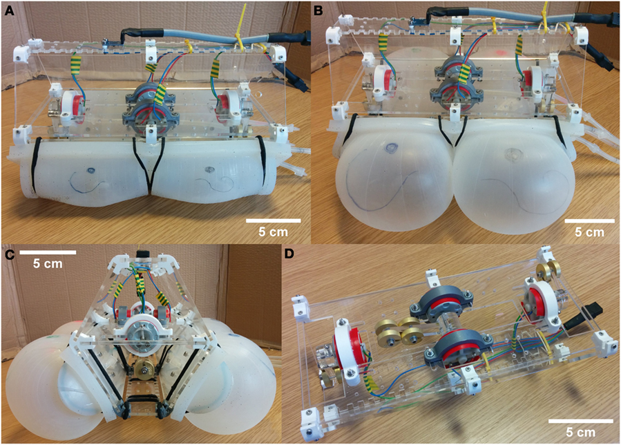
Figure 1. VibroBot. (A) Deflated state, side view; (B) inflated state, side view; (C) inflated state, front view; and (D) view of the core with half the shell and the bladders removed to show the three rotors: a longer central rotor with four weights and two peripheral rotors with two weights, respectively. Each weight has a mass of 10 g. The robot is 25 cm long. The cross section measures 16 × 15 cm when deflated and up to 35 × 22 cm when fully inflated.
Since VibroBot was created to compete in the RoboSoft Grand Challenge Terrestrial Race, its design was heavily influenced by the competition guidelines and challenge scenarios. According to the competition rules, robots were allowed to be tethered and teleoperated. During the challenge, points were awarded for shape-changing capabilities, measured by the ability to travel through a square opening whose width and height was lower than the standard dimensions of the robot (as defined prior to the challenge). Robots were also required to move across sand, climb a set of two steps each 5-cm tall and navigate tightly spaced obstacles without touching them.
Given the above requirements, VibroBot was designed to be teleoperated with no on-board logic and limited sensing capabilities in order to focus on the locomotion mechanics. The elongated body shape minimizes the robot’s cross section (width and height) in the deflated state and maximizes the impact of shape-changing through inflation of the bladders.
In the final design, three spinning out-of-balance masses are used: a large rotor of mass 40 g in the center for forward propulsion and two smaller peripheral rotors each of mass 20 g on either end (front and rear) of the body for steering. This configuration maximizes maneuverability as it allows turning on the spot as well as sideways motion. All three rotors are directly driven by DC motors (RF-500TB, Mabuchi Motor, Japan) and the applied torque is regulated using pulse-width modulation. The heavier central rotor is powered by two identical motors to increase torque and balance the weight of the robot.
For effective locomotion, the spinning masses need to generate a large reaction force relative to the overall mass of the robot. The main component of this reaction force is the centripetal force Fc, which is given by the equation
and is dependent on the rotating mass mR, angular velocity ω, and rotation radius (rotor length) r. The configuration of the rotors was therefore chosen to maximize mr and r in order to generate maximum force.
The rotors are mounted on a horizontal plate and encased within a hard shell of acrylic glass to avoid injury or damage from contact with the spinning masses. The custom-designed inflatable bladders are cast from silicone rubber (Dragon Skin® 10, Smooth-On, Inc., USA) and attached to the plates of the shell with bolts connecting to plates embedded in the silicone during casting. The inflatable bladders are in contact with the ground and act as the “feet” of the robot. Each bladder consists of two separate inflatable chambers, allowing for asymmetric inflation in the fore–aft direction. Thus, with two inflatable bladders each comprising two separate chambers, the robot can be tilted about both the sagittal axis and transverse axis. The robot is able to support a second pair of bladders on the upper plates of the shell, giving it a completely soft outer body and maximizing its ability to grow in size. However, it was found that the added weight compromised the robot’s locomotion capabilities and only the two lower bladders were used for the competition.
An umbilical cable attached to the robot provides electrical power to the motors and compressed air to the inflatable chambers. Each chamber in each bladder is attached by silicone tube to a network of valves, terminating at a single pump (D2028, Proto-PIC, UK). Operation of the valves allows any number of chambers to be closed off, connected to the pump or vented, allowing for holding, inflation, and deflation.
When maximally inflated, the bladders undergo a more than threefold increase in size, from a cross-sectional diameter of 4 cm to 13 cm. After inflation, the robot’s cross section is increased from 16 × 15 cm (fully deflated) to 35 × 22 cm. The length of the robot (25 cm) is not affected by inflation of the bladders. The total weight of the robot is 1.5 kg (excluding the umbilical cable).
To analyze the robot’s locomotion dynamics, an accelerometer (ADXL335, Analog Devices, USA) is mounted on its shell to capture acceleration data.
Locomotion
To propel VibroBot forward, whole-body oscillation is induced by the rotation of internal out-of-balance masses. Three separate rotors are used for navigation: a large rotor in the center of the robot that rotates about the transverse axis for forward and backward motion, and two smaller peripheral rotors on each end of the robot body, which rotate about the sagittal axis allowing for turning and sideways motion.
Stick-Slip Model
The robot’s ability to move is well described by a stick-slip locomotion model that has previously been used to describe and simulate other hopping and vibrating robots (Rubenstein et al., 2012; Reis et al., 2013; Reis and Iida, 2014). The mechanics by which rotation of an out-of-balance mass may be transformed into locomotion is described below. More detail can be found in the cited works.
Consider a robot consisting of a rotating out-of-balance mass and a chassis (Figure 2A). As the mass rotates, the robot experiences a reaction force that opposes the centripetal and inertial forces of the rotating mass. This reaction force may be modeled as a rotating rotor reaction force Fr with the same angular velocity as the rotating mass (Figure 2B).
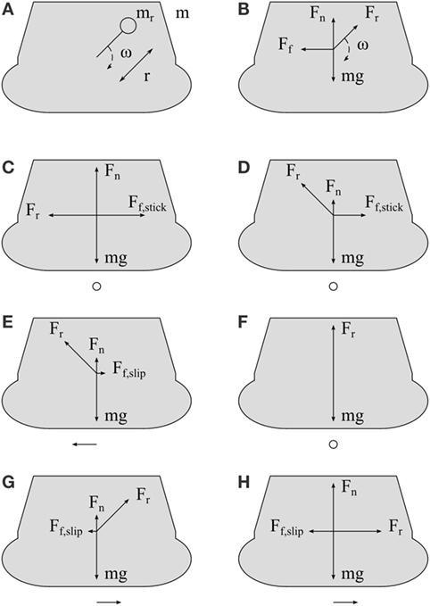
Figure 2. Simplified model and forces acting on VibroBot. (A) shows a simplified model of the robot (body cross section shown in gray), with a body of mass m and rotor mass mr at a distance r from its center of rotation, rotating at an angular velocity ω. (B) shows the forces acting on the robot: rotor reaction force Fr rotating at angular velocity ω, weight mg, normal reaction force Fn, and frictional force Ff. (C–H) show forces acting on the robot at various points in time during rotor’s rotation cycle, with the length of the vectors representing the magnitude of the force. A single vector beneath the robot in each image shows the net force on the robot. (C) shows VibroBot when rotor reaction force is negative and horizontal, with the rotor reaction force completely opposed by static frictional force Ff,stick. In (D), the positive vertical component of rotor reaction force has increased, reducing normal reaction force such that static friction force has reduced to the point that it is just equal to the horizontal component of rotor reaction force. (E) shows the robot having begun to move, moments later. As such, the lower kinetic frictional force Ff,slip now opposes the VibroBot’s movement. In (F), rotor reaction force is entirely vertical, such that normal reaction force has been reduced to 0 and no frictional force is felt. As the robot continues to move, the lower kinetic frictional force continues to resist its movement, and it continues to experience a net positive force (G) even when rotor reaction force is only positive and horizontal (H).
If the robot were in free space under no external forces, rotation of an out-of-balance mass would produce a rotational oscillation in the robot, with both mass and robot oscillating about their shared center of mass.
When the robot is resting on the ground under gravity, however, this motion is altered due to frictional forces. Frictional forces may be modeled as one of two forces resisting motion defined by
and
where Ff,stick is static frictional force, μstick is the static coefficient of friction, Fn is the normal reaction force between the two surfaces, Ff,slip is kinetic frictional force and μslip is the kinetic coefficient of friction. When the robot is not moving with respect to the ground, Ff,stick is used, and when the robot is moving, Ff,slip is used.
Figures 2C–H show the forces acting upon the robot at various points in time during the rotor’s rotation cycle, with the length of the vectors representing the magnitude of the force. The net force on the robot is shown beneath each subfigure. When the robot experiences a downward rotor reaction force, static frictional force prevents the robot from moving, since normal reaction force, and thus frictional force, is increased. When rotor reaction force is negative and horizontal, static frictional forces are still sufficiently large to oppose rotor reaction force (Figure 2C). As the vertical component of rotor reaction force begins to increase, normal reaction force and, thus, static frictional force is reduced, until the point at which static frictional force is just matched by the horizontal component of rotor reaction force (Figure 2D). Beyond this point, the horizontal component of rotor reaction force is greater than frictional force, and the robot begins to move. Since the robot is now moving, kinetic frictional force resists the robot’s movement, with the kinetic coefficient of friction being lower than the previous static coefficient of friction (Figure 2E). As the vertical component of rotor reaction force continues to increase, it may become large enough that normal reaction force is reduced to 0 (Figure 2F), and ballistic flight may occur. As long as the robot continues to experience a net positive horizontal force, it continues to move, and the lower kinetic frictional force continues to apply (Figures 2G,H). Thus, during the period in which the vertical component of rotor reaction force is positive, forces resisting forward movement are lower than forces resisting backward movement (compare Figure 2C and Figure 2H). Consequently, the symmetry of oscillation is broken and forward motion occurs over a gait cycle. In this manner, rotation of an out-of-balance mass produces forward movement and/or hopping in the robot.
Gaits
VibroBot’s locomotion dynamics are strongly influenced by the inflation of the four bladders the robot is resting on. Inflating or deflating the bladders has a direct impact on the stiffness of the “feet” both vertically (under compression) and horizontally (under shear), as well as the contact surface and friction on the ground. Besides the rotor masses, lengths, and angular velocity, these are the main parameters determining the stick-slip motion.
With the bladders inflated, the “feet” are relatively elastic and compliant, behaving like springs in the vertical direction. In this configuration, rotation of the out-of-balance mass produces a low-frequency, high-amplitude hopping gait with an apex height of around 1 cm, achieved when the rotor rotation frequency matches the resonant frequency of the body. With the bladders deflated, the robot’s “feet” become very stiff in the vertical direction and the resonant frequency is too high to be matched by the rotation of the mass so no effective up and down motion is generated. Instead, the rotation of the mass induces a forward and backward slipping motion. In this case, the resonant frequency is dependent on the friction on the ground and the elasticity of the “feet” in shear. Because of the high stiffness of the deflated “feet,” resonance occurs at a higher frequency than in the inflated state. The vertical force generated by the rotation of the out-of-balance mass, although not large enough to lift the robot off the ground, is sufficient to influence the friction and break the symmetry between forward and backward slipping. The result is a very effective slipping gait on flat ground.
VibroBot’s locomotion was tested on two different terrains: hard, flat, dry linoleum floor and loose, dry building sand (leveled but not compacted). Figures 3A,B show image sequences of the robot hopping on sand in its inflated state and slipping on hard floor in its deflated state, respectively. In Figures 3C,D, horizontal and vertical position data from both trials is plotted against time over a 3–s period to showcase the differences between the two gaits. Position data were obtained by manually tracking a single feature on the robot’s body in two 15 Hz video sequences using image processing software (ImageJ, NIH, USA).
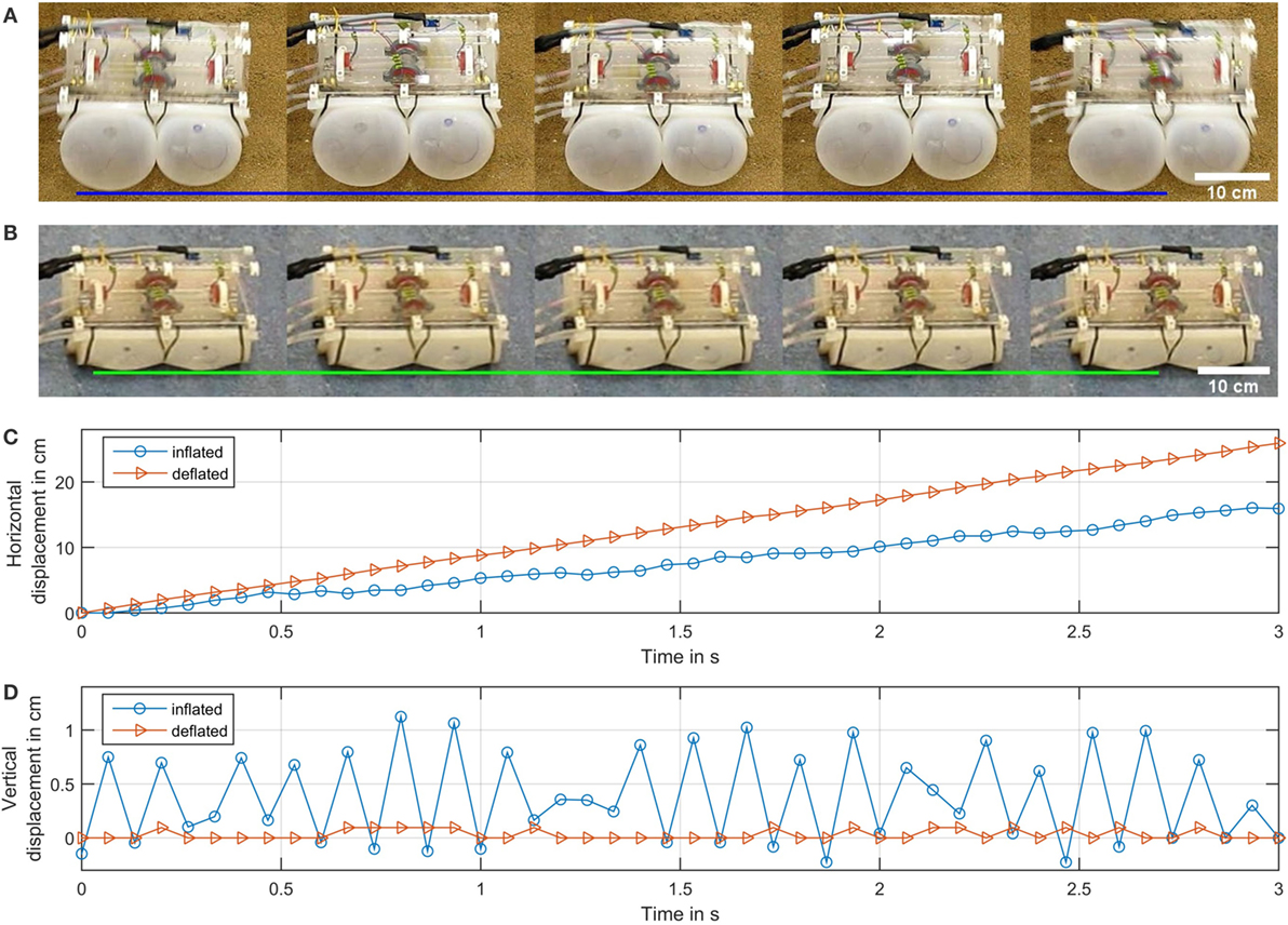
Figure 3. Comparison of locomotion in different inflation states and on different terrain. (A,B) show image sequences of the robot in motion in its inflated state on sand and in its deflated state on hard floor, respectively. Horizontal lines have been added to highlight vertical displacement. Graphs (C,D) show the robot’s horizontal and vertical displacement over a 3-s period. In VibroBot’s inflated state, rotation of the out-of-balance mass results in a low-frequency, high-amplitude hopping gait with a vertical displacement around 1 cm (typical hopping height). When the bladders are deflated, the robot adopts a high-frequency slipping gait with almost no discernible vertical displacement. Slipping on flat ground produces faster locomotion (8.5 cm/s) than hopping on sand (5 cm/s). Variations in speed and hopping height in inflated state are mainly due to uneven terrain.
The different gaits are useful to overcome challenging terrain with varying properties. The high-frequency slipping locomotion was found to be very effective for movement across hard floors, and VibroBot was able to achieve a forward speed of 8.5 cm/s or 0.34 body lengths/second (see Figure 3C) using this method on flat linoleum flooring. However, when placed on soft or loose ground, such as sand, high-frequency oscillations can be attenuated or absorbed entirely. Using the slipping gait on sand also results in a lot of sand being pushed in front of the robot and, in some cases, the robot will simply shake itself into a deeper and deeper hole, similar to the Saharan Sand Viper (Cerastes) burrowing into the sand (Young and Morain, 2003). This may be advantageous in some circumstances, for example in temporary robot anchoring during planetary exploration.
To move on soft or loose ground, low-frequency hopping locomotion is more effective. This locomotion was found to be slower than the high-frequency slipping locomotion on hard ground; however, on soft or loose ground where high-frequency oscillations do not produce effective forward movement, the low-frequency, high-amplitude hops allow progress to be made, resulting in a movement speed of 5 cm/s or 0.2 body lengths/second (see Figure 3C).
The movement speeds given above (8.5 and 5 cm/s on hard floor and sand, respectively) are the maximum speeds measured during testing but do not necessarily represent maximum achievable speeds in the respective configurations. In the deflated state, where the robot is in constant contact with the ground, friction is the biggest limitation on forward speed, although some amount of friction is crucial to break symmetry and allow for forward motion. For maximum forward speed, the ground friction should be adjusted to find an optimal tradeoff. This parameter was not systematically optimized during VibroBot’s design and, therefore, measured performance is likely suboptimal. During the bouncing gait in inflated state, ground friction is less important as the robot periodically loses ground contact and travels forward during its flight phase. In this configuration, other parameters, such as the inclination of the robot, which can help to direct hopping, have a larger impact. Again, this parameter was not systematically optimized prior to testing. The rotor angular velocity that maximizes forward speed is dictated by the robot’s resonant frequency, and was determined by observation.
Interestingly, when transitioning from a hopping to a slipping gait (by deflating the bladders), the rotation direction required to produce forward movement reverses. When the robot is in its inflated state, the rotor moves forward (in the same direction as the body) at its highest point, matching the locomotion mechanics described in the previous section. When the robot is deflated, however, the rotor must be spun backwards (moving backwards at its highest point) to produce forward motion. This phenomenon has been previously described and analyzed in further detail by Reis et al. (2013).
Resonant Frequencies
Figure 4 shows Fourier transforms of vertical acceleration data from an accelerometer mounted on the robot during locomotion on the two assessed terrains (hard floor and sand) and in two different states (inflated and deflated). The graphs show distinct peaks at the resonant frequencies. The double and triple peaks in Figure 4C are caused by a transition in resonant frequency from 14.09 Hz at the beginning to 13.44 Hz at the end of the recorded data. This is attributed to a change in tension in the umbilical cable as it is dragged along the floor. In deflated state on hard floor, the robot traveled the longest distance and, thus, the largest change in umbilical tension occurred. In the other experiments, distance traveled in the same amount of time was shorter and no such effect was observed.
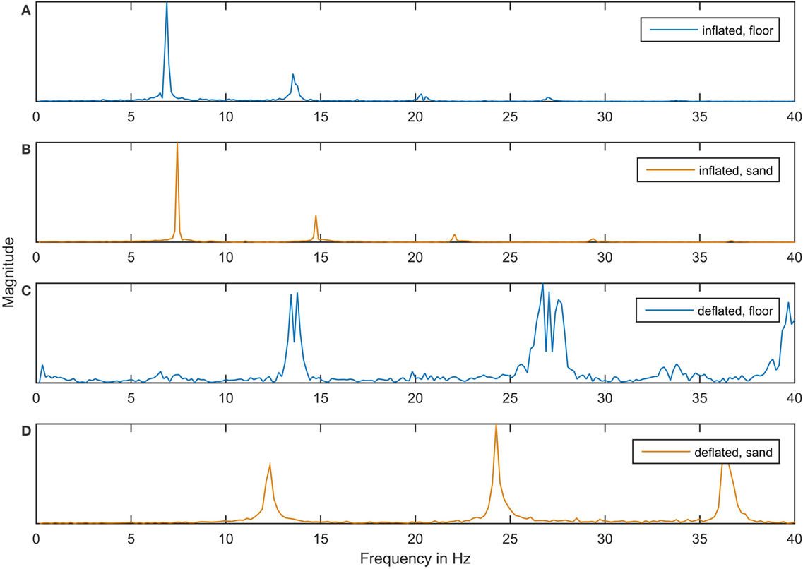
Figure 4. Resonant frequencies during hopping and slipping locomotion on different terrain. The graphs show Fourier transforms of vertical acceleration data recorded while VibroBot was hopping on linoleum floor (A), hopping on sand (B), slipping on linoleum floor (C) and slipping on sand (D). The Fourier transform shows the magnitude of the robot’s oscillation over the frequency range. The magnitude is dimensionless and normalized to the maximum value in each graph. Peaks in the magnitude show resonant frequencies, with the lowest-frequency peak corresponding to the respective rotation frequency of the rotor. The blurred peaks in (C) are caused by changes in umbilical cable tension as it was dragged along behind the robot, leading to a slight shift in resonant frequency over the duration of the experiment.
The peaks at the lowest frequency in each graph indicate the rotation frequency of the rotor. There is a clear distinction between the two inflation states, indicative of the different resulting gaits: during slipping locomotion on the floor with the bladders deflated (Figure 4C), resonance occurs at 13.6 Hz (on average), whereas during hopping locomotion on the floor with the bladders inflated (Figure 4A), resonance occurs at 6.9 Hz.
These peaks reveal an interesting effect of the sand on VibroBot’s locomotion. Figures 4C,D show that in the deflated state, resonant frequencies are slightly lower on sand than on hard floor, which can be attributed to a damping effect of the sand. However, in the inflated state (Figures 4A,B) there is a slight increase in resonant frequency on sand when compared to hard ground. We hypothesize that this due to another effect counteracting the dampening: if the sand slightly deforms around the bladder, it might be providing a higher contact area and, thus, better support than the flat ground, where the contact area with the round, inflated bladders is very small. The sand thereby increases the effective stiffness of the bladders, leading to a slight increase in resonant frequency.
Figure 4 also shows that a large amount of energy is being dissipated in higher frequency harmonic oscillations when the robot is in the deflated state (Figures 4C,D). Further study is needed to determine the effects of these harmonics on locomotion and body motion.
During experiments, only two inflation states were used, however, it would be possible to use various inflation pressures to achieve various whole-body natural frequencies and, thus, produce more than the two gaits demonstrated in this robot.
Steering
In the above analysis, only forward motion using the central rotor was investigated. Figure 5 showcases VibroBot’s steering capability and maneuverability using the peripheral rotors in its deflated state, showing it navigating obstacles (vertical poles) during the RoboSoft Grand Challenge Terrestrial Race. The robot is shown at three different stages of the challenge and the blue lines indicate the path that the robot traveled. Central and peripheral rotors were used alternatively, so discernable regions of straight forward motion (using the central rotor) and steering and transverse movement (using the peripherals rotors) can be seen in the robot’s path. During practice sessions, central and peripheral rotors were successfully used simultaneously to travel in a curve (moving forwards while turning), or to travel diagonally (forward and transverse movement). In inflated state, use of the peripheral rotors proved much less effective. Due to the lower mass and shorter arms of the rotors, generated forces are too small for the robot to bounce and lose ground contact, and slipping is not effective in the inflated state because of the larger contact area and increased ground friction. In the inflated state, leaning the robot to one side using asymmetrical inflation of the bladders proved a more effective mechanism for steering. Use of the peripheral rotors was especially problematic in a few cases where the two rotors on either end of the robot did not match rotation frequency with the resonant frequency of the robot or one another. Since the rotors are not feedback-controlled, this occurrence results in chaotic motion that does not produce effective steering.
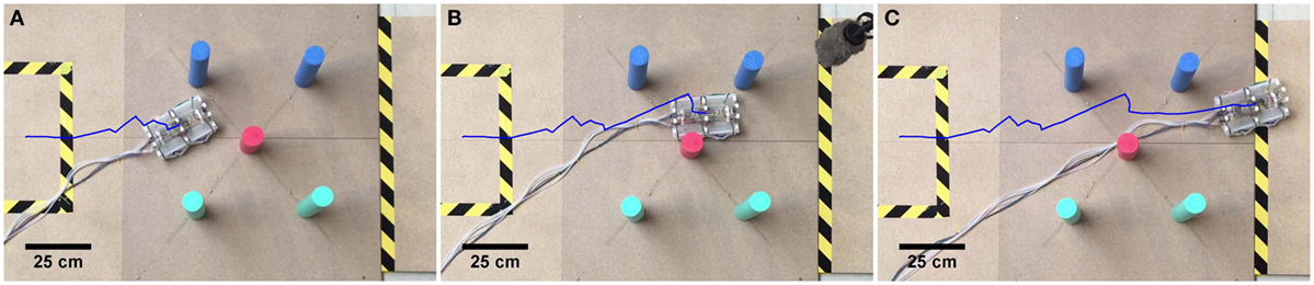
Figure 5. VibroBot in its deflated state, navigating obstacles during the RoboSoft Grand Challenge. The blue line shows the path that the robot traveled at the beginning (A), half-way through (B) and at the end of the challenge (C). The path reveals sections of straight forward travel using the large rotor, and sections of steering and transverse movement using the peripheral rotors. In the last section (C), it can be seen from the traveled path that the robot veers to the left side during forward motion, due to the umbilical cable pulling the back of the robot to the right.
Adaptive Morphology
The robot’s morphology is an important parameter for its locomotion. Hopping amplitude, frequency, friction, and balance are all influenced by the inflation of the four bladders. This means that the inflation needs to be controlled in order to produce desired behaviors, however, the adaptable morphology can itself be used as a powerful control mechanism.
During forward locomotion, leaning the body forward by partially deflating the front bladders will cause the robot to perform longer and more directed hops, allowing it to move faster and deviate less from a straight path. Similarly, leaning the body slightly to one side by deflating the bladders on that side will cause the robot to tend to move toward that side. This can be used as a steering mechanism that does not require additional motors. In fact, in the inflated state, this was found to be a more powerful steering mechanism than the peripheral rotors. Unevenly inflated bladders on either side cause the robot to veer to one side and even spinning the peripheral rotors in the opposite direction cannot correct for this in some cases. Similarly, leaning the robot forward by inflating only the back bladders can cause the robot to move forward regardless of the rotation direction of the central rotor.
VibroBot’s shape-changing ability can also be used to overcome obstacles greater than the hopping apex height of the robot (1 cm). Inflation of the bladders can be used to lift the body up to 7 cm off the floor. The body can be held stably in this elevated position by only three inflated bladders. This allows the robot to move its body partly onto the obstacle where it can then rest, deflating and inflating the other bladders successively while gradually moving its entire body onto the obstacle. Figure 6 shows VibroBot successfully climbing a step of 1.8 cm – almost twice the robot’s hopping apex height – using a sequence of shape changes. In practice sessions, VibroBot succeeded in fully climbing steps of up to 3 cm height. During this climbing maneuver, some bladders in contact with the ground or step are deflated, partially inflated, or fully inflated. As such, when the motors were engaged, the excited locomotion was a hybrid locomotion, some way between the hopping and slipping gait.
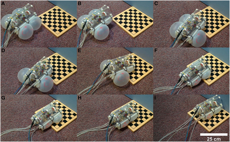
Figure 6. VibroBot climbing a step of 1.8 cm height. (A) Approaching the step fully inflated. (B) Deflating front-right bladder. (C) Moving front-right corner above obstacle. (D) Deflating front-left bladder until the front edge rests on the obstacle. (E) Moving forward until the back bladders touch the edge of the obstacle. (F) Deflating back bladders and slightly inflating front bladders to maximize traction on the obstacle. (G) Shuffling forward until the body is more than half-way onto the obstacle. (H) Deflating front bladders to rest the body flat on the obstacle. (I) Shuffling forward until the entire body is on the obstacle.
During the RoboSoft competition, VibroBot unfortunately failed to climb the first of two 5-cm steps it was challenged to overcome. The weight and tension of the umbilical caused the robot to slip back off after having lifted the front half of its body onto the step.
Conclusions and Outlook
We have presented and demonstrated VibroBot, a soft robot capable of controlled hopping and slipping locomotion induced by exciting whole-body oscillations through rotation of an out-of-balance mass. In addition, the robot’s capability to tackle challenging environments and difficult obstacles by changing its stiffness and shape was demonstrated.
By inflating or deflating VibroBot’s inflatable chambers, it is possible to alter its stiffness with respect to the ground, changing its locomotion dynamics to adopt different gaits. Specifically, a deflated, high-stiffness state was found to be suitable for locomotion on hard surfaces, and an inflated, low-stiffness state proved suitable for tackling soft or loose ground.
VibroBot’s maximum recorded forward speed was 8.5 cm/s (0.34 body lengths/second), not dissimilar to that of other robots which use the same locomotion mechanism. Two free vibration curved beam hoppers achieved horizontal velocities of 7 cm/s (Reis and Iida, 2011) and roughly 20 cm/s (Reis and Iida, 2014) respectively, the former traveling 0.15 characteristic lengths/second (characteristic length being the distance between top and bottom mass, since body length was not provided) and the latter traveling roughly 0.625 body lengths/second (body length estimated using image with scale).
VibroBot’s forward speed is dependent on internal factors, including the robot’s mass, resonant frequency, rotor rotation frequency, and force exerted by the rotor, as well as external factors, including ground friction. Its mass could be slightly reduced by removing structural material in areas where it is not required. Depending on the specific application, it might be advantageous to remove the peripheral rotors (sacrificing maneuverability in the deflated state) and instead rely on asymmetric inflation for steering. The robot’s natural frequency is a function of the inflation of its bladders; however, the robot’s highest recorded speed occurred with the bladders fully deflated. This speed might be improved by altering the bladder design. A previous study found that the optimal rotor rotation frequency for a similar robot was ~80% of robot resonant frequency, due to the presence of a ballistic flight phase, and increasing rotor rotation frequency above this frequency inhibited locomotion (Reis and Iida, 2014). The optimal rotor rotation speed for VibroBot was determined by observation as the speed at which the robot’s locomotion speed was greatest, and as such more detailed analysis might allow for maximization of the robot’s locomotion speed at various levels of bladder inflation. Increasing the force exerted by the rotor can be achieved by increasing the rotor radius or by increasing rotor mass. Increasing rotor mass has been shown to increase forward locomotion speed up to a point for similar robots, beyond which motion becomes chaotic (Reis and Iida, 2014). Conceivably, the motors could be incorporated in the rotor arms and powered by batteries that would double as spinning masses. This would dramatically increase the rotor-to-body weight ratio while also removing “dead” weights, although a wireless solution would be necessary to control motor speeds in this configuration. In a number of cases, the robot’s umbilical cable interfered with locomotion, so the power supply and air compressor could be moved on-board, making the robot entirely wireless; however, this would considerably increase the robot mass and likely inhibit locomotion overall.
The addition of a payload, although adding functionality to the robot, would certainly inhibit locomotion. The load would increase the robot mass and, thus, decrease locomotion speed, unless it were possible to add the payload attached to the rotors, increasing force exerted. If the payload were added to the robot body, the robot’s natural frequency would likely be reduced, considering the effect of an increase in mass on the dynamics of a spring–mass system.
The robot’s shape-changing ability can be used to overcome obstacles; by selectively inflating and deflating separate chambers in an appropriate order, it was possible for the robot to climb steps up to 3 cm high (20% of the robot’s height in deflated state), far greater than the robot’s hopping apex height (1 cm). We were unable to find descriptions of navigable obstacle heights for robots using the same locomotion mechanism. RHex, a robust compliant leg hexapedal locomotion robot whose height is 25 cm, can consistently navigate over simple 15 cm tall obstacles (60% body height) (Saranli et al., 2001).
Navigable obstacle height is limited by the size the inflatable bladders can reach before failure, which depends on the silicone rubber’s elongation at break. The silicone rubber used (Dragon Skin® 10, Smooth-On, Inc., USA) has a high elongation at break value of 1000% but failure tended to occur at the seams of the two-part mold before such high elongation was reached, reducing the safely achievable inflation. A single-part casting method, such as slush casting, would result in bladders lacking seams, but would increase casting complexity. Another limiting factor for navigable obstacle height is VibroBot’s hopping apex height, which could be increased by reducing the body mass to rotor reaction force ratio.
For mobile locomotion robots, it is often useful to consider how scaling the robot would affect its capabilities, to determine whether a larger or smaller version of the same robot would be more effective. As discussed previously, one factor influencing the locomotion abilities of robots using the same locomotion mechanism is the ratio of body mass to rotor reaction force (which mostly comprises centripetal reaction force). Assuming a constant average robot density, body mass is expected to scale with L3, while centripetal force depends upon rotor mass and the square of rotor radius and as such scales with L3·L2 = L5. Thus, the ratio of body mass to centripetal force scales with L3/L5 = L2, an interesting result implying a similar robot two times as large would be four times as effective at locomotion. However, changing the scale of the robot would also alter its resonant frequency, since the robot mass and bladder stiffness would be changed. The effect of bladder scale upon bladder stiffness at maximum inflation is not trivial to determine and beyond the scope of this article.
In future work, accelerometers and visual sensors could be used to implement a feedback control strategy to ensure the robot reaches a stable resonance, regardless of the terrain or inflation of the robot. VibroBot’s locomotion is the result of an oscillation at the robot’s natural frequency, and as such the speed of the motors does not need to be controlled precisely because they fall into resonance with the robot’s oscillation. However, when motor power is too low, the rotor will fail to achieve resonance and stall, and when motor power is too high, the rotors will fall into resonance with a different, higher frequency, producing no effective forward movement. In both cases, input power needs to be adjusted to revert to the desired resonance. On-board accelerometers and visual sensors could be used to detect when the incorrect oscillation frequency has been excited, and take appropriate action (during experiments it was found that the stable locomotion could be restored by returning motor power to 0 and slowly increasing it). Since the dynamics of the robot vary greatly with its inflation as well as the terrain, feedback is crucial to produce stable resonance under varying conditions. With the current robot, this was done by the human operator observing the robot and adjusting control inputs accordingly, but for the robot to become autonomous, a feedback controller using data from on-board sensors would need to be implemented. More extensive sensor data could also be used to further study the mechanics of the different gaits to improve efficiency.
By optimizing the body and bladder design and removing excessive material, VibroBot’s mass could be further reduced thereby allowing for a second pair of bladders on the top. This would not only make the robot exterior completely soft but could also enable rolling locomotion around the sagittal axis driven by sequential inflation and deflation of the bladders.
Stiffness- and shape-changing abilities are prominent in biological locomotion systems and provide clear advantages for locomotion. Such abilities should be explored more deeply and considered for implementation in current and future locomotion systems.
In its current form, VibroBot successfully competed against teams from around the world in the RoboSoft Grand Challenge, coming third overall in the Terrestrial Race.
Author Contributions
DK: design and construction of the robot, acquisition and evaluation of experimental data, and 50% written content. TH: design and construction of the robot, acquisition and evaluation of experimental data, and 50% written content. JR: development of fundamental concepts, project guidance, and review of written content.
Conflict of Interest Statement
The authors declare that the research was conducted in the absence of any commercial or financial relationships that could be construed as a potential conflict of interest.
Acknowledgments
We would like to thank all members of the Soft Robotics Group at the Bristol Robotics Laboratory for their invaluable ideas and suggestions that led to the final design of VibroBot. Finally, we would also like to thank the organizing team of the RoboSoft Grand Challenge for holding this exciting competition that gave the incentive for this project.
Funding
This work was partially funded by the FP7 RoboSoft Coordination Action on Soft Robots. JR is funded by EPSRC grants EP/M020460/1, EP/M026388/1 and EP/L015293/1. TH is funded by EPSRC grant EP/M026388/1. DK is funded by the EPSRC Centre for Doctoral Training in Future Autonomous and Robotic Systems (FARSCOPE) EP/L015293/1.
References
Arampatzis, A., Brüggemann, G.-P., and Metzler, V. (1999). The effect of speed on leg stiffness and joint kinetics in human running. J. Biomech. 32, 1349–1353. doi:10.1016/S0021-9290(99)00133-5
Blickhan, R. (1989). The spring-mass model for running and hopping. J. Biomech. 22, 1217–1227. doi:10.1016/0021-9290(89)90224-8
Farley, C. T., Blickhan, R., Saito, J., and Taylor, C. R. (1991). Hopping frequency in humans: a test of how springs set stride frequency in bouncing gaits. J. Appl. Physiol. 71, 2127–2132.
Farley, C. T., and Gonzalez, O. (1996). Leg stiffness and stride frequency in human running. J. Biomech. 29, 181–186. doi:10.1016/0021-9290(95)00029-1
Farley, C. T., Houdijk, H. H., Van Strien, C., and Louie, M. (1998). Mechanism of leg stiffness adjustment for hopping on surfaces of different stiffnesses. J. Appl. Physiol. 85, 1044–1055. doi:10.1016/0021-9290(89)90224-8
Farley, C. T., and Morgenroth, D. C. (1999). Leg stiffness primarily depends on ankle stiffness during human hopping. J. Biomech. 32, 267–273. doi:10.1016/S0021-9290(98)00170-5
Felton, S. M., Lee, D.-Y., Cho, K.-J., and Wood, R. J. (2014). “A passive, origami-inspired, continuously variable transmission,” in 2014 IEEE International Conference on Robotics and Automation (ICRA), 2913–2918.
Ferris, D. P., Louie, M., and Farley, C. T. (1998). Running in the real world: adjusting leg stiffness for different surfaces. Proc. Biol. Sci. 265, 989–994. doi:10.1098/rspb.1998.0388
Galloway, K. C., Clark, J. E., and Koditschek, D. E. (2013). Variable stiffness legs for robust, efficient, and stable dynamic running. J. Mech. Robot. 5, 11009. doi:10.1115/1.4007843
Galloway, K. C., Clark, J. E., Yim, M., and Koditschek, D. E. (2011). “Experimental investigations into the role of passive variable compliant legs for dynamic robotic locomotion,” in 2011 IEEE International Conference on Robotics and Automation (IEEE), 1243–1249.
Grand, C., Benamar, F., Plumet, F., and Bidaud, P. (2004). Stability and traction optimization of a reconfigurable wheel-legged robot. Int. J. Rob. Res. 23, 1041–1058. doi:10.1177/0278364904047616
Lee, D.-Y., Kim, J.-S., Park, J.-J., Kim, S.-R., and Cho, K.-J. (2014). “Fabrication of origami wheel using pattern embedded fabric and its application to a deformable mobile robot,” in 2014 IEEE International Conference on Robotics and Automation (ICRA), 2565.
McMahon, T. A. (1985). The role of compliance in mammalian running gaits. J. Exp. Biol. 115, 263–282.
McMahon, T. A., and Cheng, G. C. (1990). The mechanics of running: how does stiffness couple with speed? J. Biomech. 23, 65–78. doi:10.1016/0021-9290(90)90042-2
McMahon, T. A., Valiant, G., and Frederick, E. C. (1987). Groucho running. J. Appl. Physiol. 62, 2326–2337.
Pfeifer, R., and Bongard, J. (2006). How the Body Shapes the Way We Think: A New View of Intelligence. Cambridge, MA: MIT Press.
Raibert, M. H., and Brown, H. B. (1984). Experiments in balance with a 2D one-legged hopping machine. J. Dyn. Syst. Meas. Control 106, 75. doi:10.1115/1.3149668
Raibert, M. H., Brown, H. B., and Chepponis, M. (1984). Experiments in balance with a 3D one-legged hopping machine. Int. J. Rob. Res. 3, 75–92. doi:10.1177/027836498400300207
Reis, M., and Iida, F. (2011). “Hopping robot based on free vibration of an elastic curved beam,” in 2011 IEEE/ASME International Conference on Advanced Intelligent Mechatronics (AIM) (IEEE), 892–897.
Reis, M., and Iida, F. (2014). An energy-efficient hopping robot based on free vibration of a curved beam. IEEE/ASME Trans. Mechatronics 19, 300–311. doi:10.1109/TMECH.2012.2234759
Reis, M., Yu, X., Maheshwari, N., and Iida, F. (2013). Morphological computation of multi-gaited robot locomotion based on free vibration. Artif. Life 19, 97–114. doi:10.1162/artl_a_00084
Rubenstein, M., Ahler, C., and Nagpal, R. (2012). “Kilobot: a low cost scalable robot system for collective behaviors,” in Proc. – IEEE Int. Conf. Robot. Autom, 3293–3298.
Saranli, U., Buehler, M., and Koditschek, D. E. (2001). Rhex: a simple and highly mobile hexapod robot. Int. J. Rob. Res. 20, 616–631. doi:10.1177/02783640122067570
Smith, J. A., Sharf, I., and Trentini, M. (2006a). PAW: A Hybrid Wheeled-Leg Robot. ICRA, 4043–4048.
Smith, J., Sharf, I., and Trentini, M. (2006b). “Bounding gait in a hybrid wheeled-leg robot,” in 2006 IEEE/RSJ International Conference on Intelligent Robots and Systems (IEEE), 5750–5755.
Keywords: RoboSoft Grand Challenge, soft robotics, adaptive morphology, whole-body oscillation, terrestrial locomotion
Citation: Kühnel DT, Helps T and Rossiter J (2016) Kinematic Analysis of VibroBot: A Soft, Hopping Robot with Stiffness- and Shape-Changing Abilities. Front. Robot. AI 3:60. doi: 10.3389/frobt.2016.00060
Received: 01 August 2016; Accepted: 20 September 2016;
Published: 11 October 2016
Edited by:
Cecilia Laschi, Sant’Anna School of Advanced Studies, ItalyReviewed by:
Massimo Mastrangeli, Max Planck Institute for Intelligent Systems, GermanyRebecca Krone Kramer, Purdue University, USA
Copyright: © 2016 Kühnel, Helps and Rossiter. This is an open-access article distributed under the terms of the Creative Commons Attribution License (CC BY). The use, distribution or reproduction in other forums is permitted, provided the original author(s) or licensor are credited and that the original publication in this journal is cited, in accordance with accepted academic practice. No use, distribution or reproduction is permitted which does not comply with these terms.
*Correspondence: Tim Helps, dGltLmhlbHBzQGJyaXN0b2wuYWMudWs=