 Aaron Fishman1,2*
 Martin Stephen Garrad1,2,3
 Andrew Hinitt1,4Plinio Zanini1,2Tim Barker1
 Jonathan Rossiter1,2
- 1Department of Engineering Mathematics, University of Bristol, Bristol, UK
- 2Bristol Robotics Laboratory, Bristol, UK
- 3EPSRC Centre for Doctoral Training in Future Autonomous and Robotic Systems (FARSCOPE), University of Bristol and University of the West of England, Bristol, UK
- 4Department of Mechanical Engineering, University of Bristol, Bristol, UK
Soft limbs with anisotropic stiffness are common in nature and enable animals to solve a variety of tasks, including locomotion and manipulation. This mixture of hardness and softness enables animals to efficiently control the unpredictable contact forces that occur while performing such tasks. A challenge for soft robotics is to create artificial limbs that mimic natural mixtures of hardness and softness for use as a building block for soft, adaptable robots. This article presents the design of a novel pneumatic limb module with adjustable length and anisotropic stiffness. The artificial limb is designed with a rigid telescopic endoskeleton inside a rubber bellow, which we show is able to resist buckling, while remaining externally soft. Finally, we present the design of a hexapod walker based on the limb units.
1. Introduction
Soft robotics has recently emerged as a field, promising safer, more adaptable and more energy-efficient robots (Trivedi et al., 2008; Pfeifer et al., 2012; Trimmer, 2014). Soft robotics has taken particular inspiration from animals which display extreme softness, such as the jellyfish or octopus (Lin et al., 2011; Seok et al., 2013; Godaba et al., 2016). A significant advantage of such robots is that they can passively resist environmental perturbations, reducing the need for fast, complex control systems. However, most animals require a mix of softness and rigidity (see Figure 1 for examples); vertebrates have soft muscle around rigid skeletons, while Manduca sexta uses the rigid elements in its environment as a skeleton (Lin and Trimmer, 2010).
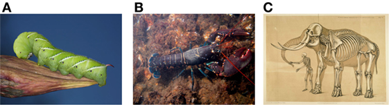
Figure 1. Examples of biological solutions to the problem of providing a soft structure with stiffness. (A) shows the Manduca sexta exploiting environmental features [Manduca Sexta by Daniel Schwen, from Wikipedia is under Creative Commons CC BY-SA 4.0], (B) shows a European Lobster with a rigid exoskeleton [European Lobster by Bart Brain, Public Domain], while in (C) both the human and elephant have rigid endoskeletons [A comparative view of the human and elephant frame by Benjamin Waterhouse Hawkins, Public Domain].
A challenge for soft robotics is developing systems which have the ability to be stiff when needed, while keeping the benefits of softness (Kim et al., 2013). Prior work in this area can be broadly divided into mechanisms that switch between stiff and compliant states such as the universal gripper (Brown et al., 2010), shape-memory polymer McKibben actuators (Takashima et al., 2010), or Stiff-Flop (Cianchetti et al., 2013) and those which combine stiff and rigid materials (Stokes et al., 2014). The integration of rigid mechanisms into compliant materials has been used to control the bending radius of an actuator (Galloway et al., 2013) to provide the coupling between length and volume in the McKibben actuator (Gaylord, 1958) and to determine the bending direction of pneumatic actuators (Ilievski et al., 2011). Commercially available pneumatic linear actuators are axially compliant but aim to minimize radial compliance entirely and thus sacrifice the associated benefits.
The integration of hard and soft is a particular challenge for the development of soft robotic limbs. Soft robotic limbs must maintain the inherent safety and robustness of soft robotics, while being capable of transmitting the forces necessary for interaction with the environment. The necessity of both compliance and force transmission means that buckling can be a significant problem for such structures. Thus, mechanisms that can prevent buckling without sacrificing the benefits of softness represent a significant contribution.
In this article, we introduce Hexo-Flexo bot, a hybrid hard–soft hexapod developed for the RoboSoft terrestrial locomotion challenge. The main contribution of Hexo-Flexo bot is a lightweight modular pneumatic limb, consisting of a telescopic endoskeleton inside a rubber bellow. The telescopic endoskeleton prevents buckling during locomotion by increasing both axial and radial stiffness, but maintains enough axial compliance to allow adaptation to small ground pertubations and pneumatic control of limb length.
This article will introduce the design and analysis of the pneumatic limb module, before describing the design of Hexo-Flexo bot and the lessons learnt from the RoboSoft Grand Challenge.
2. Design of Anisotropic Pneumatic Limb Module
The limb module comprises a soft rubber bellow with a rigid 3D-printed endoskeleton and end plugs to create an air tight seal. The Febi 8029 steering rack bellow was selected for its high stretch ratio of 3.4 (natural length 150 mm, compressed length 83 mm, and stretched length 280 mm). The bellow is sealed at either end with 3D-printed PLA plugs coated in yacht varnish to prevent leakage through the porous structure of the PLA. The endoskeleton consists of a series of concentric telescopic sections attached to the end plugs with a locking mechanism and epoxy resin, detailed in Figure 2. This structure prevents buckling, while allowing for controllable linear pneumatic actuation. Figure 3 shows the complete limb module with the endoskeleton.
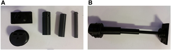
Figure 2. Assembly of a pneumatic limb. A set of 3D-printed PLA parts is shown in Panel (A). The interlocking cylindrical segments are placed inside of each other to form a telescope. The smaller plug is then fixed to the small telescope section using epoxy resin. The larger plug fixtures by rotating it into the locking groove on the larger end of the telescope and create the full assembly in Panel (B).
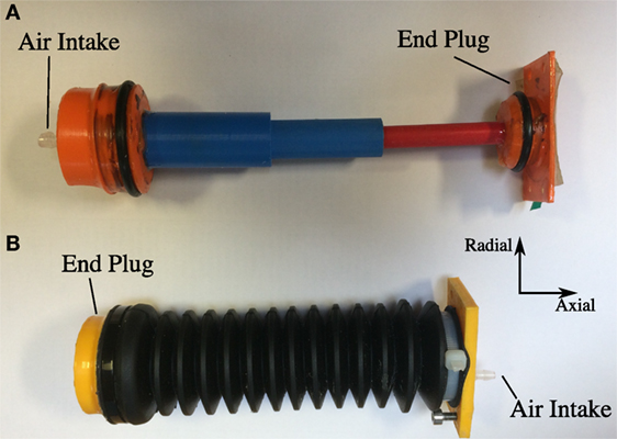
Figure 3. Rigid endoskeleton (A) and assembled pneumatic leg module containing endoskeleton (B).
There are several design parameters that may be explored, including the number and length of telescope stages and the gap size between stages (see Figure 4). The number of telescope stages determines the expansion ratio, which may be scaled to the maximum length of the bellow, if desired. The maximum number of telescope stages, Nmax, is given by
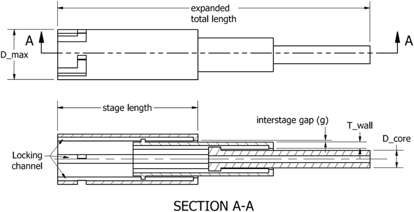
Figure 4. Design parameters of the limb module.
where Dmax is the maximum telescope diameter, Twall is the thickness of the wall, and Dcore is the diameter of the core telescope, and g is the spacing between stages. Increasing g increases the deflection at which the mechanism begins to stiffen radially (i.e., the looseness of the telescope). Thus, a desired radial stiffening point can be selected by appropriate choice of g. For example, a compliant surgical robot may require precise tip position and thus want to minimize radial deflection, while a snake robot may use greater compliance to adapt to obstacles in the environment.
The limbs for Hexo-Flexo bot were produced by a FDM 3D Printer (Makerbot, Replicator 2, USA). The 3D printing tolerances limited the number of stages to three. We designed for maximum radial stiffness and thus minimized the gaps.
Limb length was controlled by two vacuum pumps (D2028B, AIRPON, China) operated below their rated voltage (5 V instead of 12 V) to allow slower expansion and contraction and thus more control of limb length. Two solenoid valves (LHDA0523112H, Lee, UK) switch the module between the expanding, compressing, and holding states. Figure 5 shows the control architecture used to vary length.
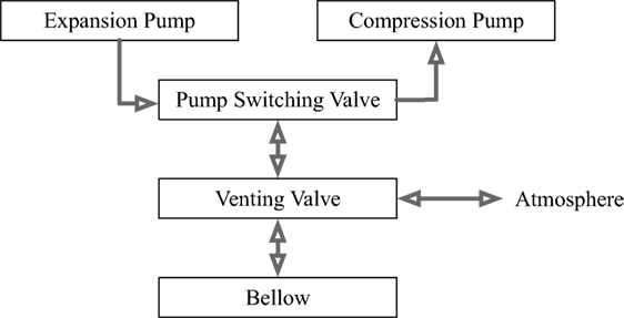
Figure 5. Length control architecture. Two vacuum pumps are used to provide the pressure changes. The first valve is used to switch which pump is connected to the bellow, while the second valve is used to set the resting pressure at a desired value.
3. Evaluation of Pneumatic Limb Module
In order to demonstrate the effectiveness of the anisotropic module, the performance of the limb was assessed both with and without the endoskeleton. All data collected are available at http://dx.doi.org/10.5523/bris.l9g38ayyb4nm15x3sotqrlf2p. The limb was mounted horizontally and the deflection of the tip from the horizontal plane due to gravity was compared in atmospheric (P = A), compressed (P < A), and pressurized states (P > A), where P is the pressure in the bellow and A is atmospheric pressure. Figure 6 shows that the endoskeleton provides significant rigidity in the radial direction, almost completely eliminating the deflection due to gravity.
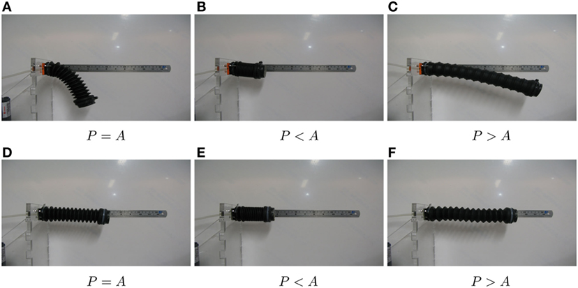
Figure 6. Comparison of the behavior of the pneumatic limb with and without the endoskeleton where P is the pressure in the bellow and A is atmospheric pressure. Panels (A–C) show the limb without the skeleton in the atmospheric, vacuum, and pressurized configurations. Panels (D–F) show the limb with the endoskeleton in the same configurations.
To quantify the impact of the addition of the telescopic structure, the stiffness of the system was measured in both the axial and radial directions at a variety of pressures. The module was mounted horizontally and the restoring forces were measured by a load cell (Vishay Tedea Huntleigh 1022, USA) as the module was compressed and released. Displacement was measured by a laser displacement meter (LK-G152, Keyence, Japan).
Figure 7 illustrates the telescopic module’s increased stiffness. Inclusion of the telescope increases radial stiffness in the compressed, atmospheric and expanded states by a factor of 13 (0.13–1.7 N mm−1; Figure 7A), 8 (0.03–0.24 N mm−1; Figure 7B), and 5 (0.02–0.17 N mm−1; Figure 7C), respectively, as summarized in Table 1. It is interesting to note that the stiffness of the telescopic system decreases as the limb module is expanded. We hypothesize that this is due to the increasing compliance of the telescope as it is extended.
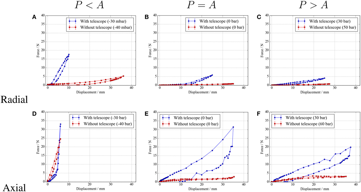
Figure 7. Effect of including the telescopic mechanism in the bellow under different pressures where P is the pressure in the bellow and A is atmospheric pressure. The top row shows the radial stiffness with and without the telescope in the compressed (A), atmospheric (B), and expanded states (C). The bottom row (D–F) shows the same information for axial stiffness.
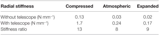
Table 1. Radial bellow stiffness with and without the telescopic mechanism.
The limb module’s increased stiffness is also observed in the axial direction. This is most significant in the atmospheric and expanded states, where the buckling of the bellow means there is very little stiffness without the telescope (Figures 7E,F and 8). By including the telescope, we increase stiffness by a factor 4.5 (4.0–18 N mm−1; Figure 7D), 11 (0.08–88 N mm−1; Figure 7E), and 6.5 (0.08–0.51 N mm−1; Figure 7F), as summarized in Table 2. Again, we note that the system is less stiff in the expanded state.
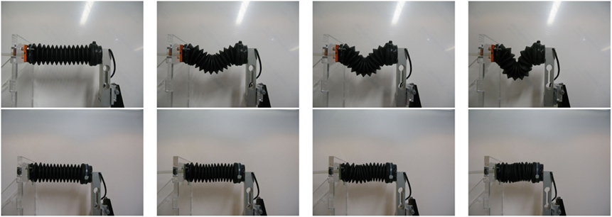
Figure 8. Response of the bellow to axial displacement. The top panels show the mechanism without the telescopic endoskeleton, while the bottom panels demonstrate the resistance to buckling provided by the endoskeleton.
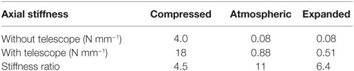
Table 2. Axial bellow stiffness with and without the telescopic mechanism.
We also note the unusual shape of the graph of axial stiffness in the compressed state with the telescopic mechanism (Figure 7). We believe that the two phases of this plot are explained by the stiction of the telescopic mechanism preventing full compression by the vacuum pump. In this case, further compression during testing compresses the bellow until the telescopic mechanism is at its minimum length. At this point, the abrupt increase in stiffness is due to the compressive stiffness of the telescope.
The inclusion of the telescopic mechanism increases both the axial and radial stiffness sufficiently to prevent buckling. Without the telescope, the limb buckles under the application of an axial force (see Figure 8). The increased stiffness provided by the telescopic mechanism prevents this buckling, allowing the limb modules to transmit the forces necessary for locomotion.
To demonstrate that the increased stiffness has not impacted the ability of the limb length to be controlled pneumatically, the displacement of the limb tip (with endoskeleton) was measured as the pressure was varied. Tip measurements were performed with a laser displacement meter (KG-152, Keyence, Japan), while the pressure was measured with a digital manometer (ExiaIICT4, Digitron, UK).
Figure 9 shows pressure against limb length. Initially, the limb length increases proportional to the pressure until the limb reaches maximum extension. When the pressure is released, there is a rapid drop in pressure, with relatively little change in length. The limb then relaxes back to its initial length. A similar behavior is observed for the compression test, with a longer relaxation time. These results show that it is possible to vary the limb length between the expanded and contracted states pneumatically.
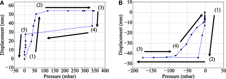
Figure 9. Pressure against limb extension for the actuation tests. The expansion test in (A) shows proportional extension during part (1), before reaching its maximum extension in part (2). During parts (3) and (4), the limb is vented and a rapid drop in pressure occurs. This is followed by a relaxation to resting length in part (5). The compression test in (B) shows similar behavior in parts (1) and (2) but exhibits a lag in relaxation in part (3) before returning to resting length in part (4).
To further illustrate this hysteresis and relaxation, two cycles of compression and expansion are shown in Figure 10. The compression test shows that the bellow responds to a drop in pressure with a reduction in length (0.72 strain, resting length 165 mm, and compressed length 120 mm). It takes approximately 40 s for the limb to reach its minimum length. When the vacuum is released, it relaxes back to its initial length. Ninety percent of the resting length is recovered within 30 s, followed by a slow relaxation of the remaining 10% over another 30-s period.
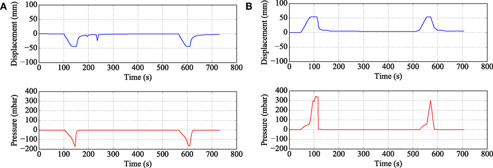
Figure 10. Displacement (top) and pressure (bottom) for two cycles of pumping. Panel (A) shows the compression test, while (B) shows the expansion test.
The expansion test displays qualitatively similar behavior. Compared to the compression test, the expansion phase takes longer to reach its maximum displacement (1.33 strain, extended length 220 mm), but recovers its initial length quicker. We suggest that this difference is due to the close proximity of the outer bellow sections causing an increase in stiction between the endoskeleton and bellows during compression.
The main drawbacks of the endoskeleton unit include added weight, reduced bandwidth, and reduced expansion ratio. The constructed endoskeleton unit adds 58 g, approximately doubling the weight of the module. The increase in inertia and introduction of friction between the telescopic stages will reduce the bandwidth of the unit. However, this can be compensated for by using a stronger pump. Finally, the expansion ratio of the module is reduced from 3.4 to 2.1. As discussed in Section 2, increasing the number of stages would allow for a smaller decrease in ratio, at the cost of weaker telescopic stages.
To summarize, we have shown that the inclusion of the telescopic endoskeleton provides sufficient stiffness in both the axial and radial directions to prevent buckling, but does not impact upon the ability to pneumatically control length by 30% in either direction. The slow response times of the unit limits the potential for use as an actuator, but is not a significant problem when the limb is used as a variable length or variable stiffness limb. Furthermore, actuation times can be reduced by running the pump at a higher voltage or by substituting a more powerful pump.
4. Design of Hexo-Flexo Bot
The proposed anisotropic limbs were used as the basis for an entry to the RoboSoft terrestrial locomotion challenge. This challenge called for a robot, which was capable of locomoting over a variety of terrains and being able to change size.
The design of Hexo-Flexo bot was motivated by two main principles. First, the scoring system of the grand challenge was heavily weighted toward the ability to expand or shrink. Thus, Hexo-Flexo bot was designed to have a significant change in size. Second, navigating terrain that was rough (sand), uneven (steps), and cluttered (obstacles) was a key aspect of the challenge. We believe that a walker with adaptable, compliant limbs would be capable of overcoming these tasks.
Figure 11 shows the system diagram of Hexo-Flexo bot. Hexo-Flexo bot is a six-legged walker with two anisotropic limb modules (as presented above) per leg, each controlled through separate valves. Hexo-Flexo bot is capable of supporting its own weight in natural, compressed, and expanded states (see Figure 12).
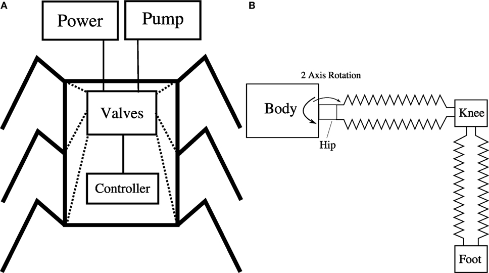
Figure 11. System diagram of Hexo-Flexo bot. The electromechanical system is shown in (A). A set of solenoid valves are controlled by an on-board microcontroller. Power and air pressure is supplied to the robot via an off–board tether. The leg module is illustrated in (B). Two of the above limb units are connected by a knee to allow size adjustments in two directions. The hip connects the leg module to the body and has two servos that allow the leg to move independently in the vertical and horizontal directions.
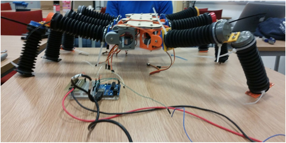
Figure 12. The completed Hexo-Flexo bot shown standing. All limb modules are in their rest state.
Each leg was actuated with two servo motors: a vertical servo motor (Hobbyking HK15328D) used to lift the leg from the ground and a rotational servo (TowerPro MG90S) used to swing each leg in the fore–aft axis. An on-board microcontroller (ATMEL ATMEGA328P) was used to control the servo motors and valves, with power and air pressure supplied via a tether. Figure 12 shows the complete Hexo-Flexo bot in preparation for the competition. Unfortunately, Hexo-Flexo bot was unable to compete due to technical difficulties with the main body of the robot, which fractured from stresses induced by the weight of the body.
5. Conclusion and Further Work
In this article, we have presented a novel modular pneumatic limb unit with anisotropic structural stiffness. The inclusion of an endoskeleton means the limb is able to resist buckling while maintaining the benefits of softness, including resistance to surface perturbations and adaptability. The limbs were pneumatically actuated to demonstrate their ability to controllably adjust to different terrains.
Future work will consider both improvements to the limb module and a simplified implementation of Hexo-Flexo bot to demonstrate the suitability of the limb module.
Improvements to the telescopic endoskeleton mechanism include investigating the use of alternative materials and manufacturing processes in order to reduce the friction that we believe causes the slow response times. The inclusion of a more powerful pumping system is also being considered. It is possible that with shorter response times and higher internal pressures, the limb module may also be used as a pneumatic actuator as well as a variable length limb.
Furthermore, the locking channel for the telescopic stage could be shaped to adjust the torsional stiffness of the system. A design in which the locking channel reduces in width along the telescope’s major axis would allow the torsional stiffness to be increased as the limb stretches.
The proposed anistropic limb modules are also suitable for incorporation into other soft, locomotive robots, such as one based on Whegs (Saranli et al., 2001) or hopping (Ahmadi and Buehler, 1999). The variable length of the limb module makes it a promising candidate for robots that must navigate through complex terrains, such as during search and rescue missions.
Author Contributions
All the authors performed conception and design, development, analysis and interpretation, manuscript writing, and final approval of manuscript.
Conflict of Interest Statement
The authors declare that the research was conducted in the absence of any commercial or financial relationships that could be construed as a potential conflict of interest.
Funding
This work was partially supported by the RoboSoft Coordination action in Soft Robotics and EPSRC Centre for Doctoral Training in Future Robotics and Autonomous Systems (FARSCOPE) EP/L015293/1. JR is supported by EPSRC grants EP/M026388/1 and EP/M020460/1. AF and TB are supported by Dyson Foundation Ph.D. scholarships. PZ was supported by the Science without Borders scheme from the National Council for Scientific and Technological Development (CNPq) of the Brazilian Government.
References
Ahmadi, M., and Buehler, M. (1999). “The ARL monopod ii running robot: control and energetics,” in Proceedings 1999 IEEE International Conference on Robotics and Automation, Vol. 3 (Detroit, MI: IEEE), 1689–1694.
Brown, E., Rodenberg, N., Amend, J., Mozeika, A., Steltz, E., Zakin, M. R., et al. (2010). Universal robotic gripper based on the jamming of granular material. Proc. Natl. Acad. Sci. U.S.A. 107, 18809–18814. doi: 10.1073/pnas.1003250107
Cianchetti, M., Ranzani, T., Gerboni, G., De Falco, I., Laschi, C., and Menciassi, A. (2013). “Stiff-flop surgical manipulator: mechanical design and experimental characterization of the single module,” in IEEE/RSJ International Conference on Intelligent Robots and Systems (Tokyo: IEEE), 3576–3581.
Galloway, K. C., Polygerinos, P., Walsh, C. J., and Wood, R. J. (2013). “Mechanically programmable bend radius for fiber-reinforced soft actuators,” in 2013 16th International Conference on Advanced Robotics (ICAR) (IEEE), 1–6.
Godaba, H., Li, J., Wang, Y., and Zhu, J. (2016). A soft jellyfish robot driven by a dielectric elastomer actuator. IEEE Robot. Autom. Lett. 1, 624–631. doi:10.1109/LRA.2016.2522498
Ilievski, F., Mazzeo, A. D., Shepherd, R. F., Chen, X., and Whitesides, G. M. (2011). Soft robotics for chemists. Angew. Chem. Int. Ed. 50, 1890–1895. doi:10.1002/anie.201006464
Kim, S., Laschi, C., and Trimmer, B. (2013). Soft robotics: a bioinspired evolution in robotics. Trends Biotechnol. 31, 287–294. doi:10.1016/j.tibtech.2013.03.002
Lin, H.-T., Leisk, G. G., and Trimmer, B. (2011). GoQBot: a caterpillar-inspired soft-bodied rolling robot. Bioinspir. Biomim. 6, 026007. doi:10.1088/1748-3182/6/2/026007
Lin, H.-T., and Trimmer, B. (2010). Caterpillars use the substrate as their external skeleton: a behavior confirmation. Commun. Integr. Biol. 3, 471–474. doi:10.4161/cib.3.5.12560
Pfeifer, R., Lungarella, M., and Iida, F. (2012). The challenges ahead for bio-inspired ‘soft’ robotics. Commun. ACM 55, 76–87. doi:10.1145/2366316.2366335
Saranli, U., Buehler, M., and Koditschek, D. E. (2001). Rhex: a simple and highly mobile hexapod robot. Int. J. Robot. Res. 20, 616–631. doi:10.1177/02783640122067570
Seok, S., Onal, C. D., Cho, K. J., Wood, R. J., Rus, D., and Kim, S. (2013). Meshworm: a peristaltic soft robot with antagonistic nickel titanium coil actuators. IEEE/ASME Trans. Mechatron. 18, 1485–1497. doi:10.1109/TMECH.2012.2204070
Stokes, A. A., Shepherd, R. F., Morin, S. A., Ilievski, F., and Whitesides, G. M. (2014). A hybrid combining hard and soft robots. Soft Robot. 1, 70–74. doi:10.1089/soro.2013.0002
Takashima, K., Rossiter, J., and Mukai, T. (2010). Mckibben artificial muscle using shape-memory polymer. Sens. Actuat. A Phys. 164, 116–124. doi:10.1016/j.sna.2010.09.010
Trimmer, B. (2014). A journal of soft robotics: why now? Soft Robot. 1, 1–4. doi:10.1089/soro.2013.0003
Keywords: soft robotics, variable length, pneumatic, robosoft, anisotropic-stiffness
Citation: Fishman A, Garrad MS, Hinitt A, Zanini P, Barker T and Rossiter J (2017) A Compliant Telescopic Limb with Anisotropic Stiffness. Front. Robot. AI 3:80. doi: 10.3389/frobt.2016.00080
Received: 01 August 2016; Accepted: 21 December 2016;
Published: 01 February 2017
Edited by:
Cecilia Laschi, Sant’Anna School of Advanced Studies, ItalyReviewed by:
Robert Shepherd, Cornell University, USACarmel Majidi, Carnegie Mellon University, USA
Tommaso Ranzani, Harvard John A. Paulson School of Engineering and Applied Sciences, USA
Copyright: © 2017 Fishman, Garrad, Hinitt, Zanini, Barker and Rossiter. This is an open-access article distributed under the terms of the Creative Commons Attribution License (CC BY). The use, distribution or reproduction in other forums is permitted, provided the original author(s) or licensor are credited and that the original publication in this journal is cited, in accordance with accepted academic practice. No use, distribution or reproduction is permitted which does not comply with these terms.
*Correspondence: Aaron Fishman, YWFyb24uZmlzaG1hbkBicmlzdG9sLmFjLnVr