 Filippo Arrichiello
 Alessandro Marino
 Francesco Pierri
- 1Department of Electrical and Information Engineering, University of Cassino and Southern Lazio, Cassino, Italy
- 2Department of Information and Electrical Engineering and Applied Mathematics, University of Salerno, Salerno, Italy
- 3School of Engineering, University of Basilicata, Potenza, Italy
The paper presents an architecture for distributed control of multi-robot systems with an integrated fault detection, isolation, and recovery strategy. The proposed solution is based on a distributed observer-controller schema where each robot, by communicating only with its direct neighbors, is able to estimate the overall state of the system; such an estimate is then used by the controllers of each robot to achieve global missions as, for example, centroid and formation tracking. The information exchanged among the observers is also used to compute residual vectors that allow each robot to detect failures on anyone of the teammates, even if not in direct communication. The proposed strategy considers both recoverable and unrecoverable actuator faults as well as it properly manages the possible activation of reactive local control behaviors of the robots (e.g., the activation of obstacle avoidance strategy), which generate control inputs different from those required by the global mission control. In particular, when the robots are subject to recoverable faults, those are managed at a local level by computing a proper compensating control action. On the other side, when the robots are subject to unrecoverable faults, the faults are isolated from anyone of the teammates by means of a distributed fault detection and isolation strategy; then, the faulty robots are removed from the team and the mission is rearranged. The proposed strategy is validated via numerical simulations where the system properly identifies and manages the different cases of recoverable and unrecoverable actuator faults, as well as it manages the activation of local reactive control in an integrated case study.
1. Introduction
Networked multi-robot systems pose challenging problems due to the need of integrating and controlling multiple entities to achieve a common objective. The integration among the robots, often performed via a communication network, allows the cooperation and the coordination of multiple, sometimes heterogeneous, nodes and it may allow to accomplish tasks otherwise impossible for a single robot.
Communication and control architectures for multi-robot systems may span from centralized to distributed architectures. In the first case, one node (e.g., one of the teammates) is able to communicate with all the other nodes and to take decision for the overall team. However, limited communication capabilities, in term of ranges or bandwidth, and limited computational power could make impossible both the communication among all the robots and the adoption of a centralized control strategy. Moreover, the central unit may represent a weakness in terms of reliability since its failure may compromise the overall system.
In distributed systems [see, for example, Bullo et al. (2009) and Mesbahi and Egerstedt (2010)], each robot communicates only with a subset of its teammates and it must take its own decisions only on the base of the received information and of the data from local sensors. Distributed control strategies for multi-robot systems are often based on the so-called consensus task (Olfati-Saber et al., 2007) where, on the basis of only neighbor-to-neighbor information exchange, the robots are required to reach an agreement on a common value regarding a specific variable, exogenous or depending on the state of the single robot (Ren and Beard, 2008). The consensus problem has been mostly investigated for systems characterized by a first-order integrator (Olfati-Saber and Murray, 2004; Cao et al., 2008), or a second-order integrator (Hong et al., 2008; Yu et al., 2010), but some works involving systems with high-order dynamics are also present in the literature (Tuna, 2008; Wang et al., 2008). More in general, the problem of distributed control of multi-robot systems is aimed at achieving a global task (e.g., controlling the geometrical centroid and formation of a team of mobile robots) using only local information and interactions. In Belta and Kumar (2004), a partially decentralized algorithm is proposed to control the network centroid, the variance and the orientation of the system. Many approaches adopt decentralized observers in order to estimate the collective behavior, as in Smith and Hadaegh (2007) where a linear state-feedback control is proposed, or as in Yang et al. (2008) where such an estimate, in conjunction with a local controller, is adopted to minimize a cost function depending on the state of the whole system and aimed at controlling the robots’ formation. An observer-controller scheme for the distributed tracking of time-varying global task variables has been developed in Antonelli et al. (2013, 2014). Time-varying formation control problems for general linear multiagent systems with switching directed topologies have been recently studied in Dong and Hu (2016).
The size of distributed robotic systems may be large and, consequently, the probability of failures of some of the teammates may increase. Despite distributed systems present a potential robustness to faults, the failure of one or more robots, if not properly handled, might jeopardize the task execution. Thus, fault detection and isolation (FDI) strategies become more and more important. Indeed, the detection of faulty robots may allow to exploit the intrinsic redundancy of multi-robot systems in such a way to accomplish the assigned tasks also in the case of failure of one or more units. To the aim, suitable fault accommodation strategies could be considered to correctly handle this situation. Several FDI strategies for single unit systems both in continuous (Zhang et al., 2002) or discrete-time (Caccavale et al., 2013) have been proposed in the literature, but only in the last years the fault diagnosis for multi-robot systems has been object of wider attention from the research community. In Wang et al. (2009), a centralized approach is presented where a central station, aimed at detecting and isolating faults over the whole system, collects information about actuators and sensors coming from each robot. A comparison between a centralized (with a central unit collecting all the information), semi-decentralized (with information exchange only between neighboring robots), and fully decentralized (in which each robot only knows its own state) FDI approaches is presented in Meskin and Khorasani (2009). Observer-based decentralized solutions for detecting and isolating faults in interconnected subsystems are presented in Ferrari et al. (2009) and Zhang and Zhang (2012) where a bank of local adaptive observers, using only measurements and information from neighboring subsystems, are proposed. Observer-based approaches for overlapping linear systems can be found in Stankovic et al. (2010) where local observers are adopted to detect faults on the non-overlapping parts, while a consensus-like strategy is adopted for the overlapping parts.
Usually, distributed FDI schemes allow the detection of faults involving the same robot or its direct neighbors, namely, a direct communication between the faulty teammate and the detecting robot is required. For example, the work in Davoodi et al. (2014) presents a FDI approach for distributed and heterogeneous networked systems where each robot can detect and isolate not only its own faults but also the faults of its direct neighbors. Such limit is overcome in Arrichiello et al. (2015), in which we proposed a distributed FDI algorithm for networked robots where each robot is able to detect faults occurring on any other teammate, even if not in direct communication. In particular, the FDI solution in Arrichiello et al. (2015) builds on a distributed controller-observer schema presented in Antonelli et al. (2013, 2014) where, by means of a local observer, each robot, modeled with a continuous first-order integrator dynamics, estimates the overall state of the team and uses such an estimate to compute its local control input to achieve global tasks. Such approach is extended in Arrichiello et al. (2015) where the same information exchanged by the local observers is used to compute residual vectors whose aim is to allow the detection and the isolation of actuator faults occurring on any robot of the team. A recovery strategy aimed at removing the faulty robot from the team, based on the estimate of the maximum detection time, was developed and presented in Arrichiello et al. (2014a,b), while in Arrichiello et al. (2014c) we extended the strategy also to manage local reactive controls on board each robot to handle possible emerging situations as, for example, the presence of unexpected obstacles. In Marino and Pierri (2015) and Marino et al. (2015), we consider a multi-robot system characterized by a more general and discrete-time linear dynamics.
In this work, we extend the conference papers (Arrichiello et al., 2014a,b,c) by presenting a unified distributed fault-tolerant control (DFTC) approach composed of a distributed observer-controller strategy to achieve global mission, of a fault detection, identification, and recovery (FDIR) strategy to manage unrecoverable faults, of a local fault estimator to accommodate recoverable faults; moreover, the proposed architecture results robust to the activation of local behaviors not included in the global control strategy. Furthermore, with respect to those conference papers, here we provide further analytical details, we consider the case of noisy state measurements, and we improve the numerical validation by providing an integrated case study concerning multi-robot formation control where recoverable/unrecoverable faults and activation of local reactive behavior occur.
1.1. Distributed Fault-Tolerant Control Architecture
The architecture of the Distributed Fault-Tolerant Control approach is depicted in Figure 1, and it consists of the following blocks:
• Observer Block: Each robot runs a consensus-based observer that uses only local information and a suitable vector received from the direct neighbors to estimate the state of the overall system.
• Controller Block: Each robot computes the control input to achieve a global mission on the base of a state-feedback control law that uses the local estimate of the overall system state performed by the observer block.
• Local Supervisor Block: A local supervisor might activate a reactive control to manage emergency situations, as obstacle avoidance, that are not taken into consideration by the global mission controller.
• FDIR Block: Using the same information exchanged by the observer block for the overall state estimation, each robot computes a set of residual vectors that are sensitive to faults affecting anyone of the robots, even if not in direct communication. The residual vectors are used to detect and isolate faulty robots by considering a set of adaptive thresholds, defined on the basis of the residual dynamics. After the faulty robots have been detected and isolated, they are removed by the team referring to a decentralized recovery policy based on the estimate of the maximum detection time.
• Local Fault Estimator Block: Each robot runs a local estimator to detect faults and, possibly, to try accommodate them at a local level.
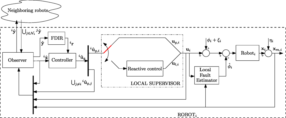
Figure 1. Overall schema of the distributed fault-tolerant control strategy.
The paper is organized as follows. Section 2 summarizes some basic notation of the vectors used in the rest of the paper. Section 3 introduces the modeling of the single robot, of the collective system, and of the intra-robots communication. Section 4 presents the decentralized observer-controller scheme, and it discusses the convergence analysis of the observer errors. Section 5 describes the fault detection and isolation algorithm, and the recovery strategy. Section 6 shows the results of numerical simulations and, finally, Section 7 presents some conclusions and future works.
2. Notation
Let us introduce the some basic notation adopted throughout the rest of the paper. The generic variable relative to the i-th robot will be denoted as vi, while the corresponding collective variable, i.e., a stacked vector collecting the variables vi for all the robots, will be denoted without any subscript/superscript; namely, where N is the number of robots. The estimate of collective variable v locally made by the i-th robot is denoted as , while the collection of the estimation vectors of the different robots is denoted as . The estimation error performed by i-th robot is denoted as , while the collection of the estimation errors of the different robots is expressed as . Finally, the vector v* represents where 1N is the (N × 1) vector of ones and ⊗ denotes the Kroneker product operator.
3. Modeling
Let us consider a multi-robot system composed of N robots, each of them characterized by the following dynamics (i = 1, 2, …, N)
where xi ∈ ℛn and ui ∈ ℛn denote, respectively, the i-th robot’s state and input, i ∈ ℛn is an additive actuator fault term that is zero in healthy conditions and i(t, xi) ∈ ℛn is a term collecting the model uncertainties and disturbances. The following assumptions on the single robot’s model hold:
assumption 1. The model uncertainties ξi(t, xi) are assumed to be norm bounded by a known constant term , assumed equal for each robot, i.e.,
assumption 2. Each robot has direct access only to a noisy measure xm,i of its own state, i.e.,
where ηi ∈ ℛn is the measurement additive noise supposed to be norm bounded by a known positive scalar , assumed equal for each robot, i.e.,
Let us define the collective variables of the system as the vectors collecting the variables of all the robots of the network, as
On the basis of the single robot dynamics [equation (1)], the collective dynamics is expressed as
while the collective noisy measurement of the system state is
3.1. Communication Modeling
As common in multi-robot systems [see, e.g., Godsil and Royle (2001), Fax and Murray (2004), and Olfati-Saber and Murray (2004)], the information exchange among the robots can be modeled referring to graph theory approaches. Indeed, the robot network can be described as a graph characterized by its topology, where 𝒱 is a set of indexes labeling the N vertices (nodes) representing the robots, and is the set of edges (arcs) representing the communications between robots; i.e., robot i and robot j can communicate only if there is an arc between node i and node j. Thus, the i-th robot receives information only from its neighbors . The cardinality of is the in-degree of node i, i.e., . Moreover, the cardinality of the set of nodes receiving information from node i represents the out-degree of node i, i.e., . If all the communication links among the robots are bi-directional, the graph is called undirected (i.e., (i, j) ∈ ℰ ⇒ (j, i) ∈ ℰ) otherwise, the graph is called directed. An undirected graph is called connected if there is an undirected path between every pair of distinct nodes. A directed graph is called strongly connected if any two distinct nodes of the graph can be connected via a directed path, i.e., a path that follows the direction of the edges of the graph. A node of a directed graph is named balanced if its in-degree and its out-degree are equal; a directed graph is called balanced if each node of the graph is balanced. Any undirected graph is balanced.
From the mathematical point of view, the graph topology can be represented by the (N × N) adjacency matrix
where aij = 1 if there exists an arc from vertex j to vertex i. Adiacency matrix is symmetric in the case of undirect graph. The communication topology can be also characterized by the (N × N) Laplacian matrix (Ren and Beard, 2008; Mesbahi and Egerstedt, 2010) defined as
The Laplacian matrix has some useful properties that make it very popular in the field of multi-robot systems and that will be exploited in the following paper. More in detail, all the eigenvalues of the matrix L have real parts equal to or greater than zero (i.e., Re(λi) ≥ 0, ∀i); moreover, L exhibits at least one zero eigenvalue with the N × 1 vector of all ones 1N as the corresponding right eigenvector. It holds that rank(L) ≤ N − 1, in particular it results rank(L) = N − 1 if and only if the directed graph is strongly connected. The N eigenvalues of L can be ordered such that
thus, Re(λ2) is greater than zero if and only if the graph is strongly connected; for this reason, λ2 is defined as the algebraic connectivity of the graph. For a balanced directed graph (and, thus, for an undirected graph), 1N is also a left eigenvector of L, i.e., . Finally, if the graph is undirected, the Laplacian is symmetric and positive semidefinite.
The following assumptions about the communication hold:
• each robot does not know the topology of the overall communication graph but it only knows who are its neighbors.
• the graph topology is assumed fixed, i.e., there are no communication links that can appear or disappear over the time.
4. Decentralized Observer-Controller Scheme
The robots are required to achieve a global mission, i.e., a mission depending on the collective state x of the overall team. However, since the collective state measurement is not available to the robots, a distributed observer-controller scheme is adopted in which, for each robot, a local observer provides a local estimate of the collective state, ; then, the controller computes the robot input in a pseudo-centralized manner on the base of the estimated collective state (Antonelli et al., 2013, 2014; Arrichiello et al., 2015).
In addition to the global mission, each robot must achieve also local (reactive) tasks to take into account unexpected events such as the presence of obstacles along its path. The switching between global behavior and reactive behavior is handled by a Local Supervisor according to the current scenario.
4.1. Nominal Control Input
The control input of the i-th robot has the following form
where is the control input that allows to achieve the global task, depending on the estimate of the collective input, while (k = 1, …, mi) are a set of mi local reactive control inputs, and . The parameters αi,h (h = 0, …, mi) are scalar gains such that:
• ;
• ;
in other words, at each time instant only one of them is 1 and all the others are equal to 0. Thus, the input terms on the right side of equation (8) are mutually exclusive control inputs, and each robot selects the value of gains αi,h on the basis of its own state and of the external environment.
4.1.1. The Global Mission Controller
In the proposed approach, the global objective for the team of robots is expressed via a task function depending on the collective state as
where is a constant matrix; thus,
A common example of global tasks of this form is that of assigning desired time-varying references to the team centroid and the relative formation. In this case, the task function becomes
where , σ1 and σ2 are the centroid and formation task functions defined as:
with the corresponding Jacobian matrix (Antonelli et al., 2013);
with the corresponding Jacobian matrix (Antonelli et al., 2013). A centralized solution for such kind of global task can be obtained by computing the global collective input ug as
where σd is the desired value of the task function, is the task error, is the pseudo-inverse of the Jacobian matrix, and kc is a constant positive gain.
In a distributed scenario, since the single robots do not know the collective state of the system, each of them uses its collective state estimate in order to compute an estimate of the collective input as
where is the estimate of the task error.
Then, the robot i computes its own input in equation (8) selecting the relative component from , i.e.,
where Γi is the (n × Nn) selection matrix that extracts the components of the i-th robot from a collective vector
4.1.2. The Local Reactive Behavior
A part from collaborating with the teammates to achieve the global mission, each robot is responsible of its own safety. This means that it can activate, if necessary, reactive behaviors, e.g., to prevent obstacles along its path. Reactive behaviors are local control inputs that are activated and deactivated by a local supervisor depending only on the robot own state, xi, and on information from onboard sensors (e.g., cameras, rangefinders, etc.). As an example, in the presence of an obstacle in the advancing direction, the goal of the obstacle avoidance reactive task is that of computing an input ul,1 aimed at keeping the robot at a safe distance, d > 0, from the obstacle, whose position, , can be obtained by onboard sensors. Therefore, the task function can be written as
where Jl,1 is the task Jacobian matrix, and
is the unit vector aligned with the obstacle-to-vehicle direction. According to null space-based behavioral control approach presented in Antonelli et al. (2008), the obstacle avoidance is obtained by means of the following expression of
where θ1 is a positive scalar gain. Thus, when an obstacle is detected by robot i and it is closer than a threshold value, the local supervisor activates the obstacle avoidance behavior (i.e., according to equation (8), it sets αi,1 = 1 and αi,0 = 0). Hence, the input to the robot i would become ui = ul,1. However, since by adopting the control input [equation (17)], the global task would be totally neglected, the local input can be improved by adding the global task as secondary task, in such a way the robot still tries to achieve it while avoiding the obstacle (primary task) (Antonelli et al., 2008). Thus, equation (17) can be replaced by
where the global input vector is projected into the null space of matrix Jl,1 by means of matrix
4.2. State Observer
As seen in Section 4.1.1, to compute the global input ug,i, each robot needs an estimate of the collective state. To this aim, the decentralized observer first proposed in Arrichiello et al. (2015) and then modified in Arrichiello et al. (2014c) can be adopted. In particular, the observer on board the generic robot i-th computes the estimate of the collective state x as follows
where y is an auxiliary variable defined as
that results useful both for state estimation and for diagnosis purposes discussed in the following section; ko is a positive scalar gain; Πi is the (Nn × Nn) matrix defined as , that selects only the components of the i-th robot;
where t0 is the initial time instant; takes into account the possibility to activate the reactive local control and it is given by
remark 4.1. It is worth highlighting that the definition of ym makes use of the real input [equation (16)] (global or reactive), while the estimate takes into account only the estimated global input for robots different from i-th and, thanks to the additive term Δ ui, the real input for the i-th robot. In this way, the reactive behaviors cannot be confused with faults by other robots in the team, despite they affect the global mission.
Moreover, the selection matrix Πi allows to select only the i-th components from global variables as y. This ensures that equation (19) can be implemented on a distributed system since each robot only uses variable components locally available.
Let us define the collective estimated variables
and the collective vectors
where ⊗ denotes the Kronecker product operator. By taking into account equations (19), (23), and (24), the collective state estimation dynamics is
where , and
The dynamics of the collective state estimation error is given by
In the previous works (Arrichiello et al., 2014c, 2015), it has been proven that with the observer [equation (25)], in the absence of faults, measurement noise, and model uncertainties, the collective state estimation error exponentially converges to the origin if no robots are adopting a reactive control (i.e., in equation (8) and ∀i).
To prove the convergence of , the exponential convergence to the origin of is first proven by the following theorem
theorem 1. In the presence of a strongly connected directed communication graph (or connected undirected graph) and in the absence of faults (ϕ = 0), measurement noise, and model uncertainties ( = ξ = 0), is exponentially convergent to the origin with the observer [equation (25)], independent from the local control input, ui (i = 1, …, N), applied by the robots. Furthermore, in the presence of bounded measurement noise and model uncertainty, is globally uniformly ultimately bounded.
Then, based on the previous theorem, also the convergence of in the absence of reactive behaviors is stated by the following.
theorem 2. In the presence of a strongly connected directed communication graph (or connected undirected graph) and in the absence of faults (ϕ = 0), measurement noise, and model uncertainties ( η = ξ = 0), with the observer in [equation (25)], the stacked vector of the collective state estimation errors is exponentially convergent to the origin. Moreover, in the presence of bounded measurement noise and model uncertainty, is globally uniformly ultimately bounded.
The complete proofs of both the theorems can be found in Arrichiello et al. (2014c) and Arrichiello et al. (2015) and they are not reported here for the sake of brevity.
remark 4.2. Different from , in the presence of reactive behaviors, the convergence of to zero cannot be guaranteed even in the absence of faults and disturbances, since does not converge to zero.
5. Fault Tolerant Strategy
In this section, we present the proposed strategy to handle recoverable and unrecoverable actuator faults occurring on any robot of the team. In the presence of a fault, the first step is to decide if the robot objective can be achieved in spite of its occurrence by opportunely reconfiguring the control input. In this case, it is possible to classify the fault as recoverable (Staroswiecki, 2008) (e.g., a bias between the commanded input and the actual one), and active fault-tolerant strategies can be locally activated by single robots, that locally modifies the nominal control law [equation (16)] so as to accommodate the fault by compensating the effects of the fault on its dynamics. Regarding non-recoverable faults (e.g., permanent actuator failure) active strategies are not available, but in multi-robot system the intrinsic redundancy can be exploited in order to define a passive fault tolerance strategy aimed at removing the faulty vehicle from the team and rescheduling the mission needs.
5.1. Recoverable Faults: Local Fault Estimate and Accommodation
In the presence of recoverable faults, an active fault tolerance approach is pursued, i.e., the nominal control law [equation (8)] is reconfigured by adding a compensation term, . Thus, the new input vector , given by
is adopted instead of equation (8). In equation (28), ui has the same form than in equation (8), while the adaptive term provides an estimate of the fault, in such a way to compensate its effect on the robot dynamics.
In order to estimate the fault ϕi, a local state observer is designed as in Arrichiello et al. (2014b) and Zhang et al. (2013)
where is a symmetric and positive definite gain matrix. The update law for the fault estimation is given by
where ei(t) = xi − zi and is a symmetric positive matrix gain to be designed.
remark 5.1. From equation (30), it can be recognized that the on-line fault estimator has the following expression
where tf,i is the fault occurrence instant. The integral term allows to achieve an asymptotic estimate of a constant fault while, in the presence of time-varying faults, it can be proven that the estimation error is bounded.
From the robot dynamics [equation (1)] and the new control law [equation (28)] with the update law [equation (30)], it holds
where is the fault estimation error. In the absence of faults, it can be easily seen that, in the absence of measurement noise ηi and disturbances ξi, the estimate is zero, provided that the initial observer error is zero. On the other side, in the presence of measurement noise and disturbances, the estimate is different from zero even in the absence of faults and converges to Kηi − ξi.
By introducing the collective vectors of errors e = and fault estimations , from equations (30) and (32) it holds
As reported in Section 4.2, the estimation error of the collective state coming from observer [equation (25)], without local fault estimation [equation (30)], is exponential convergent to zero in the absence of faults, disturbances, and measurement noise and under the assumption of a connected undirected graph, while in the presence of bounded disturbances and measurement noise, is globally uniformly ultimately bounded (Arrichiello et al., 2014b, 2015).
In the presence of a recoverable fault and the adaptive fault observer [equation (29)] with the update law [equation (30)], it has been proven in Arrichiello et al. (2014b) that, under the assumptions of connected undirected communication graph and fault velocity bounded with a known bound, the estimation errors , , and are all uniformly ultimately bounded, as well as the task-tracking errors (l = 1, 2). Here, the proof is not reported for the sake of brevity.
5.2. Non-Recoverable Faults
In the presence of non-recoverable faults, the intrinsic redundancy of a multi-robot system is exploited in order to accomplish the mission in spite of the faulty teammates. To this aim, a passive fault tolerance strategy is designed aimed at removing the faulty robots from the team, and at allowing the remaining vehicles to reconfigure themselves. To this purpose, a two-stage procedure is designed: at first, a fault detection and isolation strategy, developed as in Arrichiello et al. (2015) and reported in the following for the sake of completeness, is adopted to make each robot able to detect the occurrence of a fault and to recognize the faulty vehicle even if not in direct communication; then, the faulty vehicle is removed from the team by suitably resizing the exchanged vectors.
5.2.1. Fault Detection and Isolation
In order to detect the occurrence of a fault and isolate the faulty vehicle, let us define the following residual vector for the i-th robot (Arrichiello et al., 2015)
it is worth noticing that the computation of the above quantity does not require additional information exchange since it makes use of the same terms used by the state observer [equation (19)]. The vector ir can be seen as a stacked vector, i.e., , where each component represents the residual computed by robot i relative to robot k and allows the robot i to monitor the healthy state of robot k. After some algebraic manipulations [see Arrichiello et al. (2015) for details], it is possible to rewrite the residual component irk as the sum of two contributions: the first term, ihk, depending on the observer dynamics and on the presence of noise and disturbances; the second term, ifk, depending on the fault ϕk, i.e.,
with
where vector collects the estimation errors of all the observers, and .
From equations (37) to (38), it can be argued that each residual component irk, i = 1, 2, …, N, is sensitive only to fault occurring on robot k and is insensitive to all the other faults [see Arrichiello et al. (2015) for details]. Thus, a fault ϕk affecting the robot k is detected and isolated by the robot i if
where tf > 0 is the instant at which the fault occurs and iμj(t) (∀i,j) are suitable adaptive thresholds. The use of thresholds is necessary to avoid false alarms since, due to the measurement noise and model uncertainties, the residuals are always different from zero even in the absence of faults. In Arrichiello et al. (2015), the following expression for iμk has been derived
where iδk is 1 if i = k and 0 otherwise, and are the bounds defined in equations (2) and (4), while κ an λ are positive scalars such that
that always exist since is Hurwitz.
remark 5.2. It is worth noticing that, in the presence of a recoverable fault on robot l, residuals irl, i = 1, 2, …, N, can exceed their threshold during the transient phase needed to the adaptive term in equation (30) to converge to the fault. To avoid these false alarms, the decision about a fault can be taken only if the thresholds is exceeded for a certain time window. This is a quite standard approach in decision-making scheme design, see, e.g., Pierri et al. (2008) for further details.
5.2.2. Fault Recovery via Exclusion of the Faulty Vehicle
In order to accomplish the team mission in spite of the presence of a non-recoverable fault, the faulty vehicle must be excluded from the team and the task function references must be replanned. The adopted detection and isolation strategy allows each robot to isolate the faulty teammate but, since each robot detects the fault asynchronously from each other, the problem is to determine the time instant from which the faulty vehicle must be excluded.
More in detail, the exclusion of a faulty vehicle requires each robot to change the dimension of all the involved variables; that is, each healthy robot must resize the estimate of the collective state vector (), the input vector (), and the auxiliary variable vector that is exchanged with the neighbors. The vectors’ dimensions become (N − 1)n instead of Nn.
Since the detection time instant t in equation (39) is different for each robot, problems can arise if the vector resizing is not synchronized. For example, let us suppose that the ith vehicle has detected a fault on robot lth (i.e., exceeds the thresholds iμl) at time ti, and it resizes the vector to be sent to its neighbors. Supposing that one or more of these neighbors has not yet detected the fault, they would receive a reduced size vector from the neighbor i but they have not any information about the faulty teammate, so they do not know which components to remove from their collective state estimate. To avoid this issue, all the robots must have already detected and isolated the faulty vehicle before starting to exchange the reduced size vector. To this purpose, let us define the time itd as the first instant at which in equation (39), i.e.,
and the detection delay of robot i, iΔtd = itd − tf, as the time occurring from the fault occurrence and its detection/isolation by vehicle ith.
Based on the previous considerations, the following steps for removing the faulty robot have to be developed:
• each robot estimates the maximum detection delay, i.e.,
• the first robot that detects the fault occurrence sends the reduced size vectors starting from time jtd + Δtd,max,
• the other robots, once received the reduced-order vector , have already complete knowledge about the faulty robot and can resize correctly their own estimates.
In sum, the resize of the estimates of the collective variables is possible after the time instant
Thus, the problem is how to get a reliable estimate of Δtd,max.
5.2.3. Estimate of the Maximum Detection Delay
In order to estimate Δtd,max, a detection time analysis should be performed. In general, the detection time depends both on the fault dynamics and on the residuals dynamics. First of all, let us consider, on the base of equation (36), that the part of the residual not depending by the fault is below its threshold, i.e. , and thus, in the presence of a fault, the following chain of inequalities can be written
The fault detection by the robot i occurs if , hence, from equation (44) a sufficient detectability condition can be defined as
and thus
Equation (46) could be adopted to compute an estimate of the maximum detection time and, thus, of Δtd,max. Such an estimate will be quite conservative since it is based on a sufficient detectability condition and on thresholds also computed from conservative bounds. However, since the fault dynamics is included in equation (46), it is not possible to have an estimate of Δtd,max valid for any possible fault, but a time detection analysis can be made only for limited class of faults. More in detail, a possible solution for this problem has been developed in Arrichiello et al. (2014a), where the maximum detection delay was computed for constant faults. By using the same arguments as in Arrichiello et al. (2014a) and the results in Keliris et al. (2013), the time detection analysis can be easily extended to other faults ϕi, provided that for a time sufficient for the fault detection, with opportunely large.
6. Numerical Simulations
In this section, we present a numerical simulation case study where a team of 4 robots (N = 4), using the proposed distributed fault-tolerant control approach, moves in a plane (n = 2) keeping an assigned formation. During the execution of the mission some of the robots are subject to recoverable faults, unrecoverable faults, as well as reactive behavior activations due to obstacle avoidance.
Gains kc, ko, K, and G in equations (15), (19), (29), and (30) were, respectively, set to kc = 4, ko = 6, K = 3I2, and G = 0.01I2. The measurement noise ηi in equation (3) is assumed to be bounded by 0.001 m , while the process noise in equation (1) is bounded by 0.005 m/s ( in equation (2)). The directed network topology shown in Figure 2 is assumed for the information exchange.
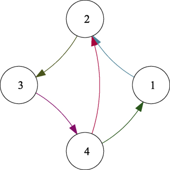
Figure 2. Communication graph.
The desired path of the centroid σ1,d(t) is reported in Figure 3 (dashed blue line), while the desired formation σ2,d(t) is constant and it corresponds to a regular polygon formation of side 0.5 m around the desired centroid. During the simulation, two faults of different nature are considered. In detail, a recoverable fault occurs on robot 2 at tf,2 = 19 s and it has the following expression:
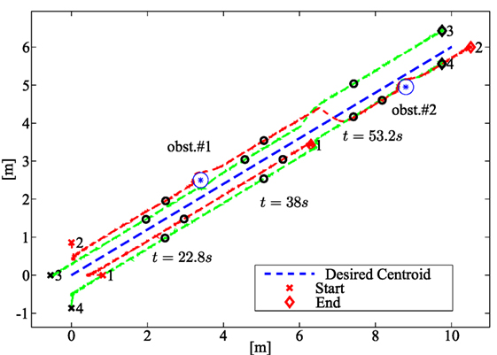
Figure 3. Path followed by the robots in the numerical case study. The dashed green and red lines, respectively, show the paths of healthy vehicles and vehicles subject to faults; the blue line represents the desired centroid path. The team configuration at three intermediate instants 22.8, 38, and 53.2 s is shown (black circles) together with the initial (crosses) and final (diamonds) configurations.
A non-recoverable fault on robot 1, consisting in a complete stop of the robot, is assumed occurring at tf,1 = 41.8 s. The vehicle paths are shown in Figure 3 (green dashed lines for healthy robots 3 and 4, and red lines for robots 1 and 2 subject to faults). Figure 4 shows the components of and its estimate performed by the local fault estimator on board robot 2; the figure also shows that, depending on the local observer gains, the measurement and process noise affects the fault estimates. In this sense, based on equation (1) the process noise is seen as a (bounded) fault affecting the robot dynamics.
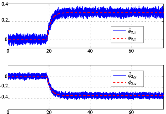
Figure 4. Fault ϕ2 on vehicle 2 starting at instant tf,2 = 19 s and its estimation 2.
Figure 5 shows the residuals calculated by each robot of the team and relative to the faulty robot 1. In detail, the residual norms (i = 1, 2, 3, 4) (continuous blue lines) and the corresponding thresholds (dashed green lines) are plotted. The plots also show that, being the fault unrecoverable, all the residuals are kept below the corresponding threshold as long as the fault is not affecting the robot, while the residuals computed by each robot overcome the thresholds after the fault occurrence even if the faulty robot has not a direct communication link with all the teammates.
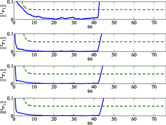
Figure 5. Norm of residuals ir1 (i = 1, 2, 3, 4) (solid lines) as calculated by vehicle i and relative to vehicle 1 subject to unrecoverable fault at tf,1 = 41.8 s. Dashed green lines are the corresponding thresholds used for FDIR strategy.
Figures 6–8 show that the residuals relative to other robots, namely, (i = 1, 2, 3, 4 and j ≠ 1), do not overcome the corresponding thresholds; this means that no fault is detected on robots 2, 3, 4. In particular, with regard to robot 2, that is affected by a recoverable fault after tf,2 = 19 s, the residuals do not overcome the threshold since the fault is locally compensated by the controller according to the strategy in Section 5.1, and it does not need to be globally detected and recovered.
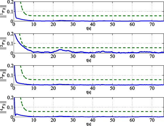
Figure 6. Norm of residuals ir2 (i = 1, 2, 3, 4) (solid lines) as calculated by vehicle i and relative to the vehicle 2 subject to a recoverable fault at tf,2 = 30.4 s. Dashed green lines are the corresponding thresholds used for FDIR strategy.
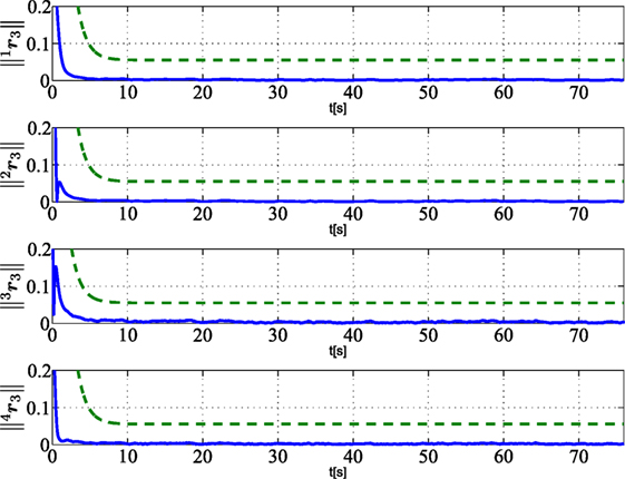
Figure 7. Norm of residuals ir3 (i = 1, 2, 3, 4) (solid lines) as calculated by vehicle i and relative to the healthy vehicle 3. Dashed green lines are the corresponding thresholds used for FDIR strategy.
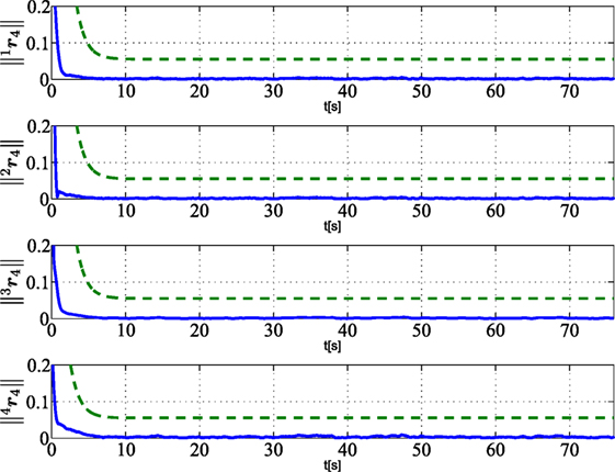
Figure 8. Norm of residuals ir4 (i = 1, 2, 3, 4) (solid lines) as calculated by vehicle i and relative to the healthy vehicle 4. Dashed green lines are the corresponding thresholds used for FDIR strategy.
It is worth noticing from Figure 3 that the robots are also able to avoid obstacles along their paths via the activation of local reactive behaviors, and that, as shown in Figures 5–8, the activation of the local behaviors do not effect the residual components. Concerning the FDIR strategy described in Section 5.2.2, Figure 3 shows that, after the exclusion of robot 1, the formation is rearranged according to a regular triangular formation. The maximum detection time Δtd,max in equation (42) is set to 5 s.
In Figure 9, the norms of the state estimation error (top) and the task errors and (bottom) are shown. The figure shows that these errors grow during the obstacle avoidance and the fault detection phases and decreases toward a neighborhood of the origin in normal conditions. Finally, Figure 10 reports the control input ui (∀i) in equation (1). The top plot is relative to robot 1 that is affected by a non-recoverable fault; thus, the input becomes zero after the fault occurrence. Concerning the other plots, the discontinuities on the inputs is due to the faulty robot exclusion and formation rearrangement.
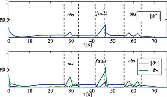
Figure 9. (Top) Norm of the state estimation error ; (Bottom) norm of the task errors 1||(green line) and 2 || (blue line). Dashed black lines are in correspondence of activation/deactivation of obstacle avoidance reactive behavior, occurrence of unrecoverable fault at tf,1 and faulty vehicle removal.
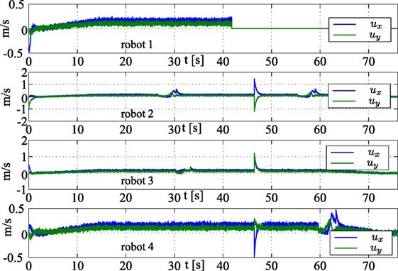
Figure 10. Control input ui in equation (1) ∀i.
7. Conclusion
In this paper, a distributed fault-tolerant control strategy for networked robots was presented. The proposed approach builds on a distributed controller-observer architecture, a fault detection, isolation and recovery strategy for unrecoverable faults, and a local fault estimation and compensation for recoverable faults. The proposed approach also results robust to the activation of reactive behaviors acting at local levels and not included in the global control strategy.
The proposed architecture allows to manage in an integrated manner the different issues related to distributed formation control and fault management, while keeping limited the communication burden; i.e., the information exchanged among neighbors for state estimation purposes are also used for fault management without further requirements. The approach was successfully tested via numerical simulations, and the results of a single integrated case study involving the occurrence of the different kinds of faults as well as the activation of reactive behaviors was presented to validate the approach.
Author Contributions
All authors listed have made substantial, direct, and intellectual contribution to the work and approved it for publication.
Conflict of Interest Statement
The authors declare that the research was conducted in the absence of any commercial or financial relationships that could be construed as a potential conflict of interest.
References
Antonelli, G., Arrichiello, F., Caccavale, F., and Marino, A. (2013). A decentralized controller-observer scheme for multi-agent weighted centroid tracking. IEEE Trans. Aut. Control 58, 1310–1316. doi: 10.1109/TAC.2012.2220032
Antonelli, G., Arrichiello, F., Caccavale, F., and Marino, A. (2014). Decentralized time-varying formation control for multi-robot systems. Int. J. Robot. Res. 33, 1029–1043. doi:10.1177/0278364913519149
Antonelli, G., Arrichiello, F., and Chiaverini, S. (2008). The null-space-based behavioral control for autonomous robotic systems. J. Intell. Service Robot. 1, 27–39. doi:10.1007/s11370-007-0002-3
Arrichiello, F., Marino, A., and Pierri, F. (2014a). “A decentralized fault tolerant control strategy for multi-robot systems,” in Proceedings 19th World Congress of the International Federation of Automatic Control (Cape Town, South Africa), 6642–6647.
Arrichiello, F., Marino, A., and Pierri, F. (2014b). “Distributed fault detection and recovery for networked robots,” in IEEE/RSJ International Conf. on Intelligent Robots and Systems (Chicago, IL), 3734–3739.
Arrichiello, F., Marino, A., and Pierri, F. (2014c). “Distributed fault-tolerant strategy for networked robots with both cooperative and reactive controls,” in 2014 IEEE International Conference on Information and Automation (ICIA) (Harbin, China: IEEE), 677–682.
Arrichiello, F., Marino, A., and Pierri, F. (2015). Observer-based decentralized fault detection and isolation strategy for networked multirobot systems. IEEE Trans. Control Syst. Technol. 23, 1465–1476. doi:10.1109/TCST.2014.2377175
Belta, C., and Kumar, V. (2004). Abstraction and control of groups of robots. IEEE Trans. Robot. 20, 865–875. doi:10.1109/TRO.2004.829498
Bullo, F., Cortés, J., and Martínez, S. (2009). Distributed Control of Robotic Networks. Applied Mathematics Series. Princeton, NJ: Princeton University Press.
Caccavale, F., Marino, A., Muscio, G., and Pierri, F. (2013). Discrete-time framework for fault diagnosis in robotic manipulators. IEEE Trans. Control Syst. Technol. 21, 1858–1873. doi:10.1109/TCST.2012.2212196
Cao, M., Morse, A. S., and Anderson, B. D. (2008). Reaching a consensus in a dynamically changing environment: a graphical approach. SIAM J. Control Optim. 47, 575–600. doi:10.1137/060657005
Davoodi, M., Khorasani, K., Talebi, H., and Momeni, H. (2014). Distributed fault detection and isolation filter design for a network of heterogeneous multiagent systems. IEEE Trans. Control Syst. Technol. 22, 1061–1069. doi:10.1109/TCST.2013.2264507
Dong, X., and Hu, G. (2016). Time-varying formation control for general linear multi-agent systems with switching directed topologies. Automatica 73, 47–55. doi:10.1016/j.automatica.2016.06.024
Fax, J., and Murray, R. (2004). Information flow and cooperative control of vehicle formations. IEEE Trans. Automatic Control 49, 1465–1476. doi:10.1109/TAC.2004.834433
Ferrari, R., Parisini, T., and Polycarpou, M. (2009). Distributed fault diagnosis with overlapping decomposition: an adaptive approximation approach. IEEE Trans. Automatic Control 54, 794–799. doi:10.1109/TAC.2008.2009591
Godsil, C., and Royle, G. (2001). Algebraic Graph Theory. Graduate Texts in Mathematics. New York: Springer.
Hong, Y., Chen, G., and Bushnell, L. (2008). Distributed observers design for leader-following control of multi-agent networks. Automatica 44, 846–850. doi:10.1016/j.automatica.2007.07.004
Keliris, C., Polycarpou, M. M., and Parisini, T. (2013). A distributed fault detection filtering approach for a class of interconnected continuous-time nonlinear systems. IEEE Trans. Automat. Contr. 58, 2032–2047. doi:10.1109/TAC.2013.2253231
Marino, A., and Pierri, F. (2015). “Discrete-time distributed control and fault diagnosis for a class of linear systems,” in IEEE/RSJ International Conf. on Intelligent Robots and Systems (IROS) (Hamburg, Germany), 2974–2979.
Marino, A., Pierri, F., Chiacchio, P., and Chiaverini, S. (2015). “Distributed fault detection and accommodation for a class of discrete-time linear systems,” in Proceeding of the IEEE International Conf. on Information and Automation, (Lijiang, China), 469–474.
Mesbahi, M., and Egerstedt, M. (2010). Graph Theoretic Methods in Multiagent Networks. Princeton, NJ: Princeton University Press.
Meskin, N., and Khorasani, K. (2009). Actuator fault detection and isolation for a network of unmanned vehicles. IEEE Trans. Automatic Control 54, 835–840. doi:10.1109/TAC.2008.2009675
Olfati-Saber, R., Fax, J., and Murray, R. (2007). Consensus and cooperation in networked multi-agent systems. Proc. IEEE 95, 215–233. doi:10.1109/JPROC.2006.887293
Olfati-Saber, R., and Murray, R. (2004). Consensus problems in networks of agents with switching topology and time-delays. IEEE Trans. Automatic Control 49, 1520–1533. doi:10.1109/TAC.2004.834113
Pierri, F., Paviglianiti, G., Caccavale, F., and Mattei, M. (2008). Observer-based sensor fault detection and isolation for chemical batch reactors. Eng. Appl. Artif. Intell. 21, 1204–1216. doi:10.1016/j.engappai.2008.02.002
Ren, W., and Beard, R. (2008). Distributed Consensus in Multi-vehicle Cooperative Control. Communications and Control Engineering. Berlin: Springer.
Smith, R., and Hadaegh, F. (2007). Closed-loop dynamics of cooperative vehicle formations with parallel estimators and communication. IEEE Trans. Automatic Control 52, 1404–1414. doi:10.1109/TAC.2007.902735
Stankovic, S., Ilic, N., Djurovic, Z., Stankovic, M., and Johansson, K. (2010). “Consensus based overlapping decentralized fault detection and isolation,” in Conf. on Control and Fault-Tolerant Systems (Nice, France), 570–575.
Staroswiecki, M. (2008). On fault handling in control systems. Int. J. Control Automation Syst. 6, 296–305.
Tuna, S. E. (2008). Synchronizing linear systems via partial-state coupling. Automatica 44, 2179–2184. doi:10.1016/j.automatica.2008.01.004
Wang, J., Cheng, D., and Hu, X. (2008). Consensus of multi-agent linear dynamic systems. Asian J. Control 10, 144–155. doi:10.1002/asjc.15
Wang, Y., Ye, H., Ding, S., Cheng, Y., Zhang, P., and Wang, G. (2009). Fault detection of networked control systems with limited communication. Int. J. Control 82, 1344–1356. doi:10.1080/00207170802558967
Yang, P., Freeman, R., and Lynch, K. (2008). Multi-agent coordination by decentralized estimation and control. IEEE Trans. Automatic Control 53, 2480–2496. doi:10.1109/TAC.2008.2006925
Yu, W., Chen, G., Cao, M., and Kurths, J. (2010). Second-order consensus for multiagent systems with directed topologies and nonlinear dynamics. IEEE Trans. Syst. Man Cybern. B Cybern. 40, 881–891. doi:10.1109/TSMCB.2009.2031624
Zhang, K., Jiang, B., and Shi, P. (2013). Observer-Based Fault Estimation and Accomodation for Dynamic Systems. Berlin, Heidelberg: Springer.
Zhang, X., Polycarpou, M., and Parisini, T. (2002). A robust detection and isolation scheme for abrupt and incipient faults in nonlinear systems. IEEE Trans. Automatic Control 47, 576–593. doi:10.1109/9.995036
Keywords: networked robots, multi-robot systems, fault-tolerant control, distributed control, fault detection
Citation: Arrichiello F, Marino A and Pierri F (2017) Distributed Fault-Tolerant Control for Networked Robots in the Presence of Recoverable/Unrecoverable Faults and Reactive Behaviors. Front. Robot. AI 4:2. doi: 10.3389/frobt.2017.00002
Received: 06 October 2016; Accepted: 17 January 2017;
Published: 21 February 2017
Edited by:
Yongping Pan, National University of Singapore, SingaporeReviewed by:
Qiuxuan Wu, Hangzhou Dianzi University, ChinaMohamed Hamdy, Menoufia University, Egypt
Xiwang Dong, Beihang University, China
Copyright: © 2017 Arrichiello, Marino and Pierri. This is an open-access article distributed under the terms of the Creative Commons Attribution License (CC BY). The use, distribution or reproduction in other forums is permitted, provided the original author(s) or licensor are credited and that the original publication in this journal is cited, in accordance with accepted academic practice. No use, distribution or reproduction is permitted which does not comply with these terms.
*Correspondence: Filippo Arrichiello, Zi5hcnJpY2hpZWxsb0B1bmljYXMuaXQ=