 Xiaojiao Chen
 Dehao Duanmu1
- 1Department of Mechanical Engineering, The University of Hong Kong, Hong Kong, China
- 2Department of Mechanical and Energy Engineering, Southern University of Science and Technology, Shenzhen, China
Soft robotics has widely been known for its compliant characteristics when dealing with contraction or manipulation. These soft behavior patterns provide safe and adaptive interactions, greatly relieving the complexity of active control policies. However, another promising aspect of soft robotics, which is to achieve useful information from compliant behavior, is not widely studied. This characteristic could help to reduce the dependence of sensors, gain a better knowledge of the environment, and enrich high-level control strategies. In this paper, we have developed a state-change model of a soft robotic arm, and we demonstrate how compliant behavior could be used to estimate external load based on this model. Moreover, we propose an improved version of the estimation procedure, further reducing the estimation error by compensating the influcence of pressure deadzone. Experiments of both methods are compared, displaying the potential effectiveness of applying these methods.
1 Introduction
The realm of soft robotics is an ideal safe solution when dealing with collision and interaction due to compliant behavior Laschi et al. (2016); Majidi (2013); Kim et al. (2013). The properties of compliant behavior include intrinsic deformable structures Yi et al. (2018); Suarez et al. (2018), soft materials Yi et al. (2017); Polygerinos et al. (2015b); Wang et al. (2017), and backdrivable actuation methods. Various ways of achieving softness have been studied, including methods relying on compliant elements like SEA Pratt and Williamson (1995), memory effects like SMA Mohd Jani et al. (2014), dielectric elastomers like DEA O’Halloran et al. (2008), and pneumatic driven methods like PAMs Tondu and Lopez (2000) and pneu-nets Mosadegh et al. (2014). The realm of soft robotics has been actively inventing all kinds of soft machines to exploit their compliant nature in many aspects, such as soft arms that are safe to interact with Chen et al. (2017): Chen et al. (2018); Malzahn and Bertram (2014), soft fishes that swim naturally Marchese et al. (2014), soft gloves for rehabilitation Polygerinos et al. (2013, Polygerinos et al. (2015a), and soft hands that are versatile for handling objects Zhou et al. (2018); Zhou et al. (2019); Zhou et al. (2020).
The other potential use of softness is to gain valuable information from compliant behavior. There exist several examples that utilize compliant behavior to gain environmental information in the real world. For example, a human could estimate the weight of an object based on visual information of the deformation. The soft robots are also intelligence-embedded agents. They could not only handle local interaction compliantly but also store process information that may be helpful Laschi and Cianchetti (2014). One important aspect is the ability to estimate the force or load under interaction. However, it is not easy for soft robots to extract useful information from compliant behavior.
One way to achieve estimation from compliant behavior is to learn from data. In Wang and Wang (2020), the pressure information of a soft gripper was used to learn the external force. In Fang et al. (2019), local Gaussian regression was used to control and compensate for the external disturbance. However, the difficulty of using learning methods is a dependency on large data sets. Another limitation is that this method is specific to the design and structure of the soft arm, which makes it difficult for purposes of extension.
Another way is to establish models of the soft arm that involves external forces. However, it is not easy to achieve an accurate model for soft arms due to the softness of materials and complex description of the compliant body curves. Previously, most research has focused on kinematic models for controlling the soft arm statically based on the Constant Curvature assumption Jones and Walker (2006); Webster and Jones (2010); Bajo et al. (2011). Recently, there has been much improvement to the evolution of developing dynamic models for the soft arm. In Santina et al. (2019); Della Santina et al. (2020); Katzschmann et al. (2019); Wang et al. (2020), a dynamically-equivalent rigid robot is used to develop the dynamic model of the soft arm. Traditional rigid robot control methods could be well suited to this method. However, the difficulty of using this method is building an equivalent rigid robot in three-dimensional space faithfully. The resultant rigid counterpart is a hyper-redundant robot, and it is difficult to tackle. In Falkenhahn et al. (2015); Falkenhahn et al. (2017), the Euler-Lagrange method was used to derive the full dynamics. However, this method is quite complex and demands the accurate modeling of every part of the arm. In neither of these cases have these methods tackled the problem of estimating the external payload using their models.
In this paper, we have proposed a simplified analytical model and show how it could be used to control the arm and to extract loading information from compliant behavior. Our model captures the essential relationship between the pressure and the posture, establishing a preliminary relationship between the actuation space and the configuration space and providing a feed-forward control part. Based on this model, a state-change model is also derived by eliminating common modeling errors, and it is capable of estimating the external load from the change of bending angle. Furthermore, an improved method is given, accounting for the realistic pressure control deadzone and achieving a better estimation result with reduced error.
This paper does the following:
• We demonstrate the effectiveness of using a simplified model to control the soft arm in open loop.
• We propose a state-change model that avoids the negative mass problem.
• We are the first to consider the pressure deadzone effect, and we propose an improved method for the compensation, greatly improving the estimation result.
• We experimentally shown the performance of the state change model and the improved method.
The paper is organized as follows. First, the model and control of the soft robotic arm are given in Section 2. In Section 3, the state-change model and the improved method is derived and discussed. The experiments are analyzed in Section 4.
2 Extensible Soft Arm
2.1 Design of the Soft Arm
The soft robotic arm used in this paper is made up of six long bellows that have been installed in parallel. The relative positions of the bellows are constrained by two thin carbon-fiber plates, which avoids the potential buckling problem. Two acrylic plates are used as the connecting plates that force the bellows to share common starting and ending planes, as seen in Figure 1A.
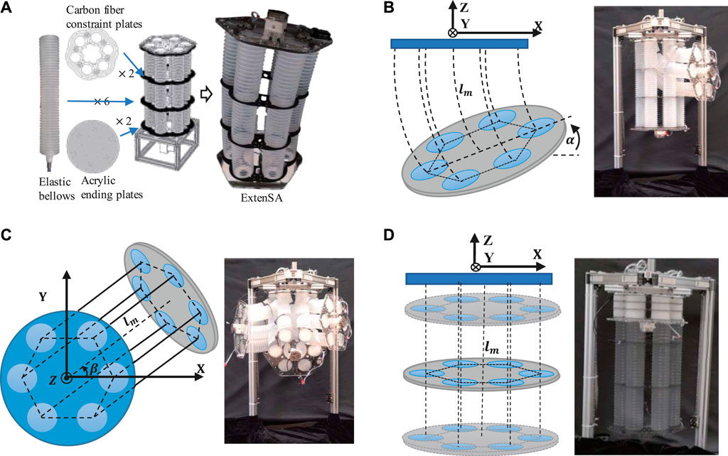
FIGURE 1. (A) The Design concept of ExtenSA. (B) The bending motion of ExtenSA
The soft arm is actuated by inflating and vacuuming through on-off valves. The pressure distribution inside the six bellows controls the posture of the arm. When the pressures of the bellows was not equal, the arm would bend toward the direction of the smaller pressure sum. The greater the difference, the greater the degree of the bend, as seen in Figure 1B. The rotation around the vertical axis is achieved based on adjusting the direction of the pressure difference, and a full circle range of 360∘ could be achieved, as seen in Figure 1C. As a backbone-less arm, this extensible soft arm has a very large elongation ratio. In the free state, the soft arm has a length of 400 mm. When the six bellows are pressurized equally, the arm would elongate to a maximum length of more than 500 mm; when depressurized equally, the arm would contract to a minimal length of around 100 mm, as shown in Figure 1D.
A possible application for this soft arm is to lift heavy weights for people or act as a piece of massage equipment due to its large force and great compliance.
2.2 Modeling the Soft Arm
A simplified static model of the soft arm is given here to provide a feed-forward control part for preliminary control. The method considers the force balance equations of the three general coordinates, which are the elongation, the bending, and the rotations. The bellow actuators are modeled as cylinders with internal spring terms. The damping term is not considered due to the quasi-static motion assumption, and the mass terms are neglected because of the relatively small value in this soft arm. A detailed derivation process can be seen in our previous paper Chen et al. (2019). Here, we give a brief description of the modeling result since this will be the basis of the following external load estimation method.
In the elongation direction, the output force is simply the sum of all the six pressure-generated forces and the spring forces written as
where F is the net output force,
In the bending and rotation direction, the torque generated by a certain bellow is given by its output force multiplied by its effective radius, given as
where T is the torque, with the subscript α and β to represents the bending and rotation respectively. R is the distance between the bellows’ center axis and the soft arm’s axis,
Combining Eqs. 1, 2, 3, we could express the configuration state of the soft arm by pressure information, which is given by
On the right side of Eq. 4, α represents the bending angle, β represents the rotation angle, and L represents the length of the central line of the soft arm. On the left side,
In the case of no external load at the plate, the expression could be further simplified into
One important usage of the above model is to control the soft arm. The right side of the equation is pressure-related information, representing the actuation space of the soft arm, while the left side of the equation is the bending, rotation, and elongation of the soft arm, representing the configuration space. Therefore, this model relates the actuation space to the configuration space of the soft arm, providing feed-forward terms to the control algorithms.
However, as this model could predict the soft arm’s movement to a certain degree, it is dangerous to use this model directly to estimate the external loads. This is because the unknown modeling error would be directly involved in the calculation, amplifying the estimation error, and, even worse, may cause the estimated mass to be negative.
We will therefore develop a state-change model based on this static model in Section 3, which would reduce the effect of the modeling error in the load estimation process.
2.3 Control of the Over-Actuated Soft Arm
The model could help to control the soft arm to the desired posture given commands like
Elongation movement is related to the pressure sums, and the bending and rotation are related to weighted pressure differences; given these constraints, we would like all the pressure commands to be as near the atmosphere as possible, without causing too much inflation or deflation.
Reorganize Eq. 5, we express the pressure related terms
We formulated the procedure of solving the pressure commands from configuration commands as a quadratic optimization problem:
where
This quadratic programming problem with linear constraints could be solved with a closed form result, which is given by
According to Eq. 8, given desired commands of the configuration space of the soft arm with L, α and β, the corresponding pressure commands in the actuation space could be obtained. By regulating the pressure commands, the soft arm could be controlled to the target position.
3 External Load Estimation
When external loads are exerted, the posture of ExtenSA would be changing passively to a balanced new state, as shown in From Figure 2. The
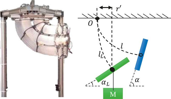
FIGURE 2. Loading Geometry of ExtenSA. The external load would exert a bending torque around the center fixing point of the arm as well as a pulling force along the center line of the arm, affecting the bending angle α and the length
The torque
Assume the arm is unloaded at a certain configuration and that a mass m is then attached at the end of the ending plate. The mass exerts a bending torque and a pulling force affecting both α and L. In the following context, we will denote the modeling values as
3.1 External Load Estimation with Original Model
Although the model Eq. 4 provides a preliminary relation between the actuation and configuration space, it is unacceptable to estimate the external payload directly using the model because the modeling error may render the estimated mass to be negative.
Together with Eq. 9, to get the mass estimation we need to solve the equation
Giving the estimation as
As modeling errors exist, it is possible that the term
3.2 External Load Estimation with State-Change Model
Although we could not predict the exact model errors during every task, they all had the same model error in common, either from the friction or the characteristics of the materials. This means it would be more accurate to predict the state change rather than to directly predict the state. In other words, a model predicting the state change instead of predicting the state may lead to more trustworthy results through reducing the effect of common errors, as shown in Figure 3.
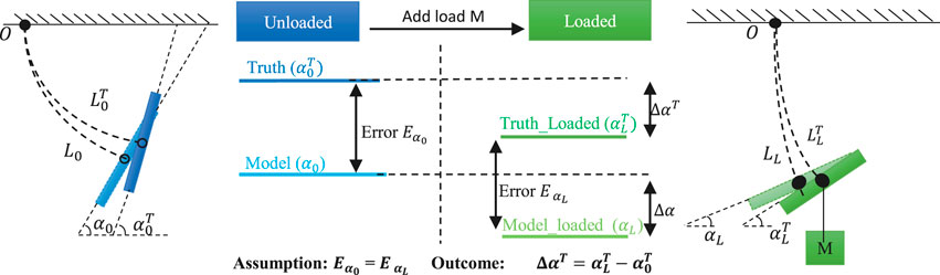
FIGURE 3. Payload Estimation Illustration of ExtenSA. With the information of angle measurement, the loaded model could be used to approximate the external loads.
Based on this assumption that the mean modeling error of the model is constant during a periodic task, we would like to derive a state-change model to estimate the external load, that is, to use the change of bending angle
Here, we define the value of
Looking into the process of loading, while the bending angle and length are changing, the pressures inside the bellows would not change due to low-level pressure feedback control if all the pressure commands are well controlled within a relatively small error region. Then, the three quantities,
To simplify the calculation, the approximation of
On the other hand, the approximation of
These two equations describe the state change of the ExtenSA, which could be used to compensate for the change of α and L due to external loads.
According to Eq. 13, the equation could be rewritten as
Giving m as
This equation avoids the involvement of pressure information, guaranteeing the acquisition of a positive estimation of the payload because the
Moreover, this equation not only applies to the situation where the soft arm is in a steady state. For a soft arm in a cyclic motion, such as when following a sinusoidal trajectory, this equation also works, with the value of
3.3 External Load Estimation with Improved Method
However, in reality, previous payload estimation methods may suffer from the ExtenSA’s pressure changing during the loading process, which is due to the pressure control deadzone, rendering decreased accuracy of the payload estimation. In this section, a modified method for payload estimation is proposed to improve the accuracy.
3.3.1 Control Dilemma of Pressure Deadzone
The previous payload estimation method is based on the ideal assumption that pressures could be accurately regulated by the controllers. However, in real applications, most pressure feedback control has a control deadzone to avoid oscillation within which the pressure is regarded as unchanged. If the deadzone is set too large, the tracking performance would deteriorate, and the steady error would be large. If the deadzone is set too small, the system would go oscillating because of the limitation of the actuation valves’ switching frequency. Therefore, the width of the pressure deadzone is commonly set according to the application requirement and the platform capability. Typically, for most soft robotic applications, the pressure deadzone is set to be between
In ExtenSA, the pressure deadzone is set to
3.3.2 Estimation Error from Pressure Deadzone
The existence of a pressure deadzone would influence the soft arm’s behavior when an external payload is exerted, inducing an error in the estimation result.
For example, in a certain working scenario, such as keeping the ExtenSA at a particular bending angle, when external loads are exerted, the pressure inside the actuators tends to change due to the deformation of bellows. However, if the pressure change is within the pressure deadzone, then the pressure controllers will not be triggered. The valves will not open, resulting in closed chambers and causing the actual pressure to either rise or fall, as shown in Figure 4B.
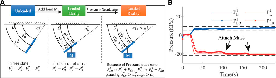
FIGURE 4. The pressure deadzone results in increased bending angle and modeled value in loaded situation.
Only when the pressure change is out of the pressure deadzone will the pressure controller take action, but it will do so only to regulate the pressure to one boundary of the deadzone.
In either case, a repelling pressure change is observed, which would result in two consequences. First, the actual change of α due to external loads would be smaller than the ideal change when pressures are perfectly regulated. This is because of the repelling pressure behavior, which provides an opposing bending torque. Second, the modeled α from measured pressures is to increase. This procedure is depicted in the third column in Figures 4A, 5. Due to the pressure deadzone, the measured
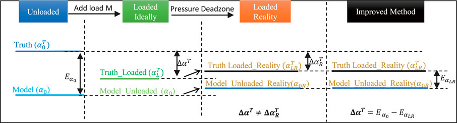
FIGURE 5. Improved Payload Esitmation Method of ExtenSA. The existence of pressure control deadzone would cause the true value
3.3.3 Improved Method by Using Change of Error
The state-change model could be regarded as using the change-of-truth
The modified method reduces the influence of deadzone by using the change of the error between the truth and the modeled unloaded value, instead of
We define the result of
4 Experiments
In this section, the experimental results of the model-based control, external load estimation, and improved version are demonstrated. A dedicated embedded pneumatic control platform was built for these experiments. The control board is a STM32F767ZI NUCLEO board from STMicroelectronics with a core frequency of 216 MHz. It could generate 12-channel individual PWM to control 12 solenoid valves SX12F-DG that could operate at a maximum of 350 Hz. Two pumps are used as sources of pressurized air and vacuum. The overall embedded pneumatic control platform could regulate the pressure from range
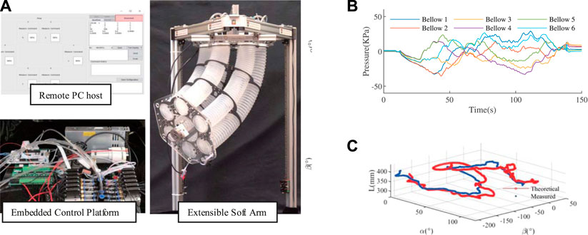
FIGURE 6. (A) The experimental platform set-up consists of a remote PC host to display and give commands, an embedded pneumatic control platform to regulate 12-channel pressure and the soft arm equipped with an IMU, a length sensor, and a force sensor. (B) The optimization generated commands.(C) The simultaneous control of α, β, and L based on the model.
4.1 Model-Based Control
In this section, we show that the model could be used to op-loop control the soft arm by providing the feedback part.
A joystick was used as the command input device, which gives commands to the soft arm to elongate, bend, and rotate. These commands of the configuration space are used to get pressure commands by Eq. 8. The generated pressure commands are shown in Figure 6B. The soft arm tracks these desired
The result is shown in Figure 6C. The pure open-loop control has achieved a moderate tracking performance. This would help to control soft arms to maintain high active compliance by allowing for smaller feedback gains.
4.2 Estimation Result Using State-Change Model
The first experiment is based on tracking sinusoidal signals of bending angle as shown in Figure 7A. Since this is not a static situation, we need to use the moving mean instead. The moving mean of
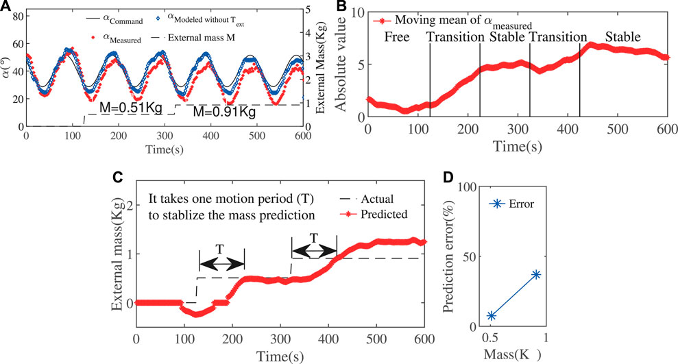
FIGURE 7. (A) Sinusoidal movement of the bending angle with increasing loads. (B)The moving mean of the bending angle
The result of external loads approximation was shown in Figure 7C. The result was capable of being stabilized after one motion period, which is just the time for the stabilization of the mean of
4.3 Estimation Result with Improved Methods
In this section, we use the improved method to estimate the external load and compare it with the result from the state-change model.
In the following experiments, the ExtenSA was set to a constant bending angle of
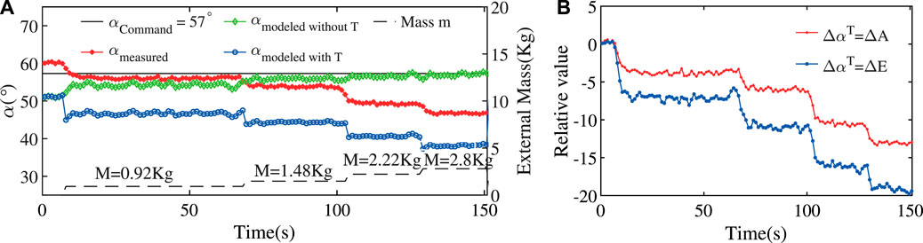
FIGURE 8. Loading Test at Constant Position of ExtenSA. (A) The α change during a loading test where the initial command was given at
In the beginning, the measured angle
After the first loading of a mass of
The comparison between
The estimation result using the
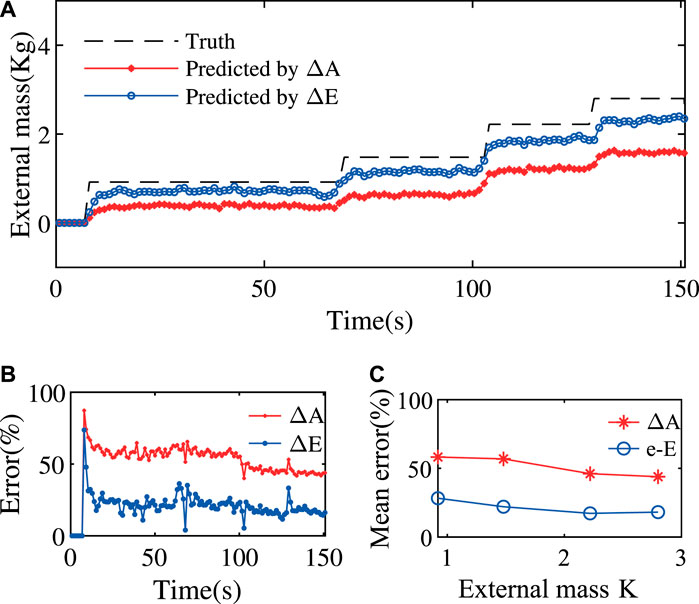
FIGURE 9. Improved Payload Estimation Results of ExtenSA. (A) The payload estimation method using
The estimation errors was plotted in Figures 9B,C. As seen, the overall estimation error is undergoing a slowly reducing process as the external mass is increasing. The estimation error was reduced from around
4.4 Discussion
The state-change model uses the change of bending angle
The improved method uses the change of error
5 Conclusion
In this paper, the possibility and effectiveness of using a simplified analytical model to retrieve external load information are studied. The main idea is to use the state-change model to eliminate the common errors of the modeling part and improve the estimation accuracy by considering practical pressure control deadzones. The promising aspect of utilizing this kind of method is in situations where only limited sensor information is provided or could be economically got. As the soft robotics lack proper sensors and rely on their intrinsic compliance to deal with uncertainty, our state-model-based method, which tries to extract information from this masked behavior, would provide economic guidance for high-level planning.
Data Availability Statement
The raw data supporting the conclusions of this article will be made available by the authors, without undue reservation.
Author Contributions
XC brought up all the estimation methods and conducted all the experiments in this paper. DD took part in the design and fabrication of the soft arm. ZW provided the guidance and funding for the project.
Funding
This work was jointly supported by NSFC Grant 51975268, Hong Kong ITF Grant ITS/457/17FP, ITS/305/19FP, SUSTECH-AISONO Joint Lab Grant, and SUSTECH Edcucation Endowment.
Conflict of Interest
The authors declare that the research was conducted in the absence of any commercial or financial relationships that could be construed as a potential conflict of interest.
Acknowledgments
We would like to thank the Innovation and Technology Fund in Hong Kong for the support of conducting this research.
References
Bajo, A., Goldman, R. E., and Simaan, N. (2011). “Configuration and joint feedback for enhanced performance of multi-segment continuum robots,” in Proceedings-IEEE international conference on robotics and automation, Shanghai, China, May 9–13, 2011 (New York, NY: IEEE), 2905–2912. doi:10.1109/ICRA.2011.5980005
Chen, X., Guo, Y., Duanmu, D., Zhou, J., Zhang, W., and Wang, Z. (2019). Design and modeling of an extensible soft robotic arm. IEEE Robot. Autom. Lett. 4, 4208–4215. doi:10.1109/LRA.2019.2929994
Chen, X., Peng, J., Zhou, J, Chen, Y., Wang, M. Y., and Wang, Z. (2017). “A robotic manipulator design with novel soft actuators,” in IEEE international conference on robotics and automation (ICRA), Singapore, May 29, 2017 (New York, NY: IEEE). doi:10.1109/ICRA.2017.7989220
Chen, X., Yi, J., Li, J., Zhou, J., and Wang, Z. (2018). Soft-Actuator-based robotic joint for safe and forceful interaction with controllable impact response. IEEE Robot. Autom. Lett. 3, 3505–3512. doi:10.1109/LRA.2018.2854409
Della Santina, C., Katzschmann, R. K., Bicchi, A., and Rus, D. (2020). Model-based dynamic feedback control of a planar soft robot: trajectory tracking and interaction with the environment. Int. J. Robot Res. 39, 490–513. doi:10.1177/0278364919897292
Falkenhahn, V., Hildebrandt, A., Neumann, R., and Sawodny, O. (2017). Dynamic control of the bionic handling assistant. IEEE ASME Trans. Mechatron. 22, 6–17. doi:10.1109/TMECH.2016.2605820
Falkenhahn, V., Mahl, T., Hildebrandt, A., Neumann, R., and Sawodny, O. (2015). Dynamic modeling of bellows-actuated continuum robots using the euler-Lagrange formalism. IEEE Trans. Robot. 31, 1483–1496. doi:10.1109/TRO.2015.2496826
Fang, G., Wang, X., Wang, K., Lee, K. H., Ho, J. D., Fu, H. C., et al. (2019). Vision-based online learning kinematic control for soft robots using local Gaussian process regression. IEEE Robot. Autom. Lett. 4, 1194–1201. doi:10.1109/LRA.2019.2893691
Jones, B. A., and Walker, I. D. (2006). Kinematics for multisection continuum robots. IEEE Trans. Robot. 22, 43–55. doi:10.1109/TRO.2005.861458
Katzschmann, R. K., Santina, C. D., Toshimitsu, Y., Bicchi, A., and Rus, D. (2019). Dynamic motion control of multi-segment soft robots using piecewise constant curvature matched with an augmented rigid body model. 2019 2nd IEEE international conference on soft robotics (robosoft), Seoul, Korea, April 14–18, 2019 (New York, NY: IEEE), 454–461. doi:10.1109/ROBOSOFT.2019.8722799
Kim, S., Laschi, C., and Trimmer, B. (2013). Soft robotics: a bioinspired evolution in robotics. Trends Biotechnol. 31, 287–294. doi:10.1016/j.tibtech.2013.03.002
Laschi, C., and Cianchetti, M. (2014). Soft robotics: new perspectives for robot bodyware and control. Front. Bioeng. Biotechnol. 2, 3. doi:10.3389/fbioe.2014.00003
Laschi, C., Mazzolai, B., and Cianchetti, M. (2016). Soft robotics: technologies and systems pushing the boundaries of robot abilities. Sci. Robot. 1, eaah3690. doi:10.1126/scirobotics.aah3690
Majidi, C. (2013). Soft robotics: a perspective-current trends and prospects for the future. Soft Robot. 1, 5–11. doi:10.1089/soro.2013.0001
Malzahn, J., and Bertram, T. (2014). Collision detection and reaction for a multi-elastic-link robot arm. IFAC Proceedings Volumes 47, 320–325. doi:10.3182/20140824-6-za-1003.01545
Marchese, A. D., Onal, C. D., and Rus, D. (2014). Autonomous soft robotic fish capable of escape maneuvers using fluidic elastomer actuators. Soft Robot. 1, 75–87. doi:10.1089/soro.2013.0009
Mohd Jani, J., Leary, M., Subic, A., and Gibson, M. A. (2014). A review of shape memory alloy research, applications and opportunities. Mater. Des. 56, 1078–1113. doi:10.1016/j.matdes.2013.11.084
Mosadegh, B., Polygerinos, P., Keplinger, C., Wennstedt, S., Shepherd, R. F., Gupta, U., et al. (2014). Pneumatic networks for soft robotics that actuate rapidly. Adv. Funct. Mater. 24, 2163–2170. doi:10.1002/adfm.201303288
O’Halloran, A., O’Malley, F., and McHugh, P. (2008). A review on dielectric elastomer actuators, technology, applications, and challenges. J. Appl. Phys. 104, 071101. doi:10.1063/1.2981642
Polygerinos, P., Lyne, S., Wang, Z., Fernando, L., Mosadegh, B., Whitesides, G. M., et al. (2013). Towards a soft pneumatic glove for hand rehabilitation. 2013 IEEE/RSJ International Conference on Intelligent Robots and Systems, Tokyo, Japan, November 3–7, 2013 (New York, NY: IEEE), 1512–1517
Polygerinos, P., Wang, Z., Galloway, K. C., Wood, R. J., and Walsh, C. J. (2015a). Soft robotic glove for combined assistance and at-home rehabilitation. Robot. Autonom. Syst. 73, 135–143. doi:10.1016/j.robot.2014.08.014
Polygerinos, P., Wang, Z., Overvelde, J. T., Galloway, K. C., Wood, R. J., Bertoldi, K., et al. (2015b). Modeling of soft fiber-reinforced bending actuators. IEEE Trans. Robot. 31, 778–789. doi:10.1109/TRO.2015.2428504
Pratt, G. A., and Williamson, M. M. (1995). Series elastic actuators. IEEE Inter. Conf. Intel. Robot. Sys. 1, 399–406. doi:10.1109/iros.1995.525827
Santina, C. D., Bicchi, A., and Rus, D. (2019). Dynamic control of soft robots with internal constraints in the presence of obstacles. IEEE international conference on intelligent robots and systems, Macau, China, November 3–8, 2019 (New York, NY: IEEE), 6622–6629. doi:10.1109/IROS40897.2019.8967668
Suarez, A., Heredia, G., and Ollero, A. (2018). Physical-virtual impedance control in ultralightweight and compliant dual-arm aerial manipulators. IEEE Robot. Autom. Lett. 3, 2553–2560. doi:10.1109/LRA.2018.2809964
Tondu, B., and Lopez, P. (2000). Modeling and control of McKibben artificial muscle robot actuators. IEEE Contr. Syst. Mag. 20, 15–38. doi:10.1109/37.833638
Wang, C., Frazelle, C. G., Wagner, J. R., and Walker, I. (2020). Dynamic control of multi-section three-dimensional continuum manipulators based on virtual discrete-jointed robot models. IEEE ASME Trans. Mechatron. 4435, 1. doi:10.1109/TMECH.2020.2999847
Wang, L., and Wang, Z. (2020). Mechanoreception for soft robots via intuitive body cues. Soft Robot. 7, 198–217. doi:10.1089/soro.2018.0135
Wang, Z., Polygerinos, P., Overvelde, J. T. B., Galloway, K. C., Bertoldi, K., and Walsh, C. J. (2017). Interaction forces of soft fiber reinforced bending actuators. IEEE ASME Trans. Mechatron. 22, 717–727. doi:10.1109/TMECH.2016.2638468
Webster, R. J., and Jones, B. A. (2010). Design and kinematic modeling of constant curvature continuum robots: a review. Int. J. Robot Res. 29, 1661–1683. doi:10.1177/0278364910368147
Yi, J., Chen, X., Song, C., and Wang, Z. (2018). Fiber-reinforced origamic robotic actuator. Soft Robot. 5, 81–92. doi:10.1089/soro.2016.0079
Yi, J., Chen, X., and Wang, Z. (2018). A three-dimensional-printed soft robotic glove with enhanced ergonomics and force capability. IEEE Robot. Autom. Lett. 3, 242–248. doi:10.1109/LRA.2017.2737481
Zhou, J., Chen, Y., Chen, X., Wang, Z., Li, Y., and Liu, Y. (2020). A proprioceptive bellows (PB) actuator with position feedback and force estimation. IEEE Robot. Autom. Lett. 5, 1867–1874. doi:10.1109/LRA.2020.2969920
Zhou, J., Chen, X., Chang, U., Lu, J.-T., Leung, C. C. Y., Chen, Y., et al. (2019). A soft-robotic approach to anthropomorphic robotic hand dexterity. IEEE Access 7, 101483–101495. doi:10.1109/ACCESS.2019.2929690
Keywords: modeling, control, soft robot application, soft robot, soft arm
Citation: Chen X, Duanmu D and Wang Z (2021) Model-Based Control and External Load Estimation of an Extensible Soft Robotic Arm. Front. Robot. AI 7:586490. doi: 10.3389/frobt.2020.586490
Received: 23 July 2020; Accepted: 14 December 2020;
Published: 29 January 2021.
Edited by:
Concepción A. Monje, Universidad Carlos III de Madrid, SpainReviewed by:
Alejandro Suarez, Sevilla University, SpainLuis Fernando Nagua, Universidad Carlos III de Madrid, Spain
Copyright © 2021 Chen, Duanmu and Wang. This is an open-access article distributed under the terms of the Creative Commons Attribution License (CC BY). The use, distribution or reproduction in other forums is permitted, provided the original author(s) and the copyright owner(s) are credited and that the original publication in this journal is cited, in accordance with accepted academic practice. No use, distribution or reproduction is permitted which does not comply with these terms.
*Correspondence: Zheng Wang, emhlbmcud2FuZ0BpZWVlLm9yZw==