 Julian Neu1,2*
 Jonas Hubertus3Sipontina Croce1,2Günter Schultes3Stefan Seelecke1,2
 Gianluca Rizzello1,2
- 1Department of Systems Engineering, Saarland University, Saarbrücken, Germany
- 2Department of Material Science, Saarland University, Saarbrücken, Germany
- 3Department of Sensors and Thin Films, University of Applied Sciences of Saarland, Saarbrücken, Germany
The availability of compliant actuators is essential for the development of soft robotic systems. Dielectric elastomers (DEs) represent a class of smart actuators which has gained a significant popularity in soft robotics, due to their unique mix of large deformation (>100%), lightweight, fast response, and low cost. A DE consists of a thin elastomer membrane coated with flexible electrodes on both sides. When a high voltage is applied to the electrodes, the membrane undergoes a controllable mechanical deformation. In order to produce a significant actuation stroke, a DE membrane must be coupled with a mechanical biasing system. Commonly used spring-like bias elements, however, are generally made of rigid materials such as steel, and thus they do not meet the compliance requirements of soft robotic applications. To overcome this issue, in this paper we propose a novel type of compliant mechanism as biasing elements for DE actuators, namely a three-dimensional polymeric dome. When properly designed, such types of mechanisms exhibit a region of negative stiffness in their force-displacement behavior. This feature, in combination with the intrinsic softness of the polymeric material, ensures large actuation strokes as well as compliance compatibility with soft robots. After presenting the novel biasing concept, the overall soft actuator design, manufacturing, and assembly are discussed. Finally, experimental characterization is conducted, and the suitability for soft robotic applications is assessed.
1 Introduction
Dielectric Elastomers (DEs) are a type of electro-mechanical transducers which react to an electric voltage with a significant change in shape. A typical DE consists of a thin polymeric membrane, whose thickness ranges from few tens to a few hundreds of micrometers, coated with compliant electrodes on both sides. Commonly used materials for the elastomer are acrylics and silicone (Chiba, 2014), while the electrodes can be fabricated with a mixture of carbon powder and silicone oil (Kornbluh et al., 2004) as well as stretchable metallic thin films (Hubertus et al., 2020). When a high voltage on the order of several kV is applied to the electrodes, charges of opposite signs are stored onto them. These charges induce electrostatic forces which let the electrodes attract each other. Such an effect leads to a thinning of the membrane which, in turn, is followed up by an area expansion, as a result of the incompressibility of the silicone (Pelrine et al., 2001b).
The principle described above makes DEs a promising technology for electrically-controllable actuators. Features such as large strain (over 100%), as well as high energy efficiency and density (Kornbluh et al., 2004), enabled the development of DE-based mechatronic devices which are capable of performance not achievable with competing technologies (Pelrine et al., 2001a; York et al., 2013). The possibility of structuring the compliant electrodes in various ways, together with the material overall flexibility, has led researchers to develop a wide spectrum of DE actuator (DEA) solutions. Some authors demonstrated how DEAs can be used to manufacture lightweight fluid pumps (Mohd Ghazali et al., 2017; Cao et al., 2019; Linnebach et al., 2020), or showcased the possibility of generating high forces (Hau et al., 2018b). Further examples of DEA prototypes range from DE driven loudspeakers (Rustighi et al., 2018), contactors (Linnebach et al., 2019), and valves (Hill et al., 2017) to jumping devices (Luo et al., 2020) and medical systems (Goulbourne et al., 2003), to mention a few.
Due to their intrinsically high compliance, DEs have also been extensively used as actuators for soft robots. Soft robotics is a current research topic that deals with the investigation and development of highly flexible robots, by emulating bio-inspired actuation concepts (Albu-Schaffer et al., 2008). The high flexibility and compliance which characterize soft robots ensure a safer interaction with humans, as well as the possibility to achieve complex deformation patterns. Examples in this field range from bending arm-like structures (Xing et al., 2020) to crawling or rolling DE based-robots (Duduta et al., 2017; Henke et al., 2017; Li et al., 2018), as well as swimming jellyfish robots (Godaba et al., 2016). It can be noted, however, that many of the above mentioned actuators exploit a locomotion mode to generate a sufficient movement of the device. Despite being suitable for certain target applications or goals, locomotion does not fully exploit the high strain potential of the material.
To properly design soft DEA solutions which enable full exploitation of the material large stroke capability, more advanced design solutions must be considered. Hodgins et al. (2011) showed that, by coupling a DE membrane with an appropriate mechanical biasing system (e.g., a mass, a spring), the resulting stroke of the actuator can be remarkably increased. This concept has been extensively exploited in conventional DEA systems (Wang et al., 2009; Berselli et al., 2010; Lu et al., 2016), as well as in some DEA-driven soft robots (Zhang et al., 2006; Kofod et al., 2007). A further comparative study conducted in Hodgins et al. (2013) revealed that, if the DE biasing mechanisms exhibits a region with negative slope (i.e., stiffness) within its force-displacement characteristics, it allows to achieve a drastically higher stroke and work output compared to conventional mass- and linear spring-type bias mechanisms. Such negative-rate biasing spring (NBS) element can be practically manufactured in many ways, e.g., via a pre-compressed steel buckled beam (Hodgins and Seelecke, 2010), attracting permanent magnets (Loew et al., 2018), or more advanced types of mechanisms (Berselli et al., 2011). NBS elements have been extensively used to improve the performance of simple DEA configurations, e.g., single degree-of-freedom industrial actuators (Berselli et al., 2011; Hau et al., 2018b; Linnebach et al., 2019). The biasing systems used in most of the current DE soft robots, however, lack the above mentioned NBS principle, thus they do not allow to exploit the high flexibility of the DE to generate soft actuators with large stroke. This is possibly due to the rigid materials commonly used to manufacture the NBS itself, which are mostly based on metal, as well as due to the stiff frames and housings required to implement mechanical clamping and connections. Both, metal based-NBS elements and rigid clamping components represent then additional stiff parts, whose characteristics are not compatible with the compliance requirements of soft robotics. Due to these reasons, the development of large-stroke soft DEA components, which effectively integrate the benefits of NBS elements while keeping at the same time an overall compliant structure, is still an unexplored field.
To overcome the above mentioned issue, and thus enable large-stroke DE soft actuators for robotic and wearable applications, a compliant and flexible NBS element is needed, which does not require using additional rigid components. In this paper, we propose a novel type of NBS biasing element for DEAs, based on three-dimensional domes manufactured out of soft polymeric material (Young’s modulus on the order of a few tens of kPa). Earlier research works have already demonstrated that, by properly designing the geometry of such domes, a region of negative stiffness can be induced in their force-displacement characteristics (Madhukar et al., 2014; Alturki and Burgueño, 2019). In this way, a soft and fully polymer-based NBS is achieved. Due to the compliance matching between DE and dome materials, this solution permits in principle to achieve a fully soft and large-stroke actuator system. Those types of mechanisms, however, have not been previously adopted as biasing elements for DE membranes, to the best of our knowledge. The present manuscript represents then the first systematic investigation of soft biasing system concepts for high-stroke DEAs, which leads to potential applications in soft robotics as well as wearables.
After presenting the dome concept, its design and manufacturing process will be discussed. Based on experimental characterization of both DE and biasing element, a heuristic approach is then proposed for finding the dome design which maximizes the overall DEA stroke. The optimized DEA is then assembled and characterized experimentally via an extensive set of experiments, aimed at evaluating its static and dynamic performance, as well as its ability to operate while being stretched and deformed. The ability of the dome-DEA system to perform a stroke under a deformation/stretching state opens up the perspective to manufacture completely flexible micro-arrays of DEAs. This novel technology could be potentially used to develop soft and flexible smart skins for soft robots, as well as wearable surfaces, that exhibit not only cooperative actuation capabilities but can also sense contact forces and distributed displacements. Despite flexible DEA arrays have already been presented in recent research (Marette et al., 2017), the lack of a soft NBS-type biasing system does not allow to truly exploit the high-stroke potential of the DE material.
We also point out that this paper is an extended version of the work previously presented in Neu et al. (2020). In our previous research, a first DEA prototype based on a silicone dome was presented. In here, we extend the results in Neu et al. (2020) by including:
• a detailed description of the dome manufacturing process;
• a systematic approach to optimize the design of the dome geometry for a specific target application;
• an improved actuator design solution which ensures safer operations regarding the high-voltage;
• an extensive experimental campaign aimed at characterizing the novel dome-DEA system in terms of stroke, dynamic performance, and energy consumption;
• an investigation of the actuator performance while operating in a deformed state.
The structure of the article is organized as follows. After explaining the operating principle of a DEA in Section2, the novel dome-based biasing system is described in Section 3. An optimization procedure for the dome design is presented in Section 4. Manufacturing and performance characterization of the full actuator system are then shown in Section 5. Finally, concluding remarks are discussed in Section 6.
2 Dielectric Elastomer Actuators
In this section, the operating principle of DE membranes will be presented first. Then, the role of the biasing system in determining the performance of a DEA is discussed in details.
2.1 Basics of Dielectric Elastomers
As described in Section 1, a typical DE consists of a polymer film coated with compliant electrodes on both sides. When a voltage is applied to such a DE, charges of opposite signs are stored in the electrodes. These charges lead to attractive electrostatic forces which cause a thinning of the dielectric film and, due to the incompressibility of the elastomer, an expansion of the membrane area, as shown in Figure 1. The electrically-induced stress on the silicone film
with
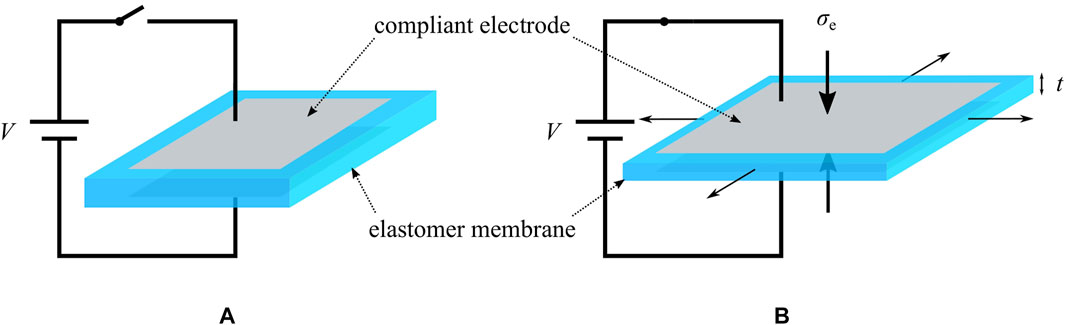
FIGURE 1. Basic principle of a dielectric elastomer. (A) The membrane is initially undeformed. (B) When a high voltage is applied to the compliant electrodes, the silicone membrane gets thinner and expands in area.
While commercially available materials are generally used for the polymeric film [e.g,. 3M VHB 4910 acrylics as in Frediani et al. (2014), or Wacker Elastosil silicone as in Matysek et al. (2008)], the electrodes can be manufactured in several possible ways (Rosset and Shea, 2013). For instance, it is possible to apply a mixture of silicone oil and carbon black by hand (Lu et al., 2016) or, to achieve a more uniform electrode layer, via screen-printing (Fasolt et al., 2017). A rather new approach, which has been proposed in Hubertus et al. (2020), is based on sputtering a metallic thin film (thickness of 10 nm) onto a pre-stretched silicone membrane. After releasing the pre-stretch, the metallic film forms wrinkles without delamination, and can be deformed even above the level of pre-stretch without losing conductivity. This new type of metallic DE electrode is used in the prototype presented in this manuscript, to showcase its suitability for soft DEAs. Even though the use of metallic electrodes may appear contradictory for the scope of soft robotics, the 10 nm thick sputtered metallic thin film has practically no influence on the stiffness of the DE. In addition, according to Hubertus et al. (2020), the metal electrodes exhibit a sheet resistance which is about two orders of magnitude smaller than the one of usual carbon black electrodes, thus allowing to improve the actuation speed as well as the energy efficiency.
2.2 Basics of Dielectric Elastomer Actuators
Due to the high flexibility of DE material, the actuation principle described above can be adapted to several geometries and configurations. In this work, we focus on a specific class of DEA systems, namely a circular out-of-plane DEA (COP-DEA). An example of COP-DEA layout is shown in Figure 2A. The grey part corresponds to the compliant electrodes, while the blue elements represent the passive membrane. The geometry of a COP-DEA is generally defined by the outer and inner radii, denoted as
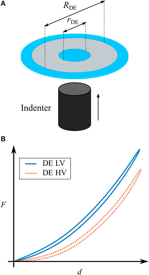
FIGURE 2. (A) Schematic depiction of a COP-DEA, active electrode-covered material (depicted in gray) and passive elastomer material (depicted in blue). (B) Qualitative sketch of the two characterizing curves of a COP-DEA. The blue continuous line represents the low voltage curve and the dotted red line represents the high voltage curve.
For characterizing a COP-DEA, the center passive part (i.e., the inner blue circle in Figure 2A) has to be mechanically deflected out-of-plane, while its reaction force is measured at the same time, as shown in Figure 2A. We denote as d and F the corresponding out-of-plane displacement and reaction force, respectively. This can be done with and without a voltage applied to the electrodes, thus leading to a pair of force-displacement curves describing the operating range of the actuator. A qualitative example of such characterization curves is reported in Figure 2B. In here, the continuous blue line represents the DE with no or a very low voltage (LV) applied, while the dotted red line describes the case with applied high voltage (HV). The curves basically show that the thinning of the membrane due to the HV-induced activation leads to a softening of the DE. Note also that the curves exhibit a moderate hysteresis under cyclic operations, which is due to the viscoelastic behavior of the elastomer.
In order to exploit the softening effect in Figure 2B for actuation purposes, a mechanical preload must be applied to the membrane. In case of the COP-DEA, such a preload can be obtained by connecting a passive spring element to the center passive part of the membrane. Hodgins et al. (2013) compared different types of biasing elements in terms of resulting maximum stroke. Based on such analysis, it is shown that a NBS has the highest potential for the generation of high strokes, compared to more conventional masses and linear springs.
To clarify why a NBS outperforms other types of preloading mechanisms, the relationship between biasing mechanism and DEA performance must be properly understood. To this end, it is convenient to study the force-displacement characteristics of the different biasing elements in combination with the curves of the DE, namely a positive-rate biasing spring (PBS) and an example of NBS, both reported in Figure 3. In particular, Figure 3A shows the force-displacement curves of both biasing systems, together with their schematic depiction. The dashed yellow line describes the NBS. In here, the region confined between the two local extrema exhibits a negative slope, which can be characterized by a stiffness parameter
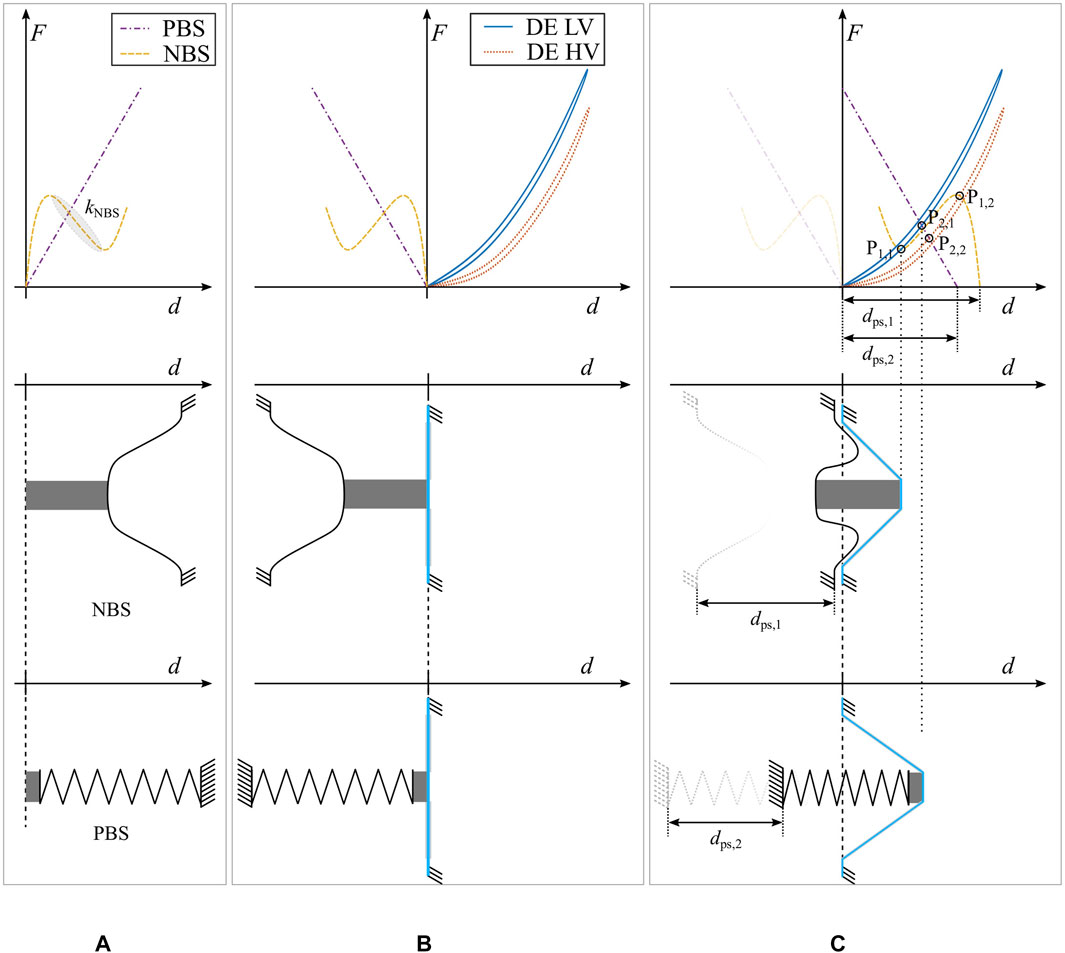
FIGURE 3. Schematic depiction of the biased DEA. (A) shows the force-displacement curves of a PBS and a NBS in the first row. In the lower part, a sketch of the two considered biasing elements is depicted. (B) shows the resulting system curves and a sketch of the assembly, when a COP-DEA is brought into contact with the biasing elements. (C) represents the system force-displacement curves in the biased state, and shows the resulting configuration in each one of the two sketched assemblies.
For assembling a COP-DEA, the biasing element has to be connected to the center passive part of the elastomer membrane. As soon as a contact is established between both parts, with no forces exchanged among them, the resulting system configuration can be described by the diagram in Figure 3B. In here, the grey part represents a spacer, which serves as mechanical connection element. In this assembly, the DE and the biasing elements are working against each other: a deflection of the DE center part in the direction of positive d values corresponds to a pulling on the biasing springs, which is why the spring curves are mirrored with respect to the y-axis. Note how the application of a HV in this state would not result in a movement of the center part, since no force is being exchanged between DE and biasing element.
In order to generate a stroke the DE membrane and the bias element have to be moved relatively closer to each other, by an amount of
By comparing the two biasing solutions in Figure 3C, it is now evident that the intersection points of the NBS curve exhibit a much wider separation than the ones of the PBS case. Since the distance between the intersections coincides with the actuator stroke, it can be concluded that a NBS leads to a better performing DEA, compared to a PBS. Note how the key aspect of the NBS is represented by the region of inverted slope
3 Novel Dome-Based Biasing System
This section presents the novel biasing solution based on the polymeric dome. After discussing the main idea, a new dome design layout is presented and experimentally characterized.
3.1 Basic Concept
In DE applications, conventional NBS elements usually consist of thin, pre-compressed metal beams (Hau et al., 2018a). By compressing a beam with an initial length
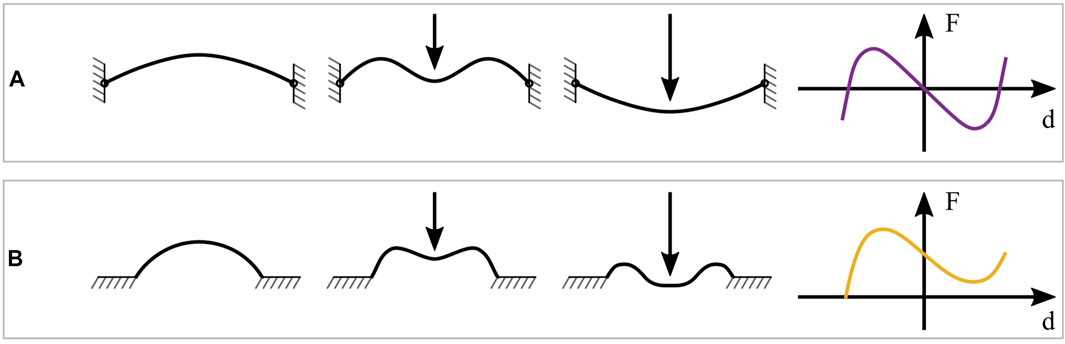
FIGURE 4. Different realizations of bi-stable mechanisms. (A) pre-compressed buckled beam, snapping behavior under a load and corresponding force-displacement curve. (B) polymeric dome, snapping behavior under a load and corresponding force-displacement curve.
Buckled beams which follow this behavior usually exhibit a point-symmetrical force-displacement curve with respect to the unstable equilibrium point, i.e.,
The idea of using polymeric domes as negative-stiffness mechanisms, instead of buckled beams, is based on results presented in earlier research works (Madhukar et al., 2014; Alturki and Burgueño, 2019). The use of cast silicone domes allows to combine the stress-free manufacturing together with the softness and flexibility that are required by the biasing system. An example of such a dome, together with its corresponding force-displacement curve, is shown in Figure 4B. In contrast to the force-displacement curve of the buckled beam, the dome characteristic does not show an unstable equilibrium position in the center of the negative branch. Since the curve does not lie below the horizontal line corresponding to
3.2 Dome Layout
To develop a dome-based NBS concept which is suitable for DE applications, the basic layout presented in Madhukar et al. (2014) is considered as a starting design point. To make such a geometry compatible with the COP-DEA described in Section 2.2, the design in Madhukar et al. (2014) is properly modified by surrounding the isolated dome with a relatively thick base, as well as by adding a round flat-top. A cross-sectional sketch of the modified dome design is reported in Figure 5A. The base serves as a pseudo-solid frame for the dome, while the flat-top is used for shaping its force-displacement characteristic curve. More specifically, increasing the flat-top radius r leads to a shorter length of the thin walled region, which results in a higher compression stress given the same deflection of the center part. A larger compression stress is expected to increase the maximum force in the force-displacement curve. Other relevant geometric parameters are the wall thickness t, the height of the dome H, and the base radius R. In order to match the diameter of the sputtered DE, given by
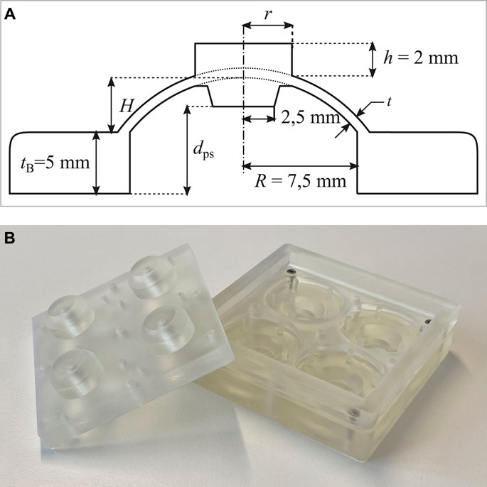
FIGURE 5. (A) Cross-sectional sketch of the dome geometry, with all the relevant parameters. Note how r, t, and H are left free to design. (B) Picture of a partly assembled 3D printed mold.
3.3 Dome Manufacturing
For manufacturing the domes, a casting process based on a pourable addition-curing silicone rubber that vulcanizes at room temperature [SilGel® 612 EH, mixing ratio 1.5:1 (A:B)] is used. The casting molds consist of three solid parts, which are created with a 3D SLA printer. These parts are printed with a minimum layer height of 25 μm, which also coincides with the value of the printer XY resolution, as specified by the manufacturer. Figure 5B shows a picture of a partly assembled mold. For achieving more comparable results with one casting process, one mold can be used to manufacture four individual dome geometries, which can either be identical to account for manufacturing tolerances, or can possibly differ in one or more parameters.
The manufacturing process consists of the following steps:
1. The silicone is catalyzed with a mixing ratio of 1.5:1 (A:B);
2. The catalyzed silicone is cast into the bottom part of the mold;
3. The mixture is degassed in a vacuum chamber for 5 min;
4. The top part of the mold is inserted;
5. The screws are tightened with a torque wrench.
After completing the above steps, the silicone is cured at room temperature for at least 2 h before the domes are released from the mold, and then it is post-cured for two more hours at 180°C. The purpose of the thermal curing is to ensure an optimal vulcanization of the silicone, which reduces the hysteresis in its response.
3.4 Dome Characterization
The characterization process aims at evaluating the dome force-displacement characteristic curve. To this end, an indenter connected to a linear motor (Aerotech, Inc., Model: ANT-25LA) is used to apply a
The biggest influences on the manufacturing accuracy of the dome are expected to arise from the 3D printing process of the mold, as well as from the manual mixing of the silicone. To account for such inaccuracies, a total of eight batches are manufactured from three different molds having the same geometry. In this way, the effect of manufacturing tolerances on the reproducibility of the dome force-displacement curves can be properly quantified via repeated experiments.
Figure 6 shows the results of the characterization of four different dome geometries. All of them share the same values of
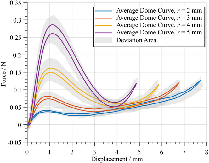
FIGURE 6. Average force-displacement curves of four different dome geometries. A total of eight batches were manufactured with three different molds, having the same geometry. Each solid curve is computed based on the average behavior between eight specimen, which all share the same nominal geometry. The gray area shows the maximum and minimum deviation of the measured specimen.
4 Dome Design Optimization
In this section, an application-specific dome design procedure is discussed. First, a target DE geometry is chosen, and its force-displacement curves are characterized at different voltage values. Then, a method is presented to optimize the free parameters of the dome, in such a way to match the given DE curves. In this way, a large stroke dome-DEA system can be effectively achieved.
4.1 Dielectric Elastomer Characterization
The first steps toward the development of a large-stroke soft DEA consist in the selection and characterization of a target DE geometry. As mentioned in Section 2.2, COP-DEAs with sputtered thin metallic electrodes (thickness of 10 nm) are chosen in this work. The material used for the elastomer membrane is a Wacker ELASTOSIL® film 2030, with an initial thickness of
The starting point for the actuator design consists of the evaluation of the DE characterization curves. To perform such a characterization, the sputtered DE is glued to a silicone ring having the same inner diameter
The characterization experiment described above is repeated multiple times, by considering 4 DE membrane elements, in such a way to generate average curves for both high- and low-voltage cases. The results of the characterization process are shown in Figure 7. A residual hysteresis is observed, which is due to the intrinsically irreversible nature of the DE. The gray areas show the range of deviation among all the experiments, which depend on both manufacturing and assembling tolerances as well as on the repeatability of the measurement. These average curves can then be used to determine the ideal characteristics of an optimal biasing system, which ideally lies in the middle of the gap between the two DE curves. The characteristic of an ideal biasing system is reported as a dashed black line in Figure 7 (see Section 2.2 for details). Such a line is obtained by selecting two points corresponding to
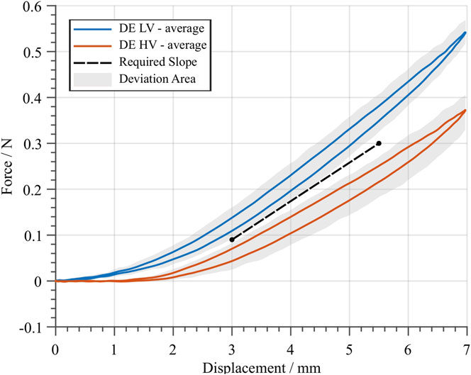
FIGURE 7. Average DE curves for the low- (blue) and high- (red) voltage case, based on the average between four different specimens. A sine-wave displacement profile with an amplitude of
4.2 Dome Design Optimization
In order to maximize the DEA system stroke, one must find an optimal dome geometry (in terms of r, t, and H) which matches as close as possible the required slope depicted in Figure 7. To perform an effective design, it is important to find a systematic approach which permits to shape the dome characteristic curves in a desired way. From Figure 6, it is evident that r has a strong influence on the negative slope region of the dome curve. We define
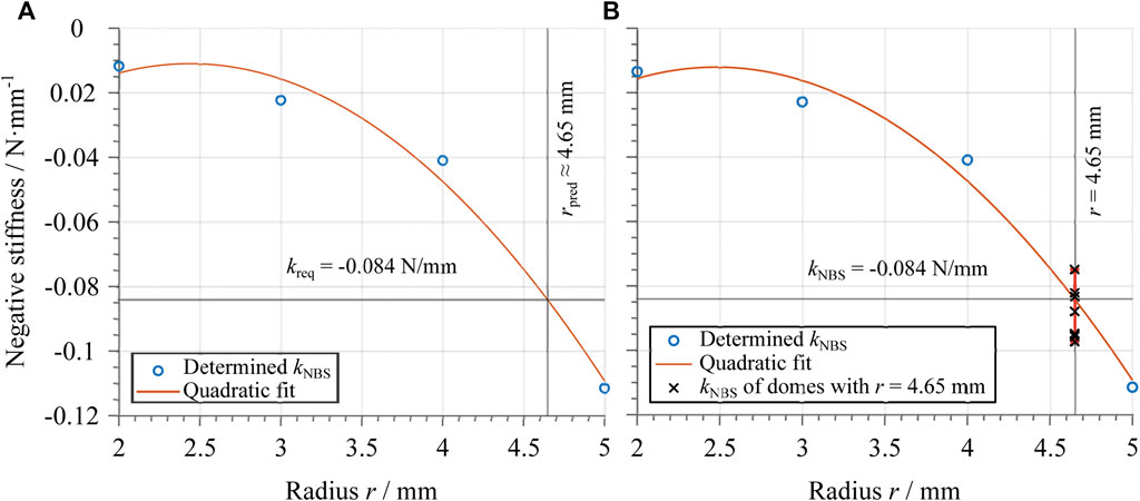
FIGURE 8. (A) Dependency of the negative stiffness of the dome average curves on the flat-top radius. The circles represent the determined values of the negative slope
The approach described above is then applied by considering the required slope value
4.3 Optimal Design Validation
To validate the design in the previous section, various domes with the same optimal geometry (
5 Actuator Manufacturing and Characterization
In this section, manufacturing and assembly of the overall DEA are first discussed. Then, an experimental characterization campaign is conducted to evaluate the full system performance.
5.1 Actuator Assembly and Manufacturing
A rendered view of the whole assembly is shown in Figure 9A. The electrical connections with the metallic DE electrodes are achieved via copper tape, which is attached prior to the actuator assembly. Double-sided tape is cut with a cutting machine, and used for the connections between the center of the DE and the extension of the dome flat-top, as well as for the connection between the dome base and the outer DE part. Note how, in contrast to the very first dome-based DEA prototype presented in Neu et al. (2020), the mechanism in Figure 9A is designed to allow safer operations, since the high voltage controlled DE is placed underneath the isolating dome. Figures 9B,C further show the actuation principle of the considered actuator, by also illustrating the relationship between stroke
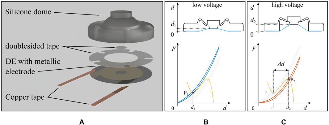
FIGURE 9. (A) Rendered explosion view of the flexible DEA. Sketch of the assembled actuator together with the system force-displacement curves, (B) without voltage and (C) with high voltage applied to the electrodes.
To allow for a more precise assembly in terms of adjustment between dome, tape, and DE, as well as a planar connection, several 3D printed tools are used. In this way a manual placement can be avoided, and thus a more accurate assembly can be achieved. Small channels at the bottom of the dome base ensure air ventilation, in order to prevent pressure changes in the volume between DE and dome during the actuation.
The procedure needed to manufacture the system in Figure 9A is reported in the following, where the results of the most relevant steps are illustrated in Figure 10:
1. A suitable dome design is determined based on the optimization method explained in Section 4, and subsequently manufactured and validated;
2. By means of post-processing implemented in MATLAB, the optimal value of the horizontal shift between dome and DE curves, denoted as
3. Domes with different values of
4. The DE which is used for the actuator is characterized prior to the assembly. Note that only the LV force-displacement curve is measured in this case, because it is not possible to nondestructively measure the DE HV curve, as long as the DE is not glued to the dome. This is done to improve the accuracy, and allows to determine if the curves of the used DE and the manufactured domes match properly;
5. By considering several manufactured domes, all sharing the same optimal design but differing in terms of
6. The overall actuator is assembled according to the method describe above in this Section.
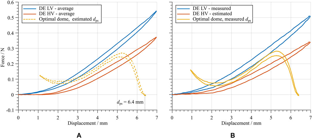
FIGURE 10. (A) Measured force-displacement curve of the dome, whose geometry is determined based on the optimization method in Section 4, together with the average DE curves from Figure 7, in order to check the suitability of the design and to determine the amount of pre-stretch. (B) Measured DE LV curve and estimated DE HV curve, together with a manufactured dome with the optimized geometry and value of
The estimation of an appropriate range for
5.2 Actuator Characterization
In order to characterize the manufactured DEA the stroke and energy consumption is measured for different voltage input signals and in several mechanically deformed configurations. To this end, a laser sensor (Keyence, Model: LK-G87) is used to measure the stroke of the flat-top of the DEA while the voltage signal is applied and an NI LabVIEW module (PXI-7852) is used to monitor an analog voltage output of the voltage amplifier, which corresponds to the current needed to charge and discharge the DE. To assess the validity of the design, the plot generated in step 5 of the manufacturing process in Section 5.1 provides the maximum expected stroke, which is approximately
To properly characterize the DEA performance, different excitation voltage signals are applied to the electrodes. In order to examine the dependency of the actuator stroke on the applied voltage amplitude, a square wave voltage signal is used as first test signal for the DEA. Square wave inputs with a frequency of
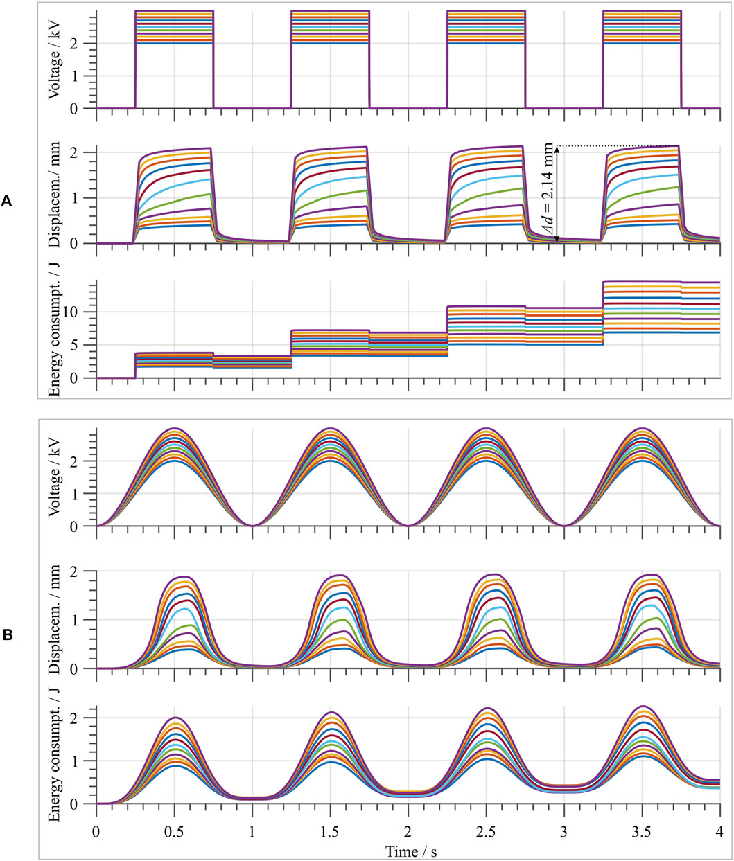
FIGURE 11. (A) upper part, shows the square wave voltage input signals with different amplitudes ranging from 2 to 3 kV in steps of
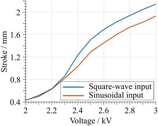
FIGURE 12. Maximum stroke as a function of the applied voltage amplitude. The blue curve represents the values obtained from the square wave input signal, while the red curve is obtained from the sinusoidal input.
The same characterization is then repeated by considering a sinusoidal voltage input, by using the same voltage amplitudes as for the square wave case. The obtained results are shown in Figure 11B. When the maximum measured stroke is compared to the one obtained with the square wave input, given the same voltage value, a slight decrease is observed. This becomes evident in Figure 12, when the blue (square-wave) and red (sine-wave) curves are compared. The decrease can be explained by the creep due to the hysteresis of the material system, which is also observed with the square-wave input. At the same time, the total energy consumption is drastically smaller for the sine-wave input. This is due to the lower frequency content of the input signal, which results in overall smaller dissipation. For this case, an average energy efficiency figure of 90.96% is estimated. Note how this value is significantly higher compared to the previous square wave case.
Additionally, to determine the actuator dynamic range of operation, a sine-sweep input voltage test is conducted. The considered signal has a constant amplitude of 3 kV, while its frequency ranges from 1 to 200 Hz with a linear increment of
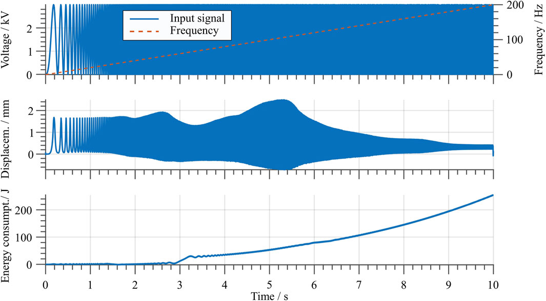
FIGURE 13. Stroke and energy consumption with a sine sweep input signal. The top graph shows the input signal in blue and the frequency over time with a dashed red line.
In Section 1 the idea of using an array of multiple flexible DEAs as a smart, deformable skin was introduced. In order to show the suitability of the developed soft DEA for such kinds of applications, the actuator was also characterized when subject to a state of mechanical deformation. In particular, the DEA is characterized while being deformed according to different curvature values, as if it is attached to various cylinders with different radii. For a first evaluation, four different curvature radii are chosen, i.e., 100, 80, 60 and 40 mm, see Figure 14B. The results are shown in Figure 14A, in terms of both stroke and energy consumption. The amplitude of the square wave excitation signal is
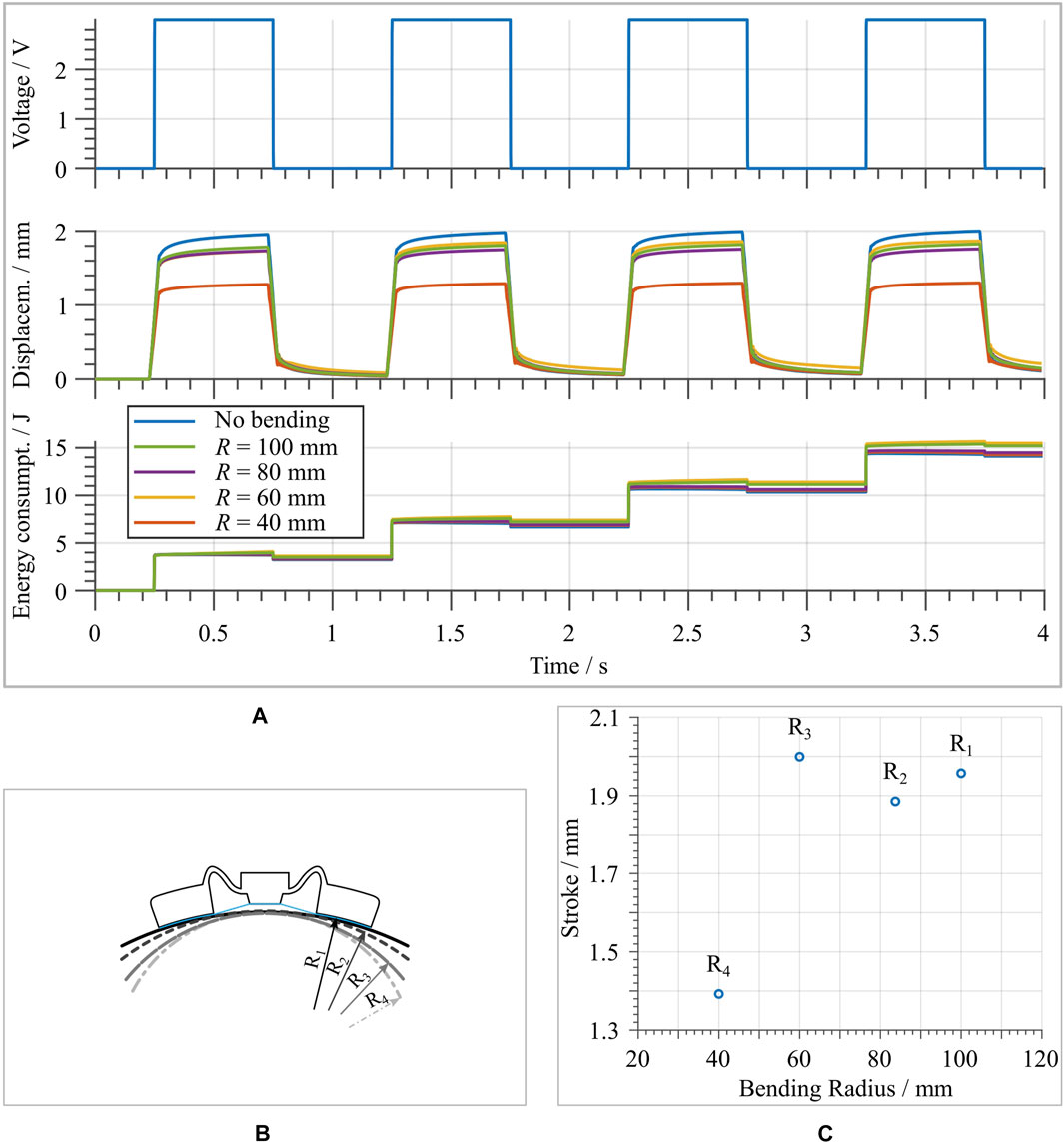
FIGURE 14. (A) Stroke and energy consumption measurement of the actuator in different deformed configurations, together with the results in the undeformed state as reference. (B) Cross-sectional schematic of the applied deformation. Note that the deformation corresponds to a cylindrical, rather than spherical, shape. (C) shows the maximum stroke as a function of the curvature radius.
6 Conclusion
In this work, a novel concept for soft, flexible, and large-stroke DE actuators was presented. The system features a polymer-based biasing element, namely a three dimensional silicone dome, manufactured via a casting process. The polymeric dome serves as a negative-rate bias spring element, which allows to magnify the output stroke of a circular DEA while adding an overall flexibility and deformability to the whole system. Therefore, it appears as a suitable solution for manufacturing flexible and high-stroke DEAs, capable of meeting the compliance requirements of soft robotic applications.
After discussing the dome manufacturing principle, a design optimization was performed with the aim of finding the dome geometry which maximizes the DEA stroke. Performance characterization of the novel dome-based DEA system were then conducted in terms of stroke output and energy consumption, for both static and dynamic operating regimes. The results of this characterization revealed an out-of-plane maximum stroke of about
To conclude, we point out that the design optimization performed was based on solely changing one design parameter of the dome layout. In future research, we will study the effects of changing all of the free design parameters via model-based approaches, to allow a further optimization of the DEA stroke. Miniaturization of the considered actuator will also be studied, with the aim of developing micro-arrays of cooperative DEAs.
Data Availability Statement
The original contributions presented in the study are included in the article/Supplementary Material, further inquiries can be directed to the corresponding author.
Author Contributions
JN, GR and SS contributed to conception and design of the study. JN wrote the first draft of the manuscript. JH provided specimen used in the presented work. All authors contributed to manuscript revision, read, and approved the submitted version.
Funding
The authors gratefully acknowledge the support of the Deutsche Forschungsgemeinschaft (DFG, German Re-search Foundation) through Priority Program SPP 2206 “Cooperative Multistage Multistable Microactuator Systems” (Projects: RI3030/2-1, SCHU1609/7-1, SE704/9-1). Furthermore, we acknowledge support by the Deutsche Forschungsgemeinschaft (DFG, German Research Foundation) and Saarland University within the funding programme Open Access Publishing.
Conflict of Interest
The authors declare that the research was conducted in the absence of any commercial or financial relationships that could be construed as a potential conflict of interest.
The handling editor declared a past co-authorship with the authors (GR, SS).
Acknowledgments
The authors gratefully acknowledge the support of the company Wacker Chemie AG for supplying the used silicone membrane.
References
Albu-Schaffer, A., Eiberger, O., Grebenstein, M., Haddadin, S., Ott, C., and Wimbock, T. (2008). Soft Robotics. IEEE Robotics Automation Mag. 15, 20–30. doi:10.1109/MRA.2008.927979
Alturki, M., and Burgueño, R. (2019). Response Characterization of Multistable Shallow Domes with Cosine-Curved Profile. Thin-Walled Structures. 140, 74–84. doi:10.1016/j.tws.2019.03.035
Berselli, G., Vassura, G., Parenti, V., and Vertechy, R. (2010). On Designing Compliant Actuators Based on Dielectric Elastomers for Robotic Applications. Robot Manipulators New Achievements. doi:10.5772/9311
Berselli, G., Vertechy, R., Vassura, G., and Parenti-Castelli, V. (2011). Optimal Synthesis of Conically Shaped Dielectric Elastomer Linear Actuators: Design Methodology and Experimental Validation. IEEE/ASME Trans. Mechatronics. 16, 67–79. doi:10.1109/TMECH.2010.2090664
Bishop, R. E. D. (1955). The Treatment of Damping Forces in Vibration Theory. J. R. Aeronaut. Soc. 59, 738–742. doi:10.1017/S0368393100117122
Cao, C., Gao, X., and Conn, A. T. (2019). A Magnetically Coupled Dielectric Elastomer Pump for Soft Robotics. Adv. Mater. Tech. 4, 1–6. doi:10.1002/admt.201900128
Carpi, F., Anderson, I., Bauer, S., Frediani, G., Gallone, G., Gei, M., et al. (2015). Standards for Dielectric Elastomer Transducers. Smart Mater. Structures. 24, 25, doi:10.1088/0964-1726/24/10/105025
Carpi, F., De Rossi, D., Kornbluh, R., Pelrine, R., and Sommer-Larsen, P. (2008). Dielectric Elastomers as Electromechanical Transducers. Elsevier. doi:10.1016/B978-0-08-047488-5.X0001-9
Chiba, S. (2014). “Dielectric Elastomers,”. Soft Actuators: Materials, Modeling, Applications, and Future Perspectives. Editors K. Asaka, and H. Okuzaki (Springer), 9784431547, 183–195. doi:10.1007/978-4-431-54767-910.1007/978-4-431-54767-9_13
Duduta, M., Clarke, D. R., and Wood, R. J. (2017). A High Speed Soft Robot Based on Dielectric Elastomer Actuators. Proc. - IEEE Int. Conf. Robotics Automation., 1, 4346–4351. doi:10.1109/ICRA.2017.7989501
Fasolt, B., Hodgins, M., Rizzello, G., and Seelecke, S. (2017). Effect of Screen Printing Parameters on Sensor and Actuator Performance of Dielectric Elastomer (DE) Membranes. Sensors Actuators, A: Phys. 265, 10–19. doi:10.1016/j.sna.2017.08.028
Frediani, G., Mazzei, D., De Rossi, D. E., and Carpi, F. (2014). Wearable Wireless Tactile Display for Virtual Interactions with Soft Bodies. Front. Bioeng. Biotechnol. 2, 1–7. doi:10.3389/fbioe.2014.00031
Godaba, H., Li, J., Wang, Y., and Zhu, J. (2016). A Soft Jellyfish Robot Driven by a Dielectric Elastomer Actuator. IEEE Robotics Automation Lett. 1, 624–631. doi:10.1109/LRA.2016.2522498
Goulbourne, N., Frecker, M. I., Mockensturm, E. M., and Snyder, A. J. (2003). Modeling of a Dielectric Elastomer Diaphragm for a Prosthetic Blood Pump. Electroactive Polym. Actuators Devices (Eapad), 5051, 313–319. doi:10.1117/12.484388
Hau, S., Bruch, D., Rizzello, G., Motzki, P., and Seelecke, S. (2018a). Silicone Based Dielectric Elastomer Strip Actuators Coupled with Nonlinear Biasing Elements for Large Actuation Strains. Smart Mater. Structures. 27, 074003. doi:10.1088/1361-665X/aab7d8
Hau, S., Rizzello, G., and Seelecke, S. (2018b). A Novel Dielectric Elastomer Membrane Actuator Concept for High-Force Applications. Extreme Mech. Lett. 23, 24–28. doi:10.1016/j.eml.2018.07.002
Henke, E.-F. M., Wilson, K. E., and Anderson, I. A. (2017). Entirely Soft Dielectric Elastomer Robots. Electroactive Polym. Actuators Devices (Eapad) 2017. 10163, 101631N. doi:10.1117/12.2260361
Hill, M., Rizzello, G., and Seelecke, S. (2017). Development and Experimental Characterization of a Pneumatic Valve Actuated by a Dielectric Elastomer Membrane. Smart Mater. Structures. 26. doi:10.1088/1361-665X/aa746d
Hodgins, M., and Seelecke, S. (2010). Mechanical Behavior of a Bi-stable Negative-Rate Bias spring System. Behav. Mech. Multifunctional Mater. Composites. 2010, 7644. doi:10.1117/12.852373
Hodgins, M., York, A., and Seelecke, S. (2013). Experimental Comparison of Bias Elements for Out-Of-Plane DEAP Actuator System. Smart Mater. Structures. 22. doi:10.1088/0964-1726/22/9/094016
Hodgins, M., York, A., and Seelecke, S. (2011). Modeling and Experimental Validation of a Bi-stable Out-Of-Plane DEAP Actuator System. Smart Mater. Structures. 20, 094012. doi:10.1088/0964-1726/20/9/094012
Hubertus, J., Fasolt, B., Linnebach, P., Seelecke, S., and Schultes, G. (2020). Electromechanical Evaluation of Sub-micron NiCr-Carbon Thin Films as Highly Conductive and Compliant Electrodes for Dielectric Elastomers. Sensors Actuators, A: Phys. 315, 112243. doi:10.1016/j.sna.2020.112243
Kofod, G., Wirges, W., Paajanen, M., and Bauer, S. (2007). Energy Minimization for Self-Organized Structure Formation and Actuation. Appl. Phys. Lett. 90, 1–4. doi:10.1063/1.2695785
Kornbluh, R. D., Pelrine, R., Prahlad, H., and Heydt, R. (2004). Electroactive Polymers: an Emerging Technology for MEMS. MEMS/MOEMS Components Their Appl. 5344, 13. doi:10.1117/12.538382
Li, W. B., Zhang, W. M., Zou, H. X., Peng, Z. K., and Meng, G. (2018). A Fast Rolling Soft Robot Driven by Dielectric Elastomer. IEEE/ASME Trans. Mechatronics. 23, 1630–1640. doi:10.1109/TMECH.2018.2840688
Linnebach, P., Rizzello, G., Seelecke, S., and Seelecke, S. (2020). Design and Validation of a Dielectric Elastomer Membrane Actuator Driven Pneumatic Pump. Smart Mater. Structures. 29, 075021. doi:10.1088/1361-665X/ab8a01
Linnebach, P., Simone, F., Rizzello, G., and Seelecke, S. (2019). Development, Manufacturing, and Validation of a Dielectric Elastomer Membrane Actuator–Driven Contactor. J. Intell. Mater. Syst. Structures. 30, 636–648. doi:10.1177/1045389X18818778
Loew, P., Rizzello, G., and Seelecke, S. (2018). A Novel Biasing Mechanism for Circular Out-Of-Plane Dielectric Actuators Based on Permanent Magnets. Mechatronics. 56, 48–57. doi:10.1016/j.mechatronics.2018.10.005
Lu, T., Shi, Z., Shi, Q., and Wang, T. J. (2016). Bioinspired Bicipital Muscle with Fiber-Constrained Dielectric Elastomer Actuator. Extreme Mech. Lett. 6, 75–81. doi:10.1016/j.eml.2015.12.008
Luo, B., Li, B., Yu, Y., Yu, M., Ma, J., Yang, W., et al. (2020). A Jumping Robot Driven by a Dielectric Elastomer Actuator. Appl. Sci. (Switzerland). 10, 1–13. doi:10.3390/app10072241
Madhukar, A., Perlitz, D., Grigola, M., Gai, D., and Jimmy Hsia, K. (2014). Bistable Characteristics of Thick-Walled Axisymmetric Domes. Int. J. Sol. Structures. 51, 2590–2597. doi:10.1016/j.ijsolstr.2014.03.022
Marette, A., Poulin, A., Besse, N., Rosset, S., Briand, D., and Shea, H. (2017). Flexible Zinc–Tin Oxide Thin Film Transistors Operating at 1 kV for Integrated Switching of Dielectric Elastomer Actuators Arrays. Adv. Mater. 29, 1–6. doi:10.1002/adma.201700880
Matysek, M., Lotz, P., Flittner, K., and Schlaak, H. F. (2008). High-precision Characterization of Dielectric Elastomer Stack Actuators and Their Material Parameters. Electroactive Polym. Actuators Devices (Eapad) 2008. 6927, 692722. doi:10.1117/12.776177
Mohd Ghazali, F. A., Mah, C. K., AbuZaiter, A., Chee, P. S., and Mohamed Ali, M. S. (2017). Soft Dielectric Elastomer Actuator Micropump. Sensors Actuators, A: Phys. 263, 276–284. doi:10.1016/j.sna.2017.06.018
Neu, J., Croce, S., Hubertus, J., Schultes, G., Seelecke, S., and Rizzello, G. (2020). Assembly and Characterization of a DE-actuator Based on Polymeric Domes as Biasing Element. Proceedings. 64, 10. doi:10.3390/iecat2020-08490
Pelrine, R. E., Kornbluh, R. D., and Joseph, J. P. (1998). Electrostriction of Polymer Dielectrics with Compliant Electrodes as a Means of Actuation. Sensors Actuators, A: Phys. 64, 77–85. doi:10.1016/S0924-4247(97)01657-9
Pelrine, R., Kornbluh, R. D., Eckerle, J., Jeuck, P., Oh, S., Pei, Q., et al. (2001a). Dielectric Elastomers: Generator Mode Fundamentals and Applications. Smart Structures Mater. 2001: Electroactive Polym. Actuators Devices. 4329, 148. doi:10.1117/12.432640
Pelrine, R., Sommer-Larson, P., Kornbluh, R., Heydt, R., Kofod, G., Pei, Q., et al. (2001b). Applications of Dielectric Elastomer Actuators. Proc. SPIE. 4329, 335–349. doi:10.1117/12.432665
Qiu, J., Lang, J. H., and Slocum, A. H. (2004). A Curved-Beam Bistable Mechanism. J. Microelectromechanical Syst. 13, 137–146. doi:10.1109/JMEMS.2004.825308
Rosset, S., and Shea, H. R. (2013). Flexible and Stretchable Electrodes for Dielectric Elastomer Actuators. Appl. Phys. A: Mater. Sci. Process. 110, 281–307. doi:10.1007/s00339-012-7402-8
Rustighi, E., Kaal, W., Herold, S., and Kubbara, A. (2018). Experimental Characterisation of a Flat Dielectric Elastomer Loudspeaker. Actuators. 7, 1–14. doi:10.3390/act7020028
Vangbo, M. (1998). An Analytical Analysis of a Compressed Bistable Buckled Beam. Sensors Actuators, A: Phys. 69, 212–216. doi:10.1016/S0924-4247(98)00097-1
Wang, H. M., Zhu, J. Y., and Ye, K. B. (2009). Simulation, Experimental Evaluation and Performance Improvement of a Cone Dielectric Elastomer Actuator. J. Zhejiang Univ. Sci. A. 10, 1296–1304. doi:10.1631/jzus.A0820666
Xing, Z., Zhang, J., McCoul, D., Cui, Y., Sun, L., and Zhao, J. (2020). A Super-lightweight and Soft Manipulator Driven by Dielectric Elastomers. Soft Robotics 7, 512–520. doi:10.1089/soro.2018.0134
York, A., Dunn, J., and Seelecke, S. (2013). Systematic Approach to Development of Pressure Sensors Using Dielectric Electro-Active Polymer Membranes. Smart Mater. Structures. 22, 094015. doi:10.1088/0964-1726/22/9/094015
Keywords: dielectric elastomer, dielectric elastomer actuator, soft actuator, polymeric domes, bi-stable biasing mechanism, flexible biasing system
Citation: Neu J, Hubertus J, Croce S, Schultes G, Seelecke S and Rizzello G (2021) Fully Polymeric Domes as High-Stroke Biasing System for Soft Dielectric Elastomer Actuators. Front. Robot. AI 8:695918. doi: 10.3389/frobt.2021.695918
Received: 15 April 2021; Accepted: 27 May 2021;
Published: 10 June 2021.
Edited by:
Guoying Gu, Shanghai Jiao Tong University, ChinaReviewed by:
Federico Carpi, University of Florence, ItalyJiang Zou, Shanghai Jiao Tong University, China
Bo Li, Xi'an Jiaotong University, China
Copyright © 2021 Neu, Hubertus, Croce, Schultes, Seelecke and Rizzello. This is an open-access article distributed under the terms of the Creative Commons Attribution License (CC BY). The use, distribution or reproduction in other forums is permitted, provided the original author(s) and the copyright owner(s) are credited and that the original publication in this journal is cited, in accordance with accepted academic practice. No use, distribution or reproduction is permitted which does not comply with these terms.
*Correspondence: Julian Neu, anVsaWFuLm5ldUBpbXNsLnVuaS1zYWFybGFuZC5kZQ==