 Peter Lloyd
 Zaneta Koszowska
 Michele Di Lecce
 Onaizah Onaizah
 James H. Chandler
 Pietro Valdastri
- Science and Technology of Robots in Medicine (STORM) Laboratory, School of Electronics and Electrical Engineering, University of Leeds, Leeds, United Kingdom
Soft continuum manipulators have the potential to replace traditional surgical catheters; offering greater dexterity with access to previously unfeasible locations for a wide range of interventions including neurological and cardiovascular. Magnetically actuated catheters are of particular interest due to their potential for miniaturization and remote control. Challenges around the operation of these catheters exist however, and one of these occurs when the angle between the actuating field and the local magnetization vector of the catheter exceeds 90°. In this arrangement, deformation generated by the resultant magnetic moment acts to increase magnetic torque, leading to potential instability. This phenomenon can cause unpredictable responses to actuation, particularly for soft, flexible materials. When coupled with the inherent challenges of sensing and localization inside living tissue, this behavior represents a barrier to progress. In this feasibility study we propose and investigate the use of helical fiber reinforcement within magnetically actuated soft continuum manipulators. Using numerical simulation to explore the design space, we optimize fiber parameters to enhance the ratio of torsional to bending stiffness. Through bespoke fabrication of an optimized helix design we validate a single, prototypical two-segment, 40 mm × 6 mm continuum manipulator demonstrating a reduction of 67% in unwanted twisting under actuation.
1 Introduction
Elastomeric soft continuum manipulators (CMs) represent a promising and highly active research area among the soft robotics community Burgner-Kahrs et al. (2015). A major subset of these robots are magnetically actuated, tip driven CMs Edelmann et al. (2017), Kim et al. (2019) which offer the potential to fulfill and enhance the role of the surgical catheter. Magnetic CM’s are popular due to their extrinsic actuation, uniquely offering near limitless potential for miniaturization da Veiga et al. (2020), Bira et al. (2020). The concept of a shape forming soft magnetic robot was introduced for an untethered application in Diller et al. (2014). This was developed into a tethered “cilium-like” manipulator in Lum et al. (2016) and further specialized to catheter-like shapes in Lloyd et al. (2020a).
The appeal of the shape forming CM (over tip-driven approaches) lies in the higher dexterity of motion, offering a potentially dramatic reduction in uncomfortable and sometimes damaging anatomical contact forces during navigation within the body. This is of particular relevance for applications which require large bending deformation such as gastrointestinal and endovascular interventions da Veiga et al. (2020). Full shape-forming can allow for better lumen-following and thus a reduction in friction; permitting the use of softer materials. In order to achieve minimal contact navigation, the lengthwise magnetization profile of the CM and the applied actuating fields must be specifically configured.
Key to the development of the shape forming magnetic CM is the ability to support unstable combinations of magnetization and applied field (illustrated in Figure 1 and demonstrated in the supporting video). A combination of diverse magnetic signatures Lum et al. (2016) and time-variant actuating fields Lloyd et al. (2020b) will inevitably create obtuse angles of actuation. Such obtuse angles will also unavoidably occur in the case that actuation is generated via external permanent magnets [e.g. Pittiglio et al. (2020)] which cannot be turned off and must transition from one field to another. These modes of actuation represent a promising option in terms of efficient generation of a clinically relevant workspace but unwanted twist in this situation could potentially disrupt a navigation to a dangerous degree. Large angles between the CM magnetization and the applied field produce an “inverted pendulum” instability. The CM will then inevitably twist about its long axis (z-axis in Figure 1) in a search for the minimum energy pose. An example of this behavior is shown in Figure 2. Theoretically, closed loop control strategies such as the adaptive dynamic control demonstrated in Barducci et al. (2019) could be employed to counteract this instability. However, this solution would prove highly impractical for real life applications due to the challenges of monitoring and sensing within the human body, particularly with reference to magnetically actuated tools Vrooijink et al. (2013), Norton et al. (2019). A further alternative to the eradication of twisting would be to incorporate axial rotation as a modeled and controlled degree of freedom. This option would add to the complexity of the robot mechanics and would also contribute some out-of-plane manipulability. For the purposes of this investigation we are interested in maximizing in-plane bending deformation and as such we attempt to focus magnetic torque into the bending primitive and not lose energy in twisting.
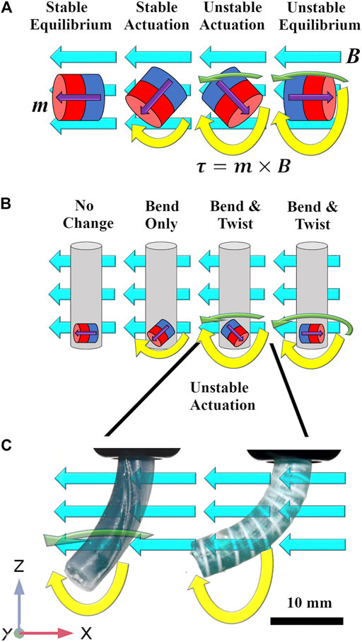
FIGURE 1. (A) Magnets in free space subject to a homogeneous actuating field [
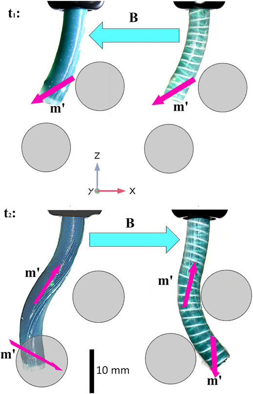
FIGURE 2. A minimal reproducible example of the impact of magnetic instability arising during manipulator navigation [as introduced in Lloyd et al. (2020b)]. Specific magnetization profiles and time variant actuating fields achieve follow-the-leader motion without imparting contact forces on the surrounding environment. Here, deformed magnetization vectors (m′) are shown as purple arrows and applied fields (B, which change with respect to time) as turquoise (referential magnetizations are omitted to avoid clutter but are shown in the supporting video and in Section 5). The range of magnetization vectors required to achieve desired profiles generates unavoidable instabilities where the angle between m and B is obtuse. As can be seen bottom left, the unreinforced manipulator is prone to twist about the, lower resistance, local z-axis causing a loss of desired deformation; this twist is also clearly shown in the Supplementary Video 1. If the manipulator was rotated
One potential solution for improving open-loop control of these soft robots is to produce an anisotropic elasticity distribution by reinforcing the elastomer with higher stiffness fibers in order to restrict torsion whilst still permitting bending. This approach has parallels with organically evolved systems such as the collagen fiber reinforcing of the earthworm and related invertebrates, frequently referenced by the soft robotics community Calderón et al. (2016). Following this concept, Kreig and Mohseni Krieg and Mohseni (2017) investigated high deformation anisotropic strain restriction and the geometric arrangement of fibers in elastomeric sheets. The commonly employed Mckibben artificial muscle Connolly et al. (2015) consists of a pneumatic bladder providing a uniform hydrostatic pressure and strain restricting fibers capable of producing a range of motion primitives Marchese et al. (2015), Connolly et al. (2017). More recently fluidic elastomer actuators have been developed and extensively exploited to offer a diverse range of pre-programmed mechanical responses to pneumatic pressure Polygerinos et al. (2015), Zhang et al. (2020). Strain restriction has proved highly effective for soft pneumatic actuators, however, this approach has yet to be applied within the field of magnetic CM research.
In this preliminary study we demonstrate the application of strain-limiting fiber reinforcement within magnetically actuated soft CMs for improved open-loop actuation stability. Magnetic CMs have their own specific challenges, notably, small-scale manufacturing, small actuation wrenches and unique input instabilities. Here we present a numerical analysis of the potential usefulness of fiber reinforcement which has previously never been proposed or explored. Our experimental work is for validation purposes only and significant development will be required particularly around fabrication and control before we can perform a full experimental analysis.
The specific application being considered is a multi-segment shape forming CM, or tentacle, with multiple magnetic elements as introduced in Lloyd et al. (2020a). Here we demonstrate using a single prototypical 2-segment design, as shown in the supporting video, which represents a subset of the full shape forming CM. The workflow through the paper is as follows: In Section 2 we set out our goals and research methods. In Section 3 we define the underlying theory behind the magnetically actuated elastomeric catheter and our associated numerical model. In Section 4 we present the results of our single segment optimization and in Section 5 we extend the study into a multi-segment design including fabrication and experimental evaluation. We conclude and discuss in Section 6.
2 Problem Definition
An algorithm for the selection of a magnetization profile and actuating fields for a fully shape forming catheter was demonstrated, in a virtual environment, in Lloyd et al. (2020b). The contribution of this work was to develop an optimization routine to derive specific magnetization profiles and time variant actuating fields to achieve follow-the-leader motion without imparting contact forces on the surrounding environment during navigation. One unavoidable outcome of this insertion process is a number of potentially unstable actuation arrangements. Referring to Figure 2, it can be observed in the second time step (
The objective of our work is to minimize the twisting primitive whilst maximizing the bending primitive, thus allowing practicable shape forming under a wider range of magnetization-magnetic field conditions. There are many potential solutions to the general problem of twist minimization in CMs but we are constrained by certain application specific requirements. In order to preserve the softness and malleability of the manipulator, and given the very low wrenches involved, we must employ soft, flexible reinforcing material in a sparse manner to produce anisotropic response to actuation. Specifically, we are attempting to minimize helical strain whilst allowing axial strain using only soft material. As such, our proposed solution to this multivariate problem, as inspired by Connolly et al. (2015), Polygerinos et al. (2015), Connolly et al. (2017) and Krieg and Mohseni (2017) uses a double (and therefore symmetrical) helix of reinforcing fiber.
To quantify prospective designs, we established baseline tests using a Finite Element (FE) simulation of a 20 mm long × 6 mm diameter elastomeric catheter as shown in Figure 3. A single 3.2 mm × 3.2 mm cylindrical permanent magnet (PM) is embedded at the tip (PM’s center 2 mm from the distal end) and the catheter is secured at its proximal end. The axis of magnetization of the PM was aligned in the positive x direction as indicated by the red arrows in Figure 3. The bending primitive was tested by applying a uniform magnetic field, B, in the negative z direction (Figure 3A). This actuating field generates a magnetic moment about the positive y axis and thus results in pure bend. The same sample, when subject to a B field in the positive y direction (Figure 3B), generates a magnetic moment about the positive z axis and thus results in pure twist. With these test cases we separate the two deformation primitives which, in most realistic states, will co-exist. We use this separation to assess the relative susceptibility of a range of designs to the two primitives before they are combined in experimental prototypes.
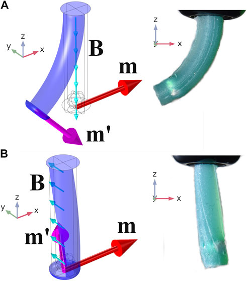
FIGURE 3. Pure bending about y(A) and pure twisting about z(B). The unreinforced Single Segment demonstrating the two non-trivial motion primitives (Pure bending about x and y are characteristically identical). On the left are isometric views of numerical simulations and on the right, planar (x–z) images of unreinforced prototypes. Referential magnetization vectors (m) are shown as red arrows, deformed magnetization vectors (m′) as purple and applied fields (B) as turquoise. Simulations recreated experimental results for the range
Evaluating designs using FE simulation allows exploration of a wide range of design properties. Here we explore variations in elastic modulus of elastomer
3 Modeling and Simulation
3.1 Material Model
We consider a soft catheter fabricated from elastomeric material (Ecoflex00-30, Smooth-On, United States) with strain limiting fibers made from Polylactic acid (PLA) (Material 1,613, Ultimaker, Netherlands), both with readily available material properties. The reinforcing fibers are assumed to be linearly elastic and are thus represented in the numerical model by the two constants; elastic modulus
where W is Strain energy, n = 3, is the order of the model, κ, is bulk modulus,
3.2 Magnetic Model
From Maxwell’s third equation,
3.3 Balance of Momentum
The torque acting on the tentacle as a consequence of the interaction of the actuating magnetic field and the magnetization of the embedded PM is counteracted by gravity and by the elastic properties of the material. In the case of the unreinforced tentacle this material response is exclusively generated by the isotropic bulk elasticity of the silicone. However, for the reinforced tentacle we must also include the tensile and compressive stresses of the fibers. At all measured states the system was assumed quasi-static and as such the sum of all forces and the sum of all torques at all points must be zero.
A reduction in the ratio of bending to twisting stiffness is achieved by constraining the principle stretches of the twisting primitive using a material of far greater elastic modulus than the host elastomer
It is possible to characterize elastic moduli as a function of direction, to accommodate a difference between tensile and compressive stiffness. This characteristic is explored in some depth in Cappello et al. (2018) and would add significant complication to any analysis of fiber reinforcing. In the presented case we only consider reinforcing materials that can be considered to have a scalar elastic modulus.
3.4 Finite Element Method
The simulation environment was built in COMSOL mutiphysics v5.5 (COMSOL AB, Stockholm, Sweden) using the solid mechanics module to simulate the silicone elastomer and PM’s, and the truss module to simulate the fiber reinforcement.
NdFeB magnets have an elastic modulus of 150 GPa, (
The material employed for the reinforcing fiber is, in the numerical model, represented as a chain of truss elements. These elements are attached to the solid mechanics module using a prescribed displacement option effectively imposing zero slippage between the fibers and the elastomer; a valid assumption when interactive shear forces are sufficiently low.
All models were meshed using tetrahedral elements, free-formed by the COMSOL auto-mesh generator. The larger, two segment, simulation required 26,000 tetrahedral finite elements and took 60 s to converge utilizing Newton-Raphson iterations within the MUltifrontal Massively Parallel sparse direct Solver (MUMPS) option. For a parametric sweep of applied actuating field |B| from −20 to +20 mT in 1 mT increments this represents a 40 min run-time on a 3.2 GHz, 32 GB, 16 core Intel Xeon Gold processor.
4 Single Segment Optimization
Here we isolate bending and twisting in our single segment numerical simulations with the objective of assessing the impact of variations in our design variables on these respective primitives. The optimized solution which we converge upon will then be implemented for a multi-segment tentacle in Section 5. The four design variables considered in this study are; fiber angle,
4.1 Variation in Fiber Angle and Number of Helices
For the purposes of this study fiber angle
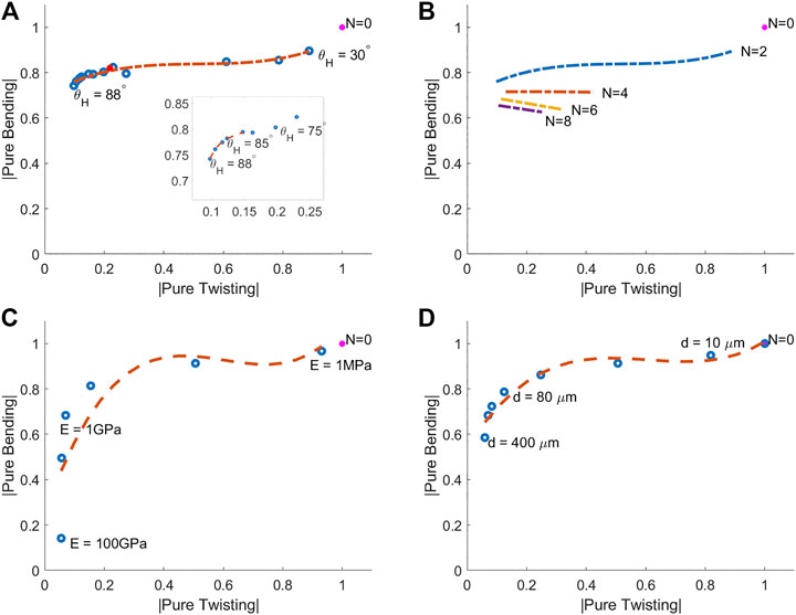
FIGURE 4. Pure bending vs. pure twisting for various helix arrangements under 10 mT actuation. (A) Variation in fiber angle (
A higher fiber angle increases the length of fiber per unit length of manipulator (as pitch is proportional to the tangent of the negative of fiber angle). An alternative method for increasing fiber length per unit length of the manipulator is through the use of additional concentric helices. To maintain symmetry, these helices must be increased in pairs (one left-handed helix and one right-handed helix). Figure 4B shows the effect of varying the number of helices for a variety of fiber angles (where filament diameter
4.2 Variation in Elastic Modulus and Filament Radius
The elastic and geometric characteristics of the fiber reinforcement, relative to the elastomer, are crucial to successful strain restriction. If the elastic modulus or fiber diameter are too high then bending flexibility will be lost and if too low then twisting will be unconstrained and instability will persist. There is, however, a fundamental inter-relationship between the two variables. The uni-axial stiffness of a truss member is a linear function of
In theory, there are infinite ways to produce an
5 Shape Forming Tentacle
Figure 5 demonstrates, for an unstably actuated (
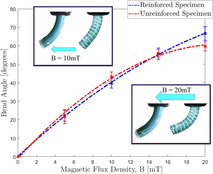
FIGURE 5. Actuating magnetic flux density (|B|) against bend angle (θ) for unreinforced and reinforced single segment specimens, magnetized in the unstable orientation (
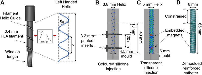
FIGURE 6. Fabrication process of the reinforced magnetic catheter. (A) Helix formation with a 0.4 mm PLA fiber at a fiber angle of
5.1 Numerical Result
To demonstrate minimization of unstable twisting in the FE simulation we show Figures 7A,C. Optimal fiber reinforcement would represent PLA
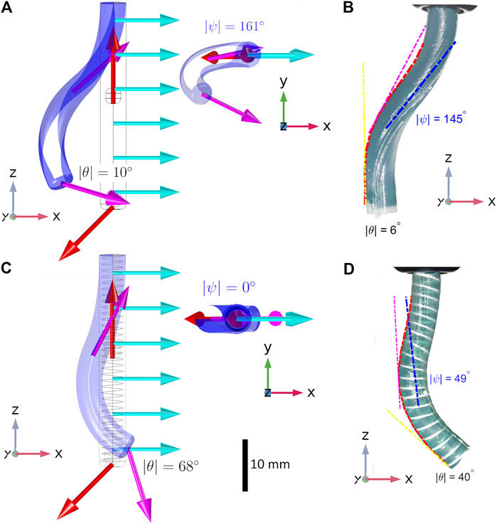
FIGURE 7. Both reinforced and unreinforced specimens have identical referential magnetizations (red arrows in the numerical simulation) and are subject to the same actuating field (
5.2 Fabrication
To verify the findings from the FE simulation, we fabricated a design of the same dimensions. Figure 6 outlines the full fabrication process. Helices were fabricated from white PLA (Material 1,613, Ultimaker, Netherlands). Filament was extruded to a fiber of diameter 0.4 mm (
5.3 Experimental Result
To evaluate the fabricated samples, an actuating field was supplied using a uni-directional Helmholtz coil (DXHC10-200, Dexing Magnet Tech. Co., Ltd., Xiamen, China) as shown in Figure 8. The response to actuation (taken at
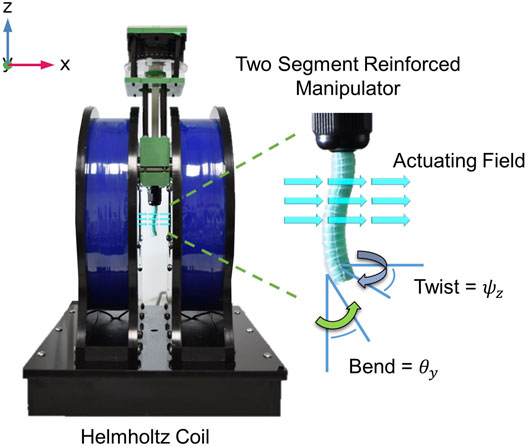
FIGURE 8. A sample tentacle under actuation in the Helmholtz coil and the two motion primitives being measured: Twist about the local z axis (ψ) and Bend about the y axis (θ).
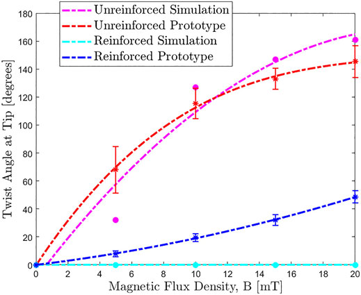
FIGURE 9. Actuating magnetic flux density (|B|) against twist angle at tip (ψ) for the unreinforced and reinforced two segment tentacles shown in Figure 7. In the reinforced simulation (yellow), twist is completely eradicated for all applied fields. Whilst this success isn’t fully recreated in the reinforced experimental protoype (blue) there is still a significant reduction in unwanted twist across the full spectrum of actuation.
Bend angle of the lower PM is derived from the derivative (yellow hatched line) of a fitted second order polynomial (red hatched curve: Polyfit, Matlab version R2018b, the MathWorks, Natick, MA, United States). The angle of twist has been determined by fitting a first order polynomial to imprinted longitudinal lines down the trunk of the segment and measuring the angle ϕ between this and the angle of bending at the same z position. This helix angle determines the angle of twist ψ via the relationship:
All experiments were repeated three times under identical conditions. Figures 7A,B are unreinforced and therefore more prone to the twisting instability. In the unreinforced FE model (Figure 7A) we observe a distal twist angle of
6 Conclusion and Future Work
In this introductory work, we demonstrate the issue of instability of magnetic CMs under certain configurations of B and m. We then applied fiber reinforcement, for the first time in magnetic soft robotics, as a means to mitigate this issue. Using our reinforcing at an optimized fiber angle of
Limitations in fabrication capabilities have restricted our experimental twist reduction capacity. For practical, large deformation navigations such as gastrointestinal and endovascular interventions we need to exhibit closer reconciliation to numerical results. As such, we hope to develop an automated, miniaturized, and therefore more robust and versatile fabrication technique for variable reinforcement of magnetic catheters. Additionally a more exhaustive optimization procedure for the geometric characteristics of the reinforcement is desirable. In order for the simulation to more closely recreate reality we would also incorporate the unavoidable low magnitude, out of plane input errors in the actuating field which always occur in the real world and also simulate the interaction between multiple embedded permanent magnets. Both small but present contributions to simulation error.
These developments will allow us to move beyond this preliminary phase of study into more thorough and expansive experimental demonstrations. This should offer closer agreement to simulated outcomes and a greater reduction in unwanted twisting which will start to open up the possibility of practical, real-world navigation. From this initial platform, we can look forward to producing multiple-segment catheters capable of stable open-loop navigation through trajectories taken from pre-operative patient images. With this contribution we have taken a step toward fulfilling the potential of magnetic shape forming tentacles for navigation through specific anatomical constraints in a safe and stable manner.
Data Availability Statement
The original contributions presented in the study are included in the article/Supplementary Material, further inquiries can be directed to the corresponding author.
Author Contributions
PL contributed to the design conception, simulation, experimental setup, data analysis and manuscript preparation. ZK contributed to prototyping, experimental design and manuscript revision. ML contributed to simulation and experimental setup. OO contributed to the design conception, experimental design, data analysis and manuscript revision. JC contributed to the design conception, prototyping, experimental design and setup and manuscript revision. PV contributed toward scientific support and manuscript revision.
Funding
Research reported in this article was supported by the Royal Society, by the Engineering and Physical Sciences Research Council (EPSRC) under grant number EP/R045291/1, and by the European Research Council (ERC) under the European Union’s Horizon 2020 research and innovation program (grant agreement No. 818045). Any opinions, findings and conclusions, or recommendations expressed in this article are those of the authors and do not necessarily reflect the views of the Royal Society, EPSRC, or the ERC.
Conflict of Interest
The authors declare that the research was conducted in the absence of any commercial or financial relationships that could be construed as a potential conflict of interest.
The handling Editor declared a past co-authorship with the authors JC, PV.
Supplementary Material
The Supplementary Material for this article can be found online at: https://www.frontiersin.org/articles/10.3389/frobt.2021.715662/full#supplementary-material
References
Barducci, L., Pittiglio, G., Norton, J. C., Obstein, K. L., and Valdastri, P. (2019). Adaptive Dynamic Control for Magnetically Actuated Medical Robots. IEEE Robot. Autom. Lett. 4, 3633–3640. doi:10.1109/lra.2019.2928761
Bira, N., Dhagat, P., and Davidson, J. R. (2020). A Review of Magnetic Elastomers and Their Role in Soft Robotics. Front. Robot. AI 7, 146. doi:10.3389/frobt.2020.588391
Burgner-Kahrs, J., Rucker, D. C., and Choset, H. (2015). Continuum Robots for Medical Applications: A Survey. IEEE Trans. Robot. 31, 1261–1280. doi:10.1109/tro.2015.2489500
Calderón, A. A., Ugalde, J. C., Zagal, J. C., and Pérez-Arancibia, N. O. (2016). “Design, Fabrication and Control of a Multi-Material-Multi-Actuator Soft Robot Inspired by Burrowing Worms,” in 2016 IEEE International Conference on Robotics and Biomimetics (ROBIO), Qingdao, China, 3-7 Dec. 2016, 31–38.
Cappello, L., Galloway, K. C., Sanan, S., Wagner, D. A., Granberry, R., Engelhardt, S., et al. (2018). Exploiting Textile Mechanical Anisotropy for Fabric-Based Pneumatic Actuators. Soft robotics 5, 662–674. doi:10.1089/soro.2017.0076
Connolly, F., Polygerinos, P., Walsh, C. J., and Bertoldi, K. (2015). Mechanical Programming of Soft Actuators by Varying Fiber Angle. Soft Robotics 2, 26–32. doi:10.1089/soro.2015.0001
Connolly, F., Walsh, C. J., and Bertoldi, K. (2017). Automatic Design of Fiber-Reinforced Soft Actuators for Trajectory Matching. Proc. Natl. Acad. Sci. 114, 51–56. doi:10.1073/pnas.1615140114
da Veiga, T., Chandler, J. H., Lloyd, P., Pittiglio, G., Wilkinson, N. J., Hoshiar, A. K., et al. (2020). Challenges of Continuum Robots in Clinical Context: a Review. Prog. Biomed. Eng. 2, 032003. doi:10.1088/2516-1091/ab9f41
Diller, E., Zhuang, J., Zhan Lum, G., Edwards, M. R., and Sitti, M. (2014). Continuously Distributed Magnetization Profile for Millimeter-Scale Elastomeric Undulatory Swimming. Appl. Phys. Lett. 104, 174101. doi:10.1063/1.4874306
Edelmann, J., Petruska, A. J., and Nelson, B. J. (2017). Magnetic Control of Continuum Devices. Int. J. Robotics Res. 36, 68–85. doi:10.1177/0278364916683443
Kim, Y., Parada, G. A., Liu, S., and Zhao, X. (2019). Ferromagnetic Soft Continuum Robots. Sci. Robotics 4, eaax7329. doi:10.1126/scirobotics.aax7329
Krieg, M., and Mohseni, K. (2017). Relative Planar Strain Control and Minimizing Deformation Work in Elastomeric Sheets via Reinforcing Fiber Arrays. Composites Sci. Technol. 142, 50–64. doi:10.1016/j.compscitech.2017.01.014
Lloyd, P., Hoshiar, A. K., da Veiga, T., Attanasio, A., Marahrens, N., Chandler, J. H., et al. (2020a). A Learnt Approach for the Design of Magnetically Actuated Shape Forming Soft Tentacle Robots. IEEE Robotics Automation Lett. 5, 3937–3944. doi:10.1109/lra.2020.2983704
Lloyd, P., Pittiglio, G., Chandler, J. H., and Valdastri, P. (2020b). “Optimal Design of Soft Continuum Magnetic Robots under Follow-The-Leader Shape Forming Actuation,” in 2020 International Symposium on Medical Robotics (ISMR), Atlanta, GA, USA, 18-20 Nov. 2020, 111–117. doi:10.1109/ISMR48331.2020.9312943
Lum, G. Z., Ye, Z., Dong, X., Marvi, H., Erin, O., Hu, W., et al. (2016). Shape-programmable Magnetic Soft Matter. Proc. Natl. Acad. Sci. 113, E6007–E6015. doi:10.1073/pnas.1608193113
Marchese, A. D., Katzschmann, R. K., and Rus, D. (2015). A Recipe for Soft Fluidic Elastomer Robots. Soft robotics 2, 7–25. doi:10.1089/soro.2014.0022
Norton, J. C., Slawinski, P. R., Lay, H. S., Martin, J. W., Cox, B. F., Cummins, G., et al. (2019). Intelligent Magnetic Manipulation for Gastrointestinal Ultrasound. Sci. Robotics 4, 1–14. doi:10.1126/scirobotics.aav7725
Pittiglio, G., Chandler, J., Richter, M., Venkiteswaran, V., Misra, S., and Valdastri, P. (2020). “Dual-arm Control for Enhanced Magnetic Manipulation,” in IEEE/RSJ International Conference on Intelligent Robots and Systems IROS 2020: Consumer Robotics and Our Future, Las Vegas, NV, USA, 24 Oct.-24 Jan. 2021.
Polygerinos, P., Wang, Z., Overvelde, J. T., Galloway, K. C., Wood, R. J., Bertoldi, K., et al. (2015). Modeling of Soft Fiber-Reinforced Bending Actuators. IEEE Trans. Robotics 31, 778–789. doi:10.1109/tro.2015.2428504
Steck, D., Qu, J., Kordmahale, S. B., Tscharnuter, D., Muliana, A., and Kameoka, J. (2019). Mechanical Responses of Ecoflex Silicone Rubber: Compressible and Incompressible Behaviors. J. Appl. Polym. Sci. 136, 47025. doi:10.1002/app.47025
Vrooijink, G. J., Abayazid, M., and Misra, S. (2013). “Real-time Three-Dimensional Flexible Needle Tracking Using Two-Dimensional Ultrasound,” in 2013 IEEE International Conference on Robotics and Automation, Karlsruhe, Germany, 6-10 May 2013 (IEEE), 1688–1693.
Yeoh, O. H. (1993). Some Forms of the Strain Energy Function for Rubber. Rubber Chem. Technol. 66, 754–771. doi:10.5254/1.3538343
Keywords: magnetic continuum manipulators, soft robotics, continuum robots, magnetic actuation, soft surgical robots, magnetic soft continuum robots, fiber reinforced soft robots
Citation: Lloyd P, Koszowska Z, Di Lecce M, Onaizah O, Chandler JH and Valdastri P (2021) Feasibility of Fiber Reinforcement Within Magnetically Actuated Soft Continuum Robots. Front. Robot. AI 8:715662. doi: 10.3389/frobt.2021.715662
Received: 27 May 2021; Accepted: 24 June 2021;
Published: 08 July 2021.
Edited by:
Long Wang, Stevens Institute of Technology, United StatesReviewed by:
Arun Srivatsan Rangaprasad, Apple, United StatesHao Liu, Shenyang Institute of Automation (CAS), China
Copyright © 2021 Lloyd, Koszowska, Di Lecce, Onaizah, Chandler and Valdastri. This is an open-access article distributed under the terms of the Creative Commons Attribution License (CC BY). The use, distribution or reproduction in other forums is permitted, provided the original author(s) and the copyright owner(s) are credited and that the original publication in this journal is cited, in accordance with accepted academic practice. No use, distribution or reproduction is permitted which does not comply with these terms.
*Correspondence: Peter Lloyd, bWVuOXBybEBsZWVkcy5hYy51aw==