 Stanislav Sikulskyi1
 Zefu Ren1
 Danayit T. Mekonnen1Aleiya Holyoak2
 Rishikesh Srinivasaraghavan Govindarajan1
 Daewon Kim1*
- 1Department of Aerospace Engineering, Embry-Riddle Aeronautical University, Daytona Beach, FL, United States
- 2Department of Mechanical Engineering, Embry-Riddle Aeronautical University, Daytona Beach, FL, United States
Dielectric elastomer actuator (DEA) is a smart material that holds promise for soft robotics due to the material’s intrinsic softness, high energy density, fast response, and reversible electromechanical characteristics. Like for most soft robotics materials, additive manufacturing (AM) can significantly benefit DEAs and is mainly applied to the unimorph DEA (UDEA) configuration. While major aspects of UDEA modeling are known, 3D printed UDEAs are subject to specific material and geometrical limitations due to the AM process and require a more thorough analysis of their design and performance. Furthermore, a figure of merit (FOM) is an analytical tool that is frequently used for planar DEA design optimization and material selection but is not yet derived for UDEA. Thus, the objective of the paper is modeling of 3D printed UDEAs, analyzing the effects of their design features on the actuation performance, and deriving FOMs for UDEAs. As a result, the derived analytical model demonstrates dependence of actuation performance on various design parameters typical for 3D printed DEAs, provides a new optimum thickness to Young’s modulus ratio of UDEA layers when designing a 3D printed DEA with fixed dielectric elastomer layer thickness, and serves as a base for UDEAs’ FOMs. The FOMs have various degrees of complexity depending on considered UDEA design features. The model was numerically verified and experimentally validated through the actuation of a 3D printed UDEA. The fabricated and tested UDEA design was optimized geometrically by controlling the thickness of each layer and from the material perspective by mixing commercially available silicones in non-standard ratios for the passive and dielectric layers. Finally, the prepared non-standard mix ratios of the silicones were characterized for their viscosity dynamics during curing at various conditions to investigate the silicones’ manufacturability through AM.
1 Introduction
Dielectric elastomer actuator (DEA) is one of the electroactive polymers that has attracted immense interest in the field of soft robotics and electronics due to its fast and reversible electromechanical response, large strain capabilities, and high specific energy density (Duduta et al., 2019; Hajiesmaili and Clarke, 2021). DEA consists of a dielectric elastomer (DE) sandwiched between two compliant electrodes and operates through an electrostatic pressure mechanism when high voltage is applied to the electrodes. For the planar DEA, actuation mode occurs in the form of thickness contraction that is effectively translated to in-plane expansion due to typical elastomer materials being nearly incompressible (Figure 1A). To enhance deflection capabilities, the unimorph DEA (UDEA) configuration possesses an additional external passive layer that translates DEA’s in-plane expansion into the bending of the entire actuator (Figure 1B). As a result, considerably larger deflection can be achieved by UDEA at lower strains (Kim et al., 2022).
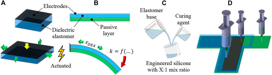
FIGURE 1. Structure and actuation mode of a (A) planar and (B) unimorph DEA configurations, (C) silicone modification through various mix ratios of elastomer base and curing agent, and (D) 3D printing of each UDEA layer through contact dispensing (direct ink writing).
The planar DEA actuation performance is driven by its materials and layers’ thicknesses and is often described with one of the figures of merit (FOM) as in Eq. 1, which shows the amount of actuation strain in the thickness direction (McKay et al., 2009).
where
Meanwhile, modeling UDEA is more complicated than planar DEAs from the layers’ design standpoint and lacks a simple tool like FOM for material selection and design optimization despite numerous static and dynamic analytical modeling approaches with elastic, hyperelastic, and viscoelastic DE materials (Lau et al., 2011; Kadooka et al., 2016; Kadooka, 2017; Haghiashtiani et al., 2018; Gareis and Maas, 2021; Hajiesmaili and Clarke, 2021). Besides accounting for DE layer properties mentioned above, the thickness and modulus of each layer, including the passive layer and electrodes, contribute to overall multilayer beam stiffness. Additionally, soft unimorph actuators largely adopt their modeling approaches from piezoelectric unimorph actuators (Wang and Cross, 1998; Ballas, 2007; Araromi and Burgess, 2012). As a result, numerous effects, such as electrode stiffness, large deflection, and deformation under weight, are often overlooked in the unimorph actuator design process. Therefore, there is a need for a simple analytical model that considers important features of soft unimorph actuators with reasonable simplifications and UDEA FOM that allows simplified material selection and design optimization.
Table 1 shows 3D printed and conventionally fabricated UDEAs found in literature, their reported material characterization and actuation performance, and potential optimized design performance based on the model derived and validated in this paper. Only actuators with known parameters and conventional unimorph structure are reported in the table, despite the achieved large actuation of some other actuators (Lau et al., 2011; Pu et al., 2022). In the table, some deviation between experimental curvatures and analytical FOM can be noticed for some studies which is attributed to material characterization and thickness measurements of UDEA layers. The table shows that single- and multilayer UDEA in numerous studies achieved high values of analytical curvatures of the fabricated designs relative to the maximum possible curvatures of the optimized design. However, the passive layer thicknesses were far from optimum values for most of studies despite actuators’ high performance. That is explained by gently sloped FOM curves with respect to passive layer thickness, when passive layer has comparable Young’s modulus to the DE layer. Meanwhile, performance of actuators with thin and stiff passive layers is compromised considerably if far from optimum passive layer thicknesses are used (Araromi and Burgess, 2012; Sikulskyi et al., 2020).
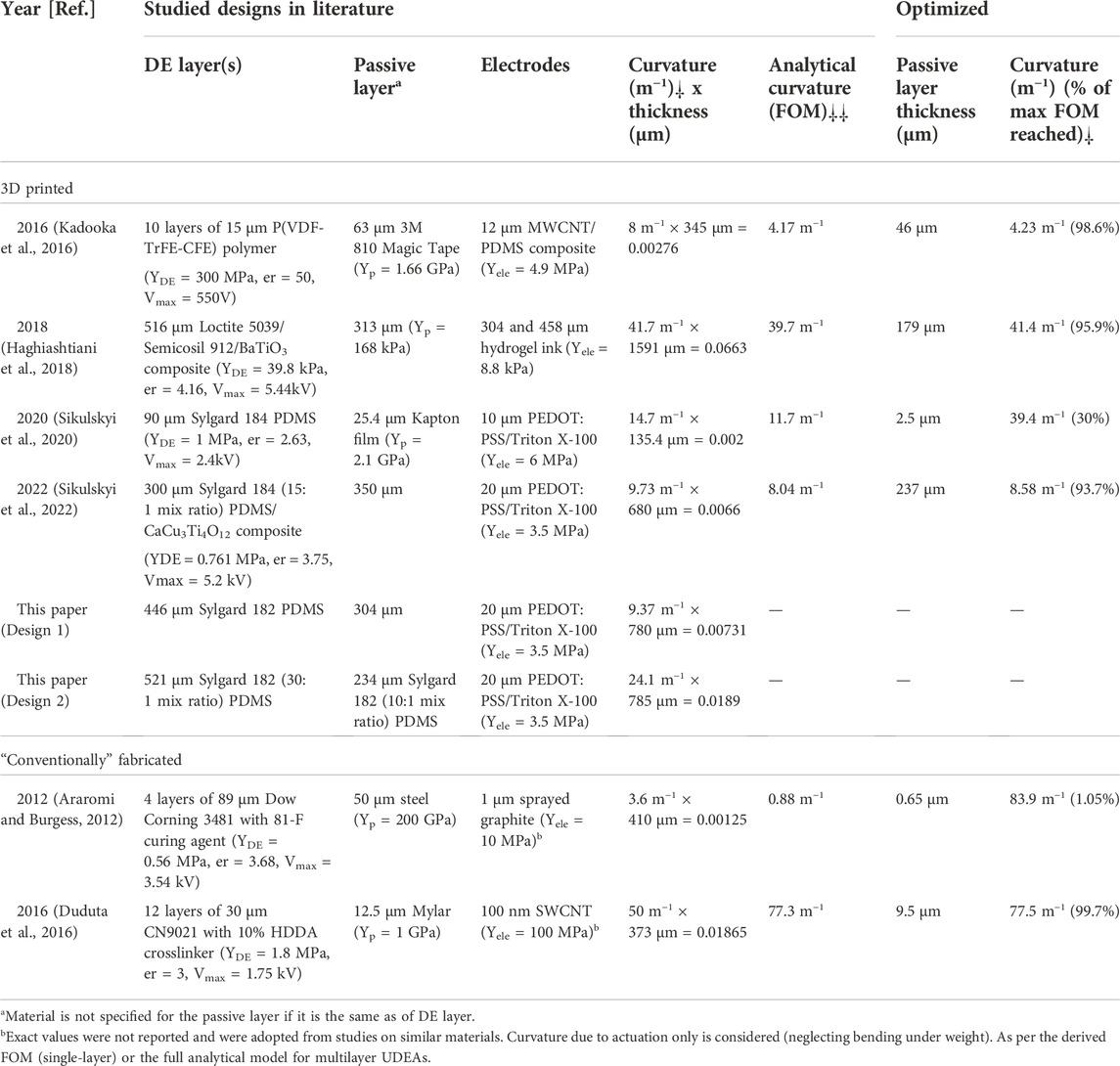
TABLE 1. Tested unimorph DEA designs in literature and their optimized performance.
Fabrication is another crucial aspect of DEA development due to its immense impact on the actuator performance. Besides, their multilayer and multimaterial structure makes DEA fabrication an effort- and time-consuming process. As a result, additive manufacturing (AM) or 3D printing is one of the promising techniques for automating DEA fabrication and enabling complex biomimetic soft actuators (Chen et al., 2021; Kim et al., 2022). Therefore, characterizing material manufacturability is an important aspect of high-performance DEA design implementation through 3D printing. For instance, viscosity is one of the primary properties of uncured elastomer that enables printing, determines printing parameters, and drives the printed material rheology through traditional dispensing and newly developed techniques (Chortos et al., 2020; Schlatter et al., 2020; Chortos et al., 2021; Jiang et al., 2021; Regis et al., 2021; Shintake et al., 2021; Li et al., 2022; Naniz et al., 2022). In the literature, viscosity and storage shear modulus are measured after material preparation. However, there is a lack of studies on how material viscosity changes directly after mixing and during crosslinking (curing) process. Therefore, investigation of the post-mixing viscosity dynamics and manufacturability of common elastomers for 3D printing of soft robotics is an important supporting analysis of this study. To perform the analysis, several polydimethylsiloxanes (PDMS) elastomer compositions were mixed and characterized for their rheology and practical handling time for the contact dispensing AM method. PDMS Sylgard 184 was used as the material is commonly utilized in soft material technologies. Two similar PDMS materials, i.e. Sylgard 186 and Sylgard 182, were also studied due to its additional softness (186) and its long curing time (182), relatively underutilized characteristic allowing more prolonged 3D printing session without replacing the material. As a method to improve DEA electromechanical actuation, different mixing ratios of elastomer base (Part A) and platinum-based curing agent (Part B) were investigated for Sylgard 182 (Figure 1C) (Chen et al., 2019; Vaicekauskaite et al., 2019). Various optimized UDEA designs were 3D printed and tested to validate the derived model, FOM, and materials’ printability (Figure 1D).
2 Results and discussion
2.1 Analytical modeling
The derivation of an analytical model starts with analyzing the real actuator’s behavior and discussing what simplifications and assumptions are adequate to implement into the mathematical model. Major aspects to consider here are material, geometry, and loads.
Material. Due to the bending type of deformation, UDEAs produce large deflection at relatively low strain. Particularly, some of the best performing UDEAs produce considerable deformations with the bending angle up to 270° at the tip of the actuator while the maximum strain does not reach 5% in the actuator (Pu et al., 2022). While being material sensitive, such strains do not deviate the compressive modulus from its initial zero-strain value. Therefore, a linear material model can be implemented for most materials besides those that can behave very nonlinearly at the abovementioned low strain values.
Geometry. Several important aspects need to be discussed and addressed with respect to the geometry of UDEAs:
• Structure type. Having layers that are much thinner than their width and length, UDEAs are essentially plate-like structures. Thus, in-plane actuation of the DE layer results in UDEA curvature in both directions. While curvature along the longer side of UDEAs creates the desired deflection of the actuator, the transverse curvature increases its stiffness and negatively affects actuation capabilities. Furthermore, the plate’s bending stiffness is larger than the beam stiffness (Ugural, 2017). UDEA can be modeled as a plate structure to account for these effects. However, most UDEAs have a moderately larger length than width to effectively produce curvature in the desired direction. Hence, modeling UDEA as multilayer beams is a case-sensitive application but is appropriate for most designs in the literature (Table 1). Therefore, this work models UDEAs as beams to result in an overcomplicated analytical model and FOM.
• Beam model. As mentioned above, UDEAs are typically thin beams with high length-to-thickness ratios. Thus, an Euler-Bernoulli beam model and its negligence of shear stress are appropriate to model UDEA.
• Unimorph DEA current configuration. During actuation, DEA reduces its thickness which is accounted in Maxwell pressure equation by utilizing a current thickness of DE film. When UDEA actuates, this thinning reduces actuator’s bending stiffness and is an important factor to account for UDEAs.
• Geometrical nonlinearity. Numerous UDEAs have demonstrated large deflection and curvature capabilities thanks to their bending nature, material softness, and thin beam geometry. Accounting for geometrical nonlinearities such as large rotation and deflection is not trivial in some cases. In this study, large deflection is not considered as it is not needed to derive the FOM for unimorph DEA but is essential for its accurate modeling.
• Insulation material. It is almost always considered that electrodes occupy the entire area of DE films. However, practically all DEAs require insulation material to prevent the formation of a through-the-air circuit between the electrodes due to the high voltage applied. Despite the required amount of the insulation material being small and close to the DE layer thickness, much larger insulation can be practically implemented depending on the fabrication technique.
Loads. Typical materials for DEA include silicones, acrylic elastomers, rubbers, and more rarely stiffer dielectric materials, as well as compliant electrodes. The passive layers of UDEAs can often be made of stiffer material but usually are made thin not to hinder actuation capabilities. As a result, UDEAs typically bend considerably under their weight, making it one of the preferred loads to be accounted in the modeling.
2.1.1 Small deflection analytical model
The derivation starts with the Euler-Bernoulli beam model, which assumes the planes perpendicular to the beam’s neutral axis (NA) to stay perpendicular upon bending. Correspondingly, longitudinal strain,
where
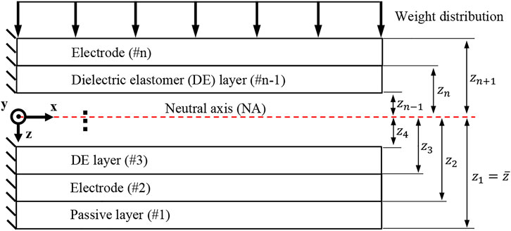
FIGURE 2. Multilayer unimorph DEA structure.
Meanwhile, longitudinal strain in each layer of material of UDEA, i.e., passive layer, DE layers, and electrodes, can be shown as a summation of the mechanical elastic strain due to deformation compatibility between the layers,
The mechanical strain in the ith layer is simply the mechanical stress over the material’s Young’s modulus,
where
where
where
Once the relation between the strains in each layer is established as
where
Solving Eq. 5 for the NA location results in Eq. 7, which can be rewritten for curvature as in Eq. 8. Note that the NA location depends on both multilayer beam properties and DEA layer actuation. Similarly, Eq. 6 can be solved for curvature as in Eq. 9. The solution process is demonstrated in the Supplementary Material. Now, NA location,
For the small deflection bending, the strain-deformation relation is expressed by Eqs 10, 11. The actuator’s deflection,
where
The derived analytical model was validated experimentally by comparing deflections of a selected UDEA design under the weight only and at maximum applied electric field of 22.2 V/μm reached in the experiment (Figure 3). The UDEA design produces moderate bending under its weight and has considerable actuation; its selection is shown in the result section. Both passive and DE layers were assumed to be made of Sylgard 182 (10:1) with PEDOT:PSS-based electrodes used in this study. The difference between analytical and experimental deflections are about 1% for the bending at no electric field, and less than 3% at the 22.2 V/μm. From the comparison without applied electric field, the practically identical deformed UDEA shapes suggest that the stiffness and weight loading of the multilayer beam are described correctly in the derived model. The larger difference for the actuated case was attributed to a larger deflection and corresponding geometrical nonlinearity, not considered in the analytical model. Therefore, a numerical modeling with a linear material models and accounting for geometrical nonlinearities was performed. Commercial finite element method (FEM) software COMSOL Multiphysics was utilized to obtain numerical solutions of the UDEA actuation in the cantilever mode. In the simulation, the passive layer and electrodes were modeled as linearly elastic materials, while the DE layer was modeled as a linear dielectric to enable electromechanical coupling. Same Young’s moduli of the materials were selected in the numerical simulation as in the analytical model as specified in the figures with Poisson’s ratio of 0.49. The comparison demonstrated a practically negligible difference between the numerical and analytical deflections at no electric field for the selected UDEA design. As the electric field of 22.2 V/μm was applied, the difference in deflections was still less than 1%. To illustrate the effect of large deflection geometrical nonlinearity, the electric field of 60 V/μm, the highest electric field reached for 3D printed DEAs in the literature, was applied in the numerical and analytical models (Schlatter et al., 2020). At 60 V/μm applied electric field, UDEA rotation becomes more apparent, violating linear beam geometry assumptions and considerably changing weight distribution along the actuator. Therefore, while for the selected UDEA design, the deflection at practically achievable electric field can be estimated through the derived analytical model with a small error, further UDEA actuation would result in a deformed shape that is predicted inaccurately and require geometrical nonlinearities consideration.
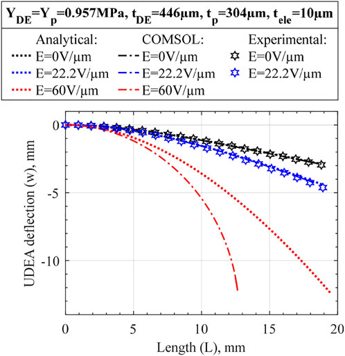
FIGURE 3. Deformed Unimorph DEA shape obtained using the derived small deflection analytical model and large deflection COMSOL Multiphysics FEM simulation for various loading/actuation cases. More actuation cases are presented in Supplementary Figure S2 to better illustrate the effect of large deflection on the selected UDEA design.
2.1.2 Figure of merit
Following the derived analytical models, a FOM was derived to provide a straightforward tool to optimize the unimorph actuator design and quantify the performance of the passive, electrode, and DE layers’ materials. It is convenient to set the FOM to represent the curvature of the actuator that can be maximized without the concern of large deflection. Therefore, Eqs 8, 9 are used as the starting point to derive the uncomplicated FOM for UDEAs. Along the derivation, the following features and assumptions accounting for a typical UDEA structure are used to obtain and simplify the FOM expressions (the full derivation and additional comments are available in Supplemental Material):
1. Actuator’s weight can be neglected because the objective of FOM is to achieve maximum actuation.
2. Cross-section is rectangular with width,
3. A typical unimorph material layout starts with the passive layer and then alternates between the electrode and DE layers (
4. All DE layers have the same thickness, and all electrodes have the same thickness.
5. Same voltage potential difference (voltage) is applied to all electrodes.
6. Actuation strain,
According to the above assumptions, Eqs 8, 9 transform to Eqs 14, 15, respectively, for a multilayer unimorph actuator. However, an explicit expression for FOM cannot be obtained yet.
where
7. Furthermore, for a UDEA with a single DE layer (
8. Finally, similarly to a commonly used FOM for planar DEAs, electrodes’ contribution can be neglected (
Resulting in the optimum thickness-modulus ratio:
Derived FOMs (Eqs 16, 17) represent the achievable curvature of the UDEA at the highest possible applied electric field, which is the breakdown strength of the DE material,
Once the FOMs are derived for different degrees of UDEA simplification, the analysis of various design parameters on actuator’s performance is conducted in the following order. First, Eq. 17 shows the effect of DE and passive layers on UDEA performance and finds the optimum design while neglecting the electrode contribution. Then, Eq. 16 is used to show the stiffening effect of electrodes. Lastly, Eqs 14, 15 are used to show the effect of number of DE layers. Similarly to the material in the numerical analysis, the presented analysis of the derived FOM is performed with the DE material that has dielectric permittivity,
It is worth mentioning that the derived FOM and analytical model can be easily applied to unimorph actuator made of any material by replacing the DEA actuation strain
2.1.3 Effects of DE and passive layers
Despite being vastly simplified, Eq. 17 demonstrates numerous essential elements of UDEA actuation performance:
• As Eq. 17 shows, curvature is a hyperbolic function of actuator thickness if electrodes are neglected. Therefore, total actuator thickness largely drives unimorph actuation performance in terms of its curvature (Figure 4A). Thus, if actuators with different total thicknesses are compared and judged in terms of optimized material properties, appropriate criteria is curvature multiplied by thickness as was stated in (Pu et al., 2022).
• For the fixed actuator’s total thickness, the optimum ratios of modulus and thickness are known from the previous studies on piezoelectric unimorph actuators as
• Furthermore, for DEAs, especially 3D printed ones, manufacturing is the primary limitation for obtaining a thin, high-quality DE film for low-voltage actuation. This is attributed to the fact that breakdown failure happens at the location of DE film with the smallest thickness or the presence of some defect, such as air bubbles, voids, or trapped dust. Therefore, a more practical approach is where the elastomer thickness is fixed at the minimum adequately printable value, and the optimum modulus-thickness ratio is determined through Eq. 19. Figure 5 shows that using a thinner and stiffer passive layer for the fixed DE layer increases unimorph actuator performance. Notably, the optimum design is now located at
• Lastly, modifying DE material is another way of enhancing the actuation. From Eq. 17, it is apparent that increasing DE material’s relative dielectric permittivity or breakdown strength proportionally increases actuation performance. However, some methods to increase DE dielectric properties lead to material mechanical stiffening, e.g., through dielectric composites (Haghiashtiani et al., 2018; Pu et al., 2022; Sikulskyi et al., 2022). Per Eq. 17, the trade between DE modulus and dielectric properties can be expressed for a single-layer UDEA with completely compliant and thin electrodes as
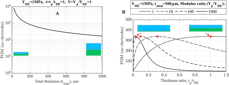
FIGURE 4. No-electrode FOM performance of unimorph DEA (A) for variable and (B) fixed total thickness. The optimum designs at
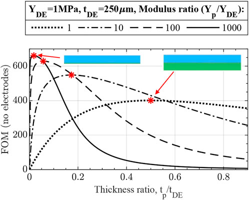
FIGURE 5. No-electrode FOM for unimorph DEA designs with fixed DE thickness demonstrating better performance of actuators with thinner and stiffer passive layers due to the smaller total thickness. The optimum designs are marked and match with the derived optimum ratio
2.1.4 Effects of electrodes
The effects of electrodes on UDEA’s actuation and optimized designs are demonstrated through the single-layer UDEA FOM (Eq. 16). Figure 6A demonstrates performance of a unimorph actuator with a fixed design of DE, passive layers, and various electrode designs. The curve representing
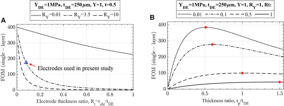
FIGURE 6. Effects of electrodes on unimorph DEA actuation evaluated through the single-layer FOM for unimorph DEAs with fixed (A) DE and passive layers, (B) modulus of all layers and DE thickness. For the fixed electrode, thickness and modulus are taken as for PEDOT:PSS-based electrodes used in present study.
2.1.5 Effects of multilayer unimorph DEA
Now, the effects of number of DE layers on multilayer UDEA (MUDEA) are analyzed. The main benefit of breaking the DE layer into multiple layers with the same cumulative thickness is actuation at a reduced voltage that is inversely proportional to the thickness of the individual DE layer (Figure 7). However, each DE layer added to a single-layer UDEA requires adding another electrode layer, increasing overall actuator stiffness and reducing actuation performance. Based on Eqs 14, 15 and Figure 7 shows how electrodes degrade MUDEA actuation as number of DE layers increases:
• As the figure shows (and also shown in Figure 6A), electrodes with
• The following two curves represent compliant-moderately thin electrodes (
• Lastly, the solid blue line with triangle markers demonstrates the performance of the actuator with electrodes utilized in this study.
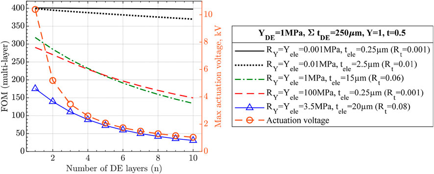
FIGURE 7. Actuation performance of multilayer unimorph DEA with various number of layers and electrodes. Cumulative thickness of all DE layers, passive layer thickness, and modulus for both DE and passive layers are fixed to demonstrate the reduced actuation voltage and the stiffening effect of electrodes for multilayer unimorph DEAs.
2.2 Elastomer material selection
Selecting a dielectric material with an appropriate combination of electromechanical, handling, and manufacturability properties is crucial for actuators’ fabrication, performance, and application. Electromechanical properties for which the mixed silicone compositions were characterized include dielectric permittivity, breakdown strength, and Young’s modulus, which are later used in material selection through the derived FOMs and for modeling UDEA.
2.2.1 Elastomer manufacturability and handling
First, material properties related to actuators’ fabrication and application are investigated for the mixed silicone compositions. As discussed in Introduction, viscosity is a parameter of uncured polymers that dominantly drives their printability through different techniques. For two-component RT cured polymers, such as Sylgard 182, 184, and 186, viscosity gradually increases once an elastomer base is mixed with its curing agent. For fabrication and printing process, it means that there is a limitation in terms of time within which material can be used. Often, manufacturers provide a materials’ handling time within which viscosity does not interfere with manufacturing processes, e.g., the time within which viscosity doubles. However, the definition of handling time can be different and is too generalized for various manufacturing processes. During different printing processes, material curing can be affected differently and locally, e.g., by the presence of a heating bed, material experiencing various shear strain rates, etc. Therefore, viscosity of the silicones studied in this work is measured through two tests. The first test is a standard procedure to measure viscosity of liquids and is used to study the changes in viscosity during curing, which can be used to analyze materials’ manufacturability for different fabrication techniques. Considering the above together with handling and curing times of the silicones, the test aimed to investigate material viscous behavior for up to 12 h after the mixing process to simulate daytime usage of the material. The second test is performed to study the viscosity change effect during curing on contact dispensing 3D printing process.
The first viscosity test resulted in Figure 8 that demonstrates the change in dynamic viscosities of the materials with curing time, which can be called viscosity-time profiles. Lower initial viscosity and its steeper increase during the first fifteen to 30 minutes are attributed to the viscous heating of the silicones during the mixing process. Besides the initial region, all curves demonstrated monotonically growing viscosity and a clear exponential behavior was noticed for the fast-curing Sylgard 184 and 186 within the first 12 h.
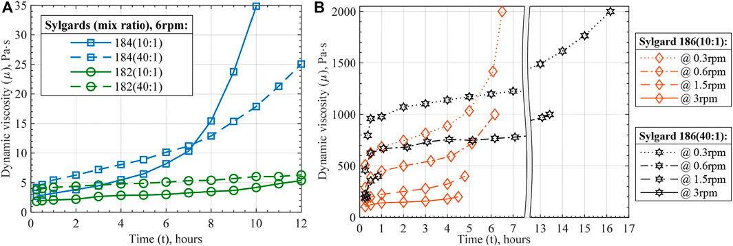
FIGURE 8. Viscosity-time profiles of the prepared silicones: (A) Sylgard 182 and 184, (B) Sylgard 186 at various viscometer revolutions per minute (rpm). The shown data points at each time instance represent average values of three to five measurements with the standard deviation of less than 1%.
Common for all three silicones, 40:1 ratio compositions showed higher initial viscosity. This agrees with the manufacturer’s data as higher viscosities are reported for elastomer bases than for mixed silicones. Therefore, higher content of elastomer base in 40:1 ratio composition results in a higher viscosity of the material right after the mixing. The second common characteristic is that silicones mixed in a 40:1 ratio increase their viscosity at slower rates than their 10:1 compositions. The slower rate of curing generally provides more handling time within which the materials can be processed. Nevertheless, within the 12-h study window, mixing in 40:1 ratio considerably affected the curing of Sylgard 184 and 186, but not 182. That is explained by the low rate of curing of Sylgard 182 mixed in 10:1 ratio.
Besides obtaining viscosity-curing characteristics of the mixed silicones composition, silicones' shear strain rate dependence was studied. It was noticed during the tests that Sylgard 182 and 184 viscosities have little dependence on shear strain rate. Meanwhile, Sylgard 186 demonstrated highly non-Newtonian pseudoplastic behavior (Figure 8B). Furthermore, a considerable thinning of Sylgard 186 at higher strain rates suggests that 3D printing it at higher rates eases the process wherever high viscosity reaches the equipment limitation. Particularly, the maximum strain rate was estimated to be about 0.27 1/s for 3 rpm viscometer speed and 95 1/s during the printing process of Sylgard 182 with the settings used in this work (Taylor, 1923; White and Majdalani, 2021). Lastly, the data presented in Figure 8 was used to interpolate viscosity-time functions of the Sylgard silicone compositions as for the Newtonian fluid for Sylgard 182 and 184, and the power-law fluid for Sylgard 186 (Table 2).
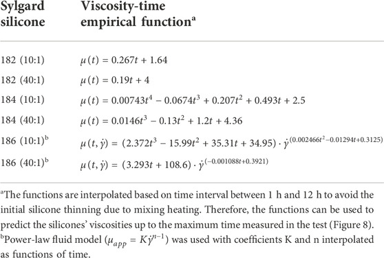
TABLE 2. Interpolated viscosity-time functions of Sylgard silicone compositions.
The second viscosity test was conducted by printing a line pattern with time intervals until the process was interfered by the silicone polymerization (Supplementary Figure S9). The same equipment and settings were used for the test as for printing UDEAs. By observing the defects of the printed lines, particularly the dripping along the printed lines, practical handling times for the mixed silicones when printing through contact dispensing can be estimated (Table 3). The printing test results show that all 40:1 silicone compositions extended their handling time compared to the 10:1 compositions despite having larger viscosity as per the viscometer testing. The discrepancy between actual handling time and potential predictions based on the measured viscosity, can come from various manufacturing factors, e.g., the difference in strain rates and correspondingly viscosity, viscous heating, etc.
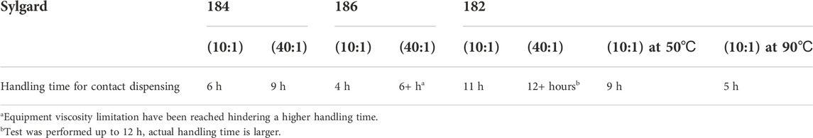
TABLE 3. Empirical handling time values various compositions of Sylgard silicones for contact dispensing.
In addition, handling time of Sylgard 182 (10:1) was evaluated when printing on a heating bed at elevated temperature, and the dispensing head was raised 20 mm about the heating bed Printing at elevated temperatures showed a considerable reduction in handling time. Nevertheless, it can be used for slow-curing silicones like Sylgard 182 to speed up the printing process and minimize or completely avoid intermediate curing cycles between printing the layers.
2.2.2 Elastomer electromechanical characterization
This section presents characterization of prepared silicone compositions for mechanical and dielectric properties relevant to DEA actuation. Following the discussion of each property, all the major values can be found in Table 4.
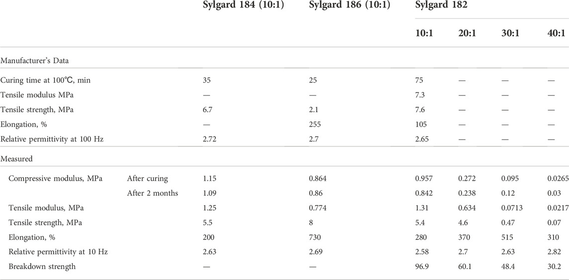
TABLE 4. Electromechanical characterization of the prepared PDMS compositions.
Lowering the stiffness of DEA materials is one of the approaches to increase actuation performance, which was performed through two methods in the present study. The first method was the non-standard ratio mixing applied for PDMS Sylgard 182. The second method was curing the material at a temperature lower than stated in the manufacturer’s material data sheet but for a longer time (90
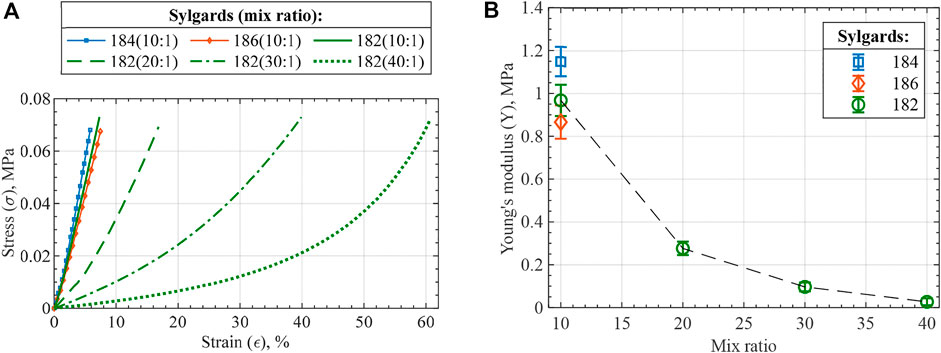
FIGURE 9. Compression test results of the prepared PDMS compositions in the form of (A) stress-strain curves and (B) Young’s modulus. The stiffness analysis of the silicones is valid at a low strain range, e.g., 0%–10%, for the performed compressive test, since the stiffening of higher mix ratio compositions is largely due to cross-section expansion.
While the silicones’ moduli are reduced, relative dielectric permittivity and dielectric breakdown strength are critical for the final actuator performance. According to the derived FOMs, relative permittivity is equally important as the modulus, while breakdown strength is squared in the FOM expressions. Thin films made of mixed silicone compositions were prepared and tested for the two dielectric properties. For Sylgard 182 samples mixed in different ratios, relative permittivity differed within the standard deviation value with a negligible ascending trend (Figure 10A). In addition to standard mix ratios, 40:1 ratio samples were tested for both Sylgard 184 and 186 to prove the minor effect of mix ratio on relative permittivity. All the relative permittivity values agree with the manufacturer’s values and show no dependency on frequency within 101–104 Hz range Opposite behavior was observed for the tested materials in the case of breakdown strength, as can be seen in Figure 10B. A considerable decrease in breakdown strength is apparent for larger mix ratios with a substantial property degradation between 10:1 and 20:1 mix ratios. Comparison of the obtained breakdown strength values with manufacturer’s data is complicated because the manufacturer’s values typically measured for AC voltage result in considerably smaller breakdown strength values. Nevertheless, the measured breakdown strength of 10:1 Sylgard 182 is close to similar materials across the literature (Vaicekauskaite et al., 2019; Sikulskyi et al., 2021).
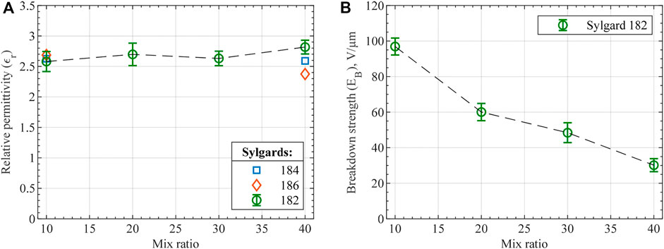
FIGURE 10. (A) Relative dielectric permittivity and (B) breakdown strength of the tested silicones. Each data point represents the average value of 5 measurements for relative permittivity and 10 measurements for breakdown strength with error bars demonstrating the standard deviation. shows Weibull probability plot for the measured breakdown strength of Sylgard 182 mix compositions.
2.2.3 UDEA design optimization
FOM is calculated for the actuator designs made of characterized materials. One option is to make both DE and passive layers of DEA out of the same mix ratio of Sylgard 182 composition. Figure 11A demonstrates the performance of the such actuator. If electrode stiffness is neglected, then the performance of the actuator increases as it is made of a more compliant Sylgard 182 composition as determined through FOM (no electrodes). However, as electrode stiffness is accounted for, the highest actuator performance can occur at silicone composition different from the most compliant one or even at the standard 10:1 mix ratio (as for the electrode used in this study).
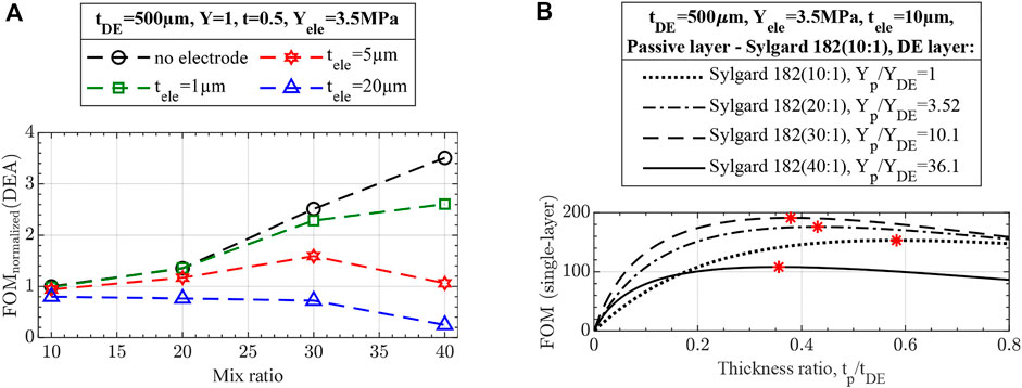
FIGURE 11. Performance of unimorph actuators through the FOM (single-layer) with (A) DE and passive layer sharing the same Sylgard 182 silicone mix ratio and various electrode thicknesses and (B) passive layer made of Sylgard 182 (10:1) ratio, various DE layers, and thinner 10 µm electrodes. Thinner electrodes were selected for the final verification not to compromise the performance enhancement of softened materials. DE layer thickness was increased to 500 µm to compensate for more compliant materials and prevent actuators’ excessive bending under their weight.
The second design approach is a combination of mix ratios. For instance, the passive layer can be fabricated with the standard 10:1 ratio of Sylgard 182, providing a thinner and stiffer passive layer, while various mixing ratios can be evaluated as DE layers. Figure 11B shows the design plot with variable DE layer materials, passive layer thickness, and fixed electrodes used in this study. As the figure shows, the actuator with the DE layer made of 30:1 mix ratio Sylgard 182 can achieve the highest performance of about 2.5 times larger than the optimized design for the actuator entirely made of 10:1 mix ratio silicone.
2.2.4 Actuation of 3D printed optimized UDEAs
This section presents the actuation of two single-layer UDEA designs selected based on Figure 11. The first actuator was the optimum design that was completely fabricated with Sylgard 182 (10:1) and served to validate the derived FOM for single-layer UDEA (Eq. 16). The second design was the optimized design with the passive layer fabricated with Sylgard 182 (10:1) but the DE layer made of Sylgard 182 (30:1) for achieving a higher curvature through the mixed elastomer compositions. Figure 12 demonstrates layout structure, appearance after fabrication, and actuation in the cantilever mode of both actuator designs. The design features, test results, and their comparison with analytical values are shown in Table 5. As the table shows, layers’ thicknesses of both actuators deviate from the designed values. However, the passive to DE layer thickness ratio
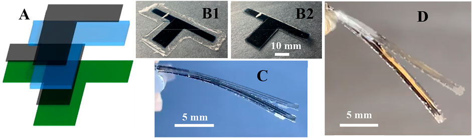
FIGURE 12. Single-layer unimorph DEA (A) layout, (B1) after printing and peeling off from the printing bed, (B2) after trimming and leaving some isolation material on the edges; bending of (C) design one due to weight only and at 9.8 kV (22.2 V/μm) applied and (D) design two due to weight only and at 6.4 kV (12.8 V/μm) applied.
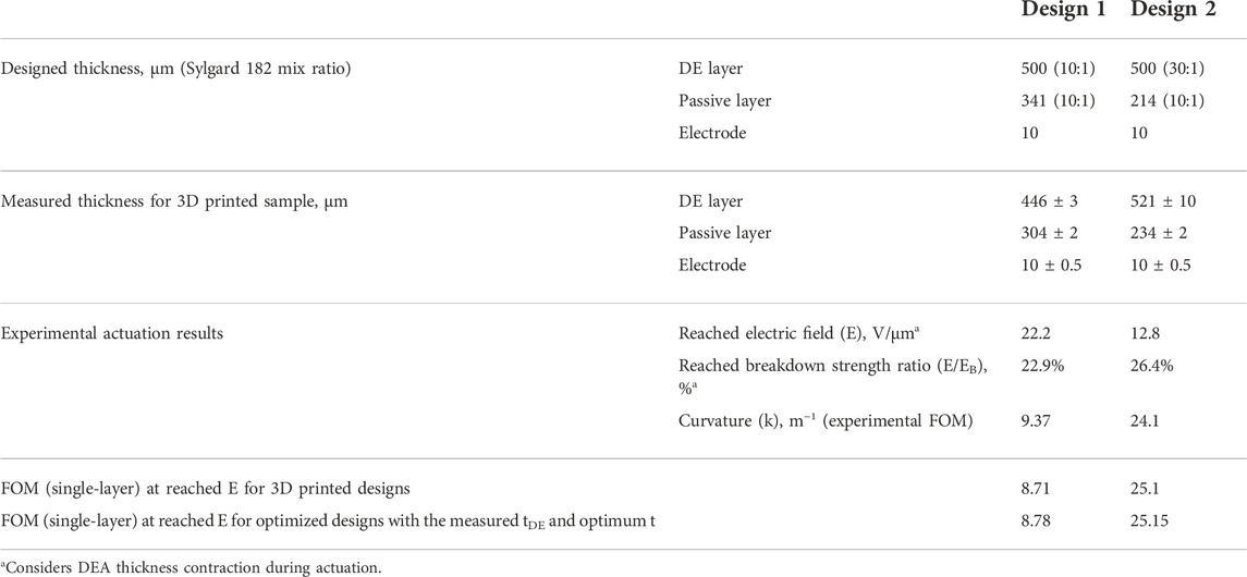
TABLE 5. Design, experimental, and analytical performance of optimized single-layer UDEA.
3 Experimental setup
All material handling, preparation, and characterization, as well as actuator 3D printing and testing, were performed in the laboratory air environment with a temperature of 22 ± 1
3.1 Materials
• PDMS elastomers: Sylgard 182 (Dow Inc., Midland, MI, United States, part #2065657), Sylgard 184 (Dow Inc., Midland, MI, United States, part #4019862), and Sylgard 186 (Dow Inc., Midland, MI, United States, part #2099551) are two-component temperature-cured silicones that were mixed in various ratios and tested for dielectric elastomer application and handling characteristics.
• PEDOT:PSS conductive polymer 1.1 wt.% aqueous solution (MilliporeSigma, Burlington, MA, United States, part #739332) was used as a conductive component of prepared electrode material for DEA electrodes.
• Triton X-100 plasticizer (MilliporeSigma, Burlington, MA, United States, part #X100) was used to soften PEDOT:PSS and reach sufficient compliance for the final DEA electrodes.
• Polyacrylic acid 35 wt% aqueous solution (MilliporeSigma, Burlington, MA, United States, part #416002) was used as a water soluble component of the sacrificial layer to ease the release process for thin 3D printed actuators from the printing substrate.
• Isopropanol (M.G. Chemicals Ltd., Burlington, ON, Canada, part #824) was used to further dissolve polyacrylic acid and achieve a faster evaporation rate (drying) of the sacrificial layer.
3.2 Material preparation
For each prepared silicone composition, the elastomer base (Part A) and curing agent (Part B) were added to the mixing cup and measured on scale to the desired weight ratio. The cup was then closed and placed into the planetary mixer THINKY ARM-310 (Laguna Hills, CA, United States) where mixing and simultaneous degassing were performed for 1 min at 2000 rpm for Sylgard 182 and 184. For Sylgard 186, an additional degassing procedure was applied due to the high viscosity of the silicone. After the initial 1-min mixing in the planetary mixer, the cup with the silicone was placed in the vacuum oven where −730 mmHg were applied for 5 min. Once the material was casted or applicated depending on the test, curing was performed at 90
For electrode material, PEDOT:PSS aqueous solution was mixed with Triton X-100 plasticizer in a ratio such that upon water evaporation, electrode consisted of 15 wt.% of PEDOT:PSS and 85 wt.% Triton X-100 (Sikulskyi, 2021). Mixing was performed with the planetary mixer THINKY ARM-310 once the materials reached a room temperature after taking them out of a fridge. The mixing cycle consisted of three steps of 5-2-5 min with the corresponding speed of 1200-2000-1200 rpm.
3.3 Material characterization
Viscosity-time profile test. Silicones were mixed and left in 150 ml plastic cups. Digital rotary viscometer NDJ-8S (KEYU, China) was used to measure the viscosity of the silicones. Switchable rotors were attached through a universal joint to the load cell of the viscometer on one end and submerged into the silicone in the cup on the other end. Rotor speed in revolution per minute (rpm) was selected according to the material viscosity and used rotor. Rotor 3 was used for Sylgards 182 and 184, and rotor 4 was used for Sylgard 186. Viscosity was measured until the limit for a specific rotor and rotational speed was reached. Curing time was counted from the moment the materials are placed in the mixer and the first measurement of the viscosity was performed at 15 min after the mixing process.
Dielectric permittivity test. The permittivity of the material samples was calculated based on measured capacitance
Breakdown strength test. The dielectric strength of prepared thin (100–150 µm) films was measured with a high-voltage amplifier TREK 20/20CH-S (Denver, CO, United States) by the slow rate-of-rise method according to ASTM D149. Considering the statistical nature of the breakdown, its analysis was performed based on twenty measurements for each material composition of prepared films.
Mechanical tests. Three tests were performed to evaluate mechanical behavior of the mixed materials. Compressive test was performed using universal test machine AMETEK CS225 (Berwyn, PA, United States) with a 5 kg load cell and compression plates G1009 on the standard ASTM D575 cylindrical specimens with a diameter of 28.2 ± 0.28 mm and height of 12.1 ± 0.8 mm (ASTM, 2018). A low compressive rate of 12 mm/min (about 100% of stain per minute) was chosen to accurately measure material’s stiffness at low strain. Compressive Young’s modulus was calculated as the slope for a relatively large strain range (0% and 5%) due to data linearity in this range and to compensate for sample imperfect shape. To prepare the specimens, mixed silicones were casted in DLP 3D printed resin molds placed on top of a PET film and cured as described above.
Second mechanical testing was evaluation of compressive behavior using Nanoindenter Bruker Hysitron TI-980 (Billerica, MA, United States). Small cylindrical samples of prepared silicones were used in the test. The force of 100 µN was applied to the 10:1 mix ratio of all three silicones, while 50 µN was applied to the 20:1 mix ratio of Sylgard 20:1 and higher mix ratios were too soft to be measured with the equipment.
Additionally, tensile test was performed to mainly evaluate effects of mix ration on stretchability and strain stiffening of silicones. Same universal test machine was used with a 1 kg load cell and wedge grip Mark-10 G1061-3 with rubber jaw faces on dogbone ASTM D412 Type D specimens cut from the 300 µm thick films with an extension rate of 40 mm/min (about 100% of strain per minute). For the tensile test, Young’s modulus was determined as the slope on the stress-strain curves between 0% and 1%.
3.4 3D printing of unimorph DEA
The actuators were printed using HYREL 30M (HYREL 3D, Norcross, GA, United States) printer with dispensing heads SDS-10, where elastomers and electrode material were manually loaded into the syringes after mixing and degassing. Before printing the passive layer, a glass substrate was coated with the sacrificial layer (5 wt.% polyacrylic acid, 11 wt.% water, 84 wt.% isopropanol) to ease release of thin actuators from the printing glass substrate. Before printing each electrode layer, a previously printed and cured elastomer layer underwent a plasma surface treatment with the corona surface treater ETP MODEL BD-20 (ElectroTechnic Products Inc, Chicago, IL, United States, part #12011A). To facilitate printing process, the printing bed temperature was maintained at 50
3.5 Actuation testing
Fabricated actuators were cantilevered on one side where electrodes were attached to the high-voltage amplifier TREK 20/20CH-S. A smartphone camera was used to record the deformation of the actuators as the applied voltage was gradually and controllably increased. A custom MATLAB code was used with the recorded videos to capture actuators’ deformed shape at various values of applied voltage. The captured data was then transformed into curvature vs. electric field.
4 Conclusion
This study presented numerous accomplished objectives for the development of UDEAs. First, based on the derived and numerically validated analytical model, FOMs were obtained to clearly illustrate the role of each actuator layer and specific design feature effects:
• Total actuator thickness is amongst the most critical parameters to drive UDEA deformation capabilities.
• For the fixed total thickness of DEA and compliant electrode, different material combinations with optimized thickness ratios result in the same actuation performance in terms of deformation. For electrodes with finite stiffness, UDEA performance can be modified in a relatively small range based on the selected material combination of the passive and DE layers and optimized thickness ratios.
• Considering DEA 3D printing process peculiarities, fixing DE thickness rather than total thickness was recommended while optimizing the passive layer. Furthermore, different material-thickness optimum ratios were emphasized for actuators with fixed total and DE thicknesses.
• Effects of electrode thickness and modulus were demonstrated for single-layer and multilayer UDEA.
• Multilayer UDEA requires thinner DE layers to maintain actuation performance at a lower voltage (equivalent electric field). Consequently, having thin electrodes becomes even more critical to maintaining actuator performance.
Common and promising elastomer compositions were prepared, modified by varying their mixing ratios, and characterized for both actuation performance and printability objectives. For example, a considerable improvement in printing/handling time was achieved for fast-curing PDMS like Sylgard 184 and Sylgard 186 when mixed at a 40:1 ratio. Alternatively, certain mix ratios of PDMS Sylgard 182 improved their actuation performance according to the derived FOMs while already having an extensive handling/printing time.
Finally, the derived FOMs were used to obtain two different optimized UDEA designs, which were tested to validate the FOMs and demonstrate higher actuation performance of the optimized actuator fabricated with various elastomer compositions.
The future work can include considering large deflection in analytical model to accurately predict of UDEA deformation and modeling UDEA as a plate to model two-dimensional UDEA designs.
Data availability statement
The original contributions presented in the study are included in the article/Supplementary Material, further inquiries can be directed to the corresponding author.
Author contributions
SS conceptualization, methodology, experimentation, analysis, and writing-reviewing-editing. ZR conceptualization, methodology, experimentation, analysis, and writing-reviewing-editing. DM conceptualization, methodology, experimentation, and writing-reviewing-editing. AH conceptualization, methodology, and experimentation. RS experimentation and writing-reviewing-editing. DK conceptualization, methodology, and writing-reviewing-editing.
Conflict of interest
The authors declare that the research was conducted in the absence of any commercial or financial relationships that could be construed as a potential conflict of interest.
Publisher’s note
All claims expressed in this article are solely those of the authors and do not necessarily represent those of their affiliated organizations, or those of the publisher, the editors and the reviewers. Any product that may be evaluated in this article, or claim that may be made by its manufacturer, is not guaranteed or endorsed by the publisher.
Supplementary material
The Supplementary Material for this article can be found online at: https://www.frontiersin.org/articles/10.3389/frobt.2022.1034914/full#supplementary-material
References
Araromi, O. A., and Burgess, S. C. (2012). A finite element approach for modelling multilayer unimorph dielectric elastomer actuators with inhomogeneous layer geometry. Smart Mat. Struct. 21 (3), 032001. doi:10.1088/0964-1726/21/3/032001
ASTM (2018). D575-91 standard test methods for rubber properties in compression. West Conshohocken, PA: ASTM, 4.
Ballas, R. (2007). Piezoelectric multilayer beam bending actuators static and dynamic behavior and aspects of sensor integration. 978-3-540-32641-0.
Carpi, F., Anderson, I., Bauer, S., Frediani, G., Gallone, G., Gei, M., et al. (2015). Standards for dielectric elastomer transducers. Smart Mat. Struct. 24 (10), 105025. doi:10.1088/0964-1726/24/10/105025
Chen, A. Y., Pegg, E., Jin, Z., and Gu, G. X. (2021). 4D printing of electroactive materials. Adv. Intell. Syst. 3 (12), 2100019. doi:10.1002/aisy.202100019
Chen, Y., Zhao, H., Mao, J., Chirarattananon, P., Helbling, E. F., Hyun, N. s. P., et al. (2019). Controlled flight of a microrobot powered by soft artificial muscles. Nature 575, 324–329. doi:10.1038/s41586-019-1737-7
Chortos, A., Hajiesmaili, E., Morales, J., Clarke, D. R., and Lewis, J. A. (2020). 3D printing of interdigitated dielectric elastomer actuators. Adv. Funct. Mat. 30 (1), 1907375. doi:10.1002/adfm.201907375
Chortos, A., Mao, J., Mueller, J., Hajiesmaili, E., Lewis, J. A., and Clarke, D. R. (2021). Printing reconfigurable bundles of dielectric elastomer fibers. Adv. Funct. Mat. 31 (22), 2010643. doi:10.1002/adfm.202010643
Duduta, M., Hajiesmaili, E., Zhao, H., Wood, R. J., and Clarke, D. R. (2019). Realizing the potential of dielectric elastomer artificial muscles. Proc. Natl. Acad. Sci. U. S. A. 116, 2476–2481. doi:10.1073/pnas.1815053116
Duduta, M., Wood, R., and Clarke, D. (2016). Multilayer Dielectric Elastomers for Fast, 28. Wiley–Hoboken, NJ: Programmable Actuation without Prestretch. Advanced Materials.
Gareis, M., and Maas, J. (2021). Multilayer dielectric elastomer unimorph actuators for self-folding shape-shifting surfaces, 11587. SPIE Smart Structures + Nondestructive EvaluationSPIE. Online event.
Haghiashtiani, G., Habtour, E., Park, S. H., Gardea, F., and McAlpine, M. C. (2018). 3D printed electrically-driven soft actuators. Extreme Mech. Lett. 21, 1–8. doi:10.1016/j.eml.2018.02.002
Hajiesmaili, E., and Clarke, D. R. (2021). Dielectric elastomer actuators. J. Appl. Phys. 129 (15), 151102. doi:10.1063/5.0043959
Jiang, L., Wang, Y., Wang, X., Ning, F., Wen, S., Zhou, Y., et al. (2021). Electrohydrodynamic printing of a dielectric elastomer actuator and its application in tunable lenses. Compos. Part A Appl. Sci. Manuf. 147, 106461. doi:10.1016/j.compositesa.2021.106461
Kadooka, K., Imamura, H., and Taya, M. (2016). Experimentally verified model of viscoelastic behavior of multilayer unimorph dielectric elastomer actuators. Smart Mat. Struct. 25 (10), 105028. doi:10.1088/0964-1726/25/10/105028
Kadooka, K. (2017). “Modeling, processing, and characterization of dielectric elastomer actuators and sensors,” in Mechanical engineering (Seattle, WA: University of Washington).
Kim, D., and Sikulskyi, S. (2022). “2 - 4D-printed dielectric elastomer soft robots: Modeling and fabrications,” in Smart materials in additive manufacturing, volume 1: 4D printing principles and fabrication. Editors M. Bodaghi, and A. Zolfagharian (Elsevier), 19–54.
Lau, G.-K., Goh, S. C.-K., and Shiau, L.-L. (2011). Dielectric elastomer unimorph using flexible electrodes of electrolessly deposited (ELD) silver. Sensors Actuators A Phys. 169 (1), 234–241. doi:10.1016/j.sna.2011.04.037
Li, J., Wu, S., Zhang, W., Ma, K., and Jin, G. (2022). 3D printing of silicone elastomers for soft actuators. Actuators 11 (7), 200. doi:10.3390/act11070200
McKay, T., Calius, E., and Anderson, I. (2009). “The dielectric constant of 3M VHB: A parameter in dispute,” in Proc. Of SPIE, electroactive polymer actuators and devices.
Naniz, M. A., Askari, M., Zolfagharian, A., and Bodaghi, M. (2022). “6 - 4D bioprinting: Fabrication approaches and biomedical applications,” in Smart materials in additive manufacturing. Editors M. Bodaghi, and A. Zolfagharian (Elsevier), 193–229.
Pelrine, R. E., Kornbluh, R. D., and Joseph, J. P. (1998). Electrostriction of polymer dielectrics with compliant electrodes as a means of actuation. Sensors Actuators A Phys. 64 (1), 77–85. doi:10.1016/s0924-4247(97)01657-9
Pu, J., Meng, Y., Xie, Z., Peng, Z., Wu, J., Shi, Y., et al. (2022). A unimorph nanocomposite dielectric elastomer for large out-of-plane actuation. Sci. Adv. 8 (9), 6200. doi:10.1126/sciadv.abm6200
Regis, J. E., Renteria, A., Hall, S. E., Hassan, M. S., Marquez, C., and Lin, Y. (2021). Recent trends and innovation in additive manufacturing of soft functional materials. Materials 14 (16), 4521. doi:10.3390/ma14164521
Schlatter, S., Grasso, G., Rosset, S., and Shea, H. (2020). Inkjet printing of complex soft machines with densely integrated electrostatic actuators. Adv. Intell. Syst. 2, 2000136. n/a(n. doi:10.1002/aisy.202000136
Shintake, J., Ichige, D., Kanno, R., Nagai, T., and Shimizu, K. (2021). Monolithic stacked dielectric elastomer actuators. Front. Robot. AI 8, 714332. doi:10.3389/frobt.2021.714332
Sikulskyi, S. (2021). “Additively manufactured dielectric elastomer actuators: Development and performance enhancement,” in Aerospace engineering (Daytona Beach, FL: Embry-Riddle Aeronautical University), 184.
Sikulskyi, S., Zefu, R., Srinivasaraghavan Govindarajan, R., Mekonnen, D., Madiyar, F., and Kim, D. (2022). Additively manufactured unimorph dielectric elastomer actuators with ferroelectric particles for enhanced low-voltage actuation, 12042. Long Beach, CA: SPIE Smart Structures + Nondestructive EvaluationSPIE.
Sikulskyi, S., Yu, S. L., Rojas-Nastrucci, E., Park, J., and Kim, D. (2020). “Soft and printable electrodes for flexible elastomer actuators,” in Proc. Of SPIE electroactive polymer actuators and devices (EAPAD) XXII (SPIE). Online event.
Sikulskyi, S., Mekonnen, D. T., El Atrache, A., Divo, E., and Kim, D. (2021). Effects of ferroelectric fillers on composite dielectric elastomer actuator. Actuators 10 (7), 137. doi:10.3390/act10070137
Taylor, G. I. (1923). VIII. Stability of a viscous liquid contained between two rotating cylinders. Philosophical Trans. R. Soc. Lond. Ser. A, Contain. Pap. a Math. or Phys. Character 223 (605-615), 289–343.
Ugural, A. C. (2017). Plates and shells: Theory and analysis. Fourth Edition. Boca Raton, FL: CRC Press.
Vaicekauskaite, J., Mazurek, P., Vudayagiri, S., and Ladegaard Skov, A. (2019). “Silicone elastomer map: Design the ideal elastomer,” in SPIE smart structures + nondestructive evaluation (Denver, CO: SPIE).
Wang, Q.-M., and Cross, L. E. (1998). Performance analysis of piezoelectric cantilever bending actuators. Ferroelectrics 215 (1), 187–213. doi:10.1080/00150199808229562
Keywords: unimorph dielectric elastomer actuator (UDEA), bending actuator, modeling, figure of merit, material selection, 3D printing, viscosity, manufacturability
Citation: Sikulskyi S, Ren Z, Mekonnen DT, Holyoak A, Srinivasaraghavan Govindarajan R and Kim D (2022) Additively manufactured unimorph dielectric elastomer actuators: Design, materials, and fabrication. Front. Robot. AI 9:1034914. doi: 10.3389/frobt.2022.1034914
Received: 02 September 2022; Accepted: 31 October 2022;
Published: 16 December 2022.
Edited by:
Ali Zolfagharian, Deakin University, AustraliaReviewed by:
Milan Shrestha, Nanyang Technological University, SingaporeAnand Kumar Mishra, Cornell University, United States
Copyright © 2022 Sikulskyi, Ren, Mekonnen, Holyoak, Srinivasaraghavan Govindarajan and Kim. This is an open-access article distributed under the terms of the Creative Commons Attribution License (CC BY). The use, distribution or reproduction in other forums is permitted, provided the original author(s) and the copyright owner(s) are credited and that the original publication in this journal is cited, in accordance with accepted academic practice. No use, distribution or reproduction is permitted which does not comply with these terms.
*Correspondence: Daewon Kim, a2ltZDNjQGVyYXUuZWR1