 Miharu Kojima1
 Tomomichi Sugihara2*
- 1Department of Adaptive Machine Systems, Graduate School of Engineering, Osaka University, Suita, Japan
- 2OMRON Corporation, Tokyo, Japan
An explicit mathematical form of a human’s step-and-brake controller is identified through motion measurement of the human subject. The controller was originally designed for biped robots based on the reduced-order dynamics and the model predictive control scheme with the terminal capturability condition, and is compatible with both stand-still and stepping motions. The minimal number of parameters facilitates the identification from measured trajectories of the center of mass and the zero-moment point of the human subject. In spite of the minimality, the result only suited the human’s behaviors well with slight modifications of the model by taking direction-dependency of the natural falling speed and the inertial torque about the center of mass into account. Furthermore, the parameters are successfully identified even from the first half of motion sequence, which means that the proposed method is available in designing on-the-fly systems to evaluate balancing abilities of humans and to assist balances of humans in walking.
Introduction
Biped locomotion is one of the fundamental functions of humans. It is valuable to understand how skillful behaviors for locomotion are synthesized not only from a scientific but also a practical viewpoint as it suggests efficient methods for medical diagnoses, rehabilitations, assistive system designs, for example. While lots of knowledge about how human body parts contribute to walking has been accumulated particularly in the fields of physiology and clinical medicine, it is also necessary to know how those parts are coordinated into the whole-body motion in order to properly diagnose and effectively aid humans’ locomotion abilities. In this regard, it has been demanded to find a plausible mathematical model of the humans’ locomotion controller (Cavagna and Margaria, 1966; Yamashita et al., 1972; Alexander, 1976; McMahon, 1984; Ren et al., 2006; Schmitthenner and Martin, 2021), which is still challenging.
Many studies (Taga, 1995; Hase and Yamazaki, 1998; Xiang et al., 2011; Shachykov et al., 2019) to reproduce locomotive behaviors on a multi-link neuro-musculoskeletal system model in computer simulations have been made. When aiming to describe the humans’ control mechanism in a comprehensible manner rather than to simulate biological behaviors precisely, it is reasonable to focus on the reduced dynamics of the whole-body. The center of mass (COM) is a point into which effective inertia of the body is condensed, and hence, has been studied in many works (Whittle, 1997; Lee and Farley, 1998; Hof, 2008). It is also known (Mitobe et al., 2000) that the macroscopic dynamics of the overall anthropomorphic system can be represented based on the relationship between the COM and the center of pressure (COP), which is also called the zero-moment point (ZMP) (Vukobratović and Stepanenko, 1972) in the field of robotics.
Even if we only focus on the reduced dynamics, it is not easy to understand the mechanisms of the behavior to carry a foot from the current place to another since it is accompanied with a complex coordination of the COM and the ZMP. A dynamic loading and unloading on the both soles and a smooth transition of the pivot foot are required during the process; while a foot to step should be unloaded in order to lift off the ground, the same foot initially has to be loaded in order to accelerate the COM appropriately.
The goal of this work is to find a mathematical model of a controller of a human’s step-and-brake motion as the minimum motion unit of the above process. The authors (Sugihara et al., 2022) have learned that control techniques developed for biped robots potentially explain the humans’ control schemes because of the morphologic, and accordingly, dynamical similarity between humanoid robots and humans. Among a number of controllers proposed in the field so far, Sugihara et al.’s method (Sugihara and Yamamoto, 2017; Yamamoto and Sugihara, 2020) was picked up as the primary candidate of the model due to its minimal property in a sense that it is derived from the minimal conditions to stabilize a biped robot from the minimal number of parameters and state variables based on the terminal capturability (Pratt et al., 2006; Koolen et al., 2012). Parameter identifications of the model were conducted from measured motion trajectories of a human subject. Though the authors predicted at first that the model would be only a starting point and need a lot of improvements to fill in the gaps from the actual behavior of a human, the model surprisingly fitted it with slight modifications, which was a consideration of direction-dependent time-constant of natural falling and the inertial torque about the COM. A contribution of this work over the previous researches which focused on the capturability during the stance (Hof, 2008) and that predicted landing positions of feet (Aftab et al., 2012) is that a model of the feedback controller that reproduces the overall dynamic stepping motion process was identified in a mathematically explicit form in it. We also note that our result has been already utilized in another work (Yoshikawa, 2022).
An early version of this work was presented at the eighth IEEE RAS/EMBS International Conference on Biomedical Robotics and Biomechatronics (Kojima and Sugihara, 2020). A clear modification in this paper from the version is at the last part of Section 5. We newly confirmed that the control parameters could be estimated only from the first half movement before completing the action. It means that the model is available in designing on-the-fly systems, for example, to evaluate balancing abilities of humans and to assist balances of humans in walking.
COM-ZMP Model for Human Dynamics
The COM-ZMP model (Mitobe et al., 2000) is often employed in the field of humanoid robotics as a reduced-order representation of dynamics of the robot. This is also available for the human dynamics analysis. Let us consider a human’s motion on the sagittal plane as illustrated in Figure 1. Suppose both the vertical movement of the COM and the inertial torque about the COM are negligibly small. The equation of motion of the COM is represented as
where x and xZ are the longitudinal positions of the COM and the ZMP, respectively, z is the height of the COM with respect to the nominal ground, which is assumed to be constant, and g = 9.8 m/s2 is the acceleration due to the gravity. For the mathematical derivation, refer Sugihara and Morisawa (2020). The ZMP is naturally constrained within the supporting region due to the unilaterality of the contact forces as
where xZmin and xZmax are the rear and front ends of the supporting region in x-axis, respectively. We also assume that the human can gain a sufficient friction force from the ground, so that its limitation is not taken into account.

FIGURE 1. The COM-ZMP model for human dynamics in the sagittal plane. It is additionally assumed that the vertical movement of COM and the inertial torque about COM are negligibly small.
The COM-ZMP model is utilized in several contexts such as motion planning (Kajita et al., 2003; Nagasaka et al., 2004; Harada et al., 2006; Sugihara and Nakamura, 2009) and control (Mitobe et al., 2000; Sugihara et al., 2002; Morimoto et al., 2008; Sugihara, 2009). The authors (Sugihara et al., 2022) found that the COM-ZMP regulator (Sugihara, 2009) fairly models a standing stabilization behavior of a human through a system identification technique. Although it is not directly related with the step-and-brake control, it provides some relevant knowledge about the study in this paper. Hence, we summarize it here in order to deepen the following discussions.
The COM-ZMP regulator is a controller to stabilize the COM of a humanoid in stance, in which the desired ZMP dxZ is decided by a piecewise-linear feedback of the state of the COM as
where dx is the referential position of the COM and k1 and k2 are feedback gains. Note that this is equivalent with determining the desired net ground reaction force under the assumption that the COM keeps the constant height. Suppose the actual ZMP is manipulated so as to track the desired ZMP accurately, i.e., xZ = dxZ. The feedback system becomes piecewise-affine as
When the system poles in (S2) are − ζq1 and − ζq2, the following equation holds:
Figure 2 shows a typical example of a phase portrait of the system defined by Eq. 6 with
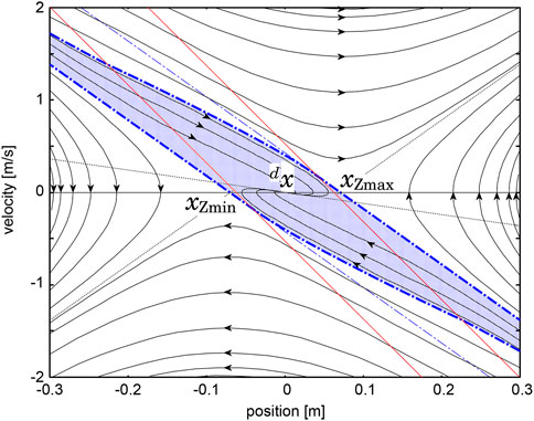
FIGURE 2. Theoretical phase portrait of the COM-ZMP regulator represented by Eqs 1, 3, 4 with
A human’s standing controller was identified from motion trajectories measured by an optical motion capture system under a hypothesis that the human’s behavior is modeled by Eq. 6. Figure 3 shows the result in the lateral plane, in which cyan points are samples of the measured trajectories and solid lines are trajectories of the identified dynamical system. Refer the original paper for the detail. The resemblance of Figures 2, 3 qualitatively supports the hypothesis. A quantitative analysis made in the original paper revealed a worth mentioning difference between them that the two asymptotic lines in (S1) and (S3) are not symmetric with respect to the axes, which means that the time-constant of natural falling motion depends on the direction. This characteristic is magnified in the longitudinal direction, and thus, will be reconsidered later.
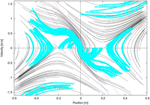
FIGURE 3. phase portrait of an identified COM-ZMP regulator from a human’s behavior in our previous work (Sugihara et al., 2022).
Measurement of Step-And-Brake Motions
Motion measurement experiments were conducted in order to observe movements of the COM, the ZMP and the feet during the step-and-brake motions. Figure 4 illustrates a set-up of the measurement system. 3D trajectories of 39 retroreflective markers attached on the subject’s body according to Figure 5 were measured at 240 Hz of the sampling rate by an optical motion capture system (VENUS3D; Nobby Tech. Ltd.) with 11 infrared cameras. At the same time, the reaction forces and torques from the ground were measured by force plates (TF-6090; Tech Gihan Inc.,). The forces exerted to each foot were separately measured by different plates. The trajectories of the ZMP were computed from the reaction forces and torques. The subject was a 23-year-old healthy female, who was 158 cm tall and weighed 48 kg. She was informed the objective and risk of the experiment and understood them in advance. In each trial, she initially took a standing posture, got her left-foot to step onto a location specified by tapes put on the force plates as depicted in the right side of Figure 4, and braked herself immediately after landing. The tapes were put in 25 ∼65 cm range from the initial position with 10 cm intervals. The stepping durations were controlled by a metronome at 100 bpm. The referential position of the COM to settle was not visually indicated, but the reaction forces on each foot were displayed in real-time in a monitor in front of the subject, which guided her to balance them and locate the COM at the middle of the both feet. Eight trajectories with respect to each designated location to step were collected. Hence, the total number of the trajectories was 40. The trajectories of the COM were estimated based on a standard mass-distribution model of Japanese adult females (Ae et al., 1992) that was scaled in accordance with the subject’s body proportion. Measurement noises were reduced by a second-order Butterworth filter with 5 Hz of cutoff frequency, which was tuned by trial and error. A history of velocity and acceleration of the COM were computed by the midpoint finite difference method.
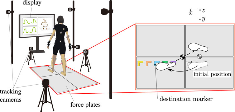
FIGURE 4. Set-up of the motion measurement system with 11 infrared cameras and 4 force plates. The foot-landing locations are specified by marker tapes put on the force plates.
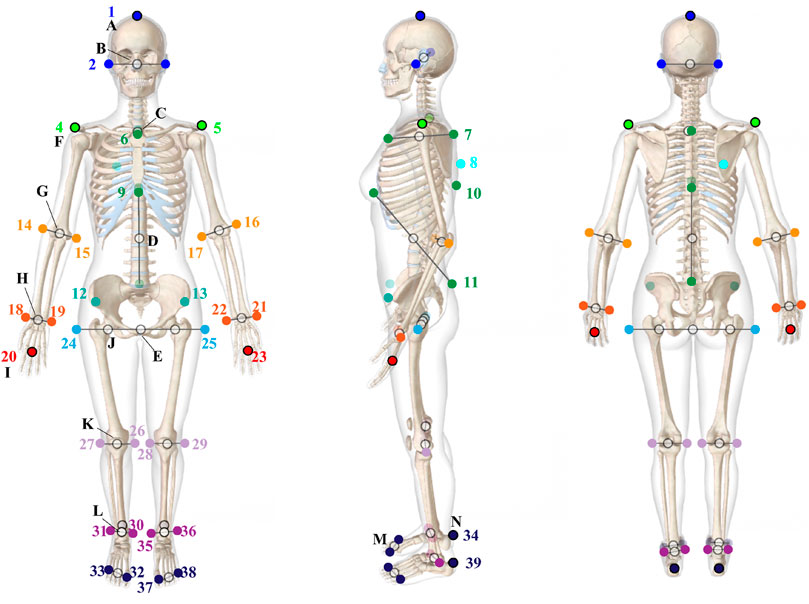
FIGURE 5. Definitions of 39 retroreflective markers attached on the subject’s body for the motion measurement.
A typical time series of motion is plotted in Figure 6. The black line around 1.1 s indicates the moment at which the reaction force to the stepping foot exceeded a threshold, and thus, the subject was thought to land her foot on the force plate. The trajectory is separated by the moment into two phases. Let us call the former the stepping phase and the latter the braking phase. While the COM moved smoothly from the initial to the final position over the phase transition, the ZMP presents a distinctive history in each phase. It was initially pulled back in order to accelerate the COM, gradually moved forward, and was finally saturated at the edge of the pivot foot in the stepping phase. In the braking phase, the ZMP went forward and overtook the COM to decelerate it immediately after landing, and brought it smoothly into the referential position. Finally, the COM and the ZMP converged to the same position.
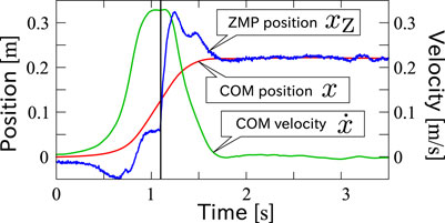
FIGURE 6. A typical time series of COM position (red line), COM velocity (green line) and ZMP (blue line) of step-and-brake motions. The black vertical line indicates the detected moment of foot-landing.
Figure 7 shows the measured motion trajectories collected in x-
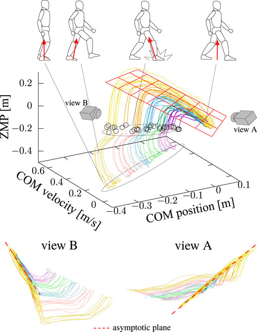
FIGURE 7. Collected trajectories of step-and-brake motions in x-
In order to investigate the above observation, standing stabilization motions in the sagittal plane were measured in accordance with the same protocol with the authors’ previous work (Sugihara et al., 2022). The subject took the final posture of the step-and-brake motion with 45 cm of the landing point from the initial position. The motion trajectories were obtained by perturbing her in stance as shown in Figure 8. It is confirmed that the behavior is modeled as a piecewise-linear system and the asymptotic lines (red chained lines) are not symmetric as well as the lateral standing measured in the previous work. The clustering technique proposed in (Sugihara et al., 2022) successfully divided the x-
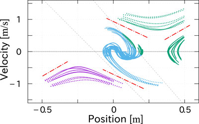
FIGURE 8. Trajectories of standing motions in x-
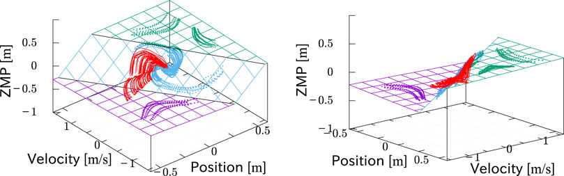
FIGURE 9. Trajectories of standing motions (cyan, green and purple) in x-
Mathematical Model of a Step-And-Brake Controller
The result in the previous section obviously showed that the piecewise-linear state feedback Eq. 5 does not fit the observed step-and-brake behavior, though the behavior finally converges to it. Among several candidates of the mathematical model of the controller, the authors focus on a biped robot control proposed by Sugihara et al. (Sugihara and Yamamoto, 2017; Yamamoto and Sugihara, 2020) and adopt it as the primary model because of its minimal property. To be minimal means that it is derived from the minimal conditions to continue the biped motion stably, namely, to confine the desired ZMP in the pivot sole and to guarantee the terminal capturability. It also requires the minimal number of state variables to feedback, which are position and velocity of the COM as well as the COM-ZMP regulator described in Section 2 — the acceleration of the COM is not referred unlike other conventional control schemes (Kajita et al., 2003; Herdt et al., 2010). Accordingly, the controller depends on the minimal number of parameters, which are the locations of the pivot foot, the desired position of the capture point and the motion duration. In spite of the above minimal formulation, it can achieve both the stepping and braking motions in a unified manner.
In the original work, the COM-ZMP model represented by Eq. 1 was assumed in order to derive the feedback law. This system with xZ ≡const. has two eigenvalues ζ (unstable) and − ζ (stable) with symmetric asymptotic directions
where T is the desired terminal time for landing or braking, t is the current time, xP is the location of the pivot foot, and dxC is the desired position of the capture point. The subjected equality condition other than Eq. 1 in the above means that the capturability condition (Pratt et al., 2006; Koolen et al., 2012) at the final time is satisfied. The problem (8) is analytically solved as
where
dxZ with the above control law asymptotically converges to xP. If dxC = xP, x also stably converges to xP. Otherwise, x is destabilized and diverges toward dxC. The former and latter lead to the braking and the stepping motions, respectively. Hence, the stepping and braking controls are switched only by unequalizing and equalizing xP and dxC, respectively. In addition, xCP also asymptotically converges to dxCP, which might explain the process in which the trajectories of the COM converges to a plane as shown in Figure 7.
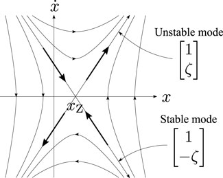
FIGURE 10. phase portrait of the system Eq. 1 with xZ ≡const. It has two eigenvalues ζ (unstable) and − ζ (stable) with symmetric asymptotic directions
On the other hand, the actual behavior of the human’s COM exhibits direction-dependent modes of falling as portrayed in Figure 8. Hence, we take this into account and employ the following modified equation of motion:
This system with xZ ≡const. has two eigenvalues ζ1 (unstable) and − ζ2 (stable) with asymmetric asymptotic directions
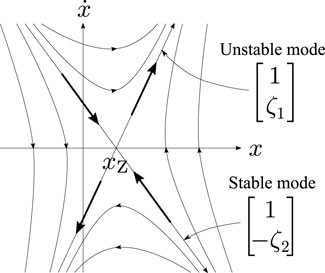
FIGURE 11. phase portrait of the system Eq. 12 with xZ ≡const. It has two eigenvalues ζ1 (unstable) and − ζ2 (stable) with asymmetric asymptotic directions
This is also analytically solved as
where xCP is redefined as
Result of Parameter Identification and Discussion
A system identification from the motion trajectories in Figure 7 was conducted based on Eq. 14 with a modification to take the effect of the inertial torque about the COM into account approximately as
where L is the angular momentum about the COM divided by the vertical ground reaction force and c is a constant coefficient. The parameters to be identified in the above equation are xP, dxC, ζ1, ζ2, c and T. Since the motion is separated into the stepping and braking phases, we have two corresponding sets of the above parameters. Thus, we distinguish them as xP1, dxC1, ζ11, ζ21, c1 and T1 for the stepping phase, and as xP2, dxC2, ζ12, ζ22, c2 and T2 for the braking phase, respectively. In order to simpify the problem to be solved, T1 and T2 were determined as the time when the measured reaction force and the measured acceleration of the COM exceeded the corresponding thresholds, respectively, in advance. Then, the remaining parameters were identified separately in each phase by solving the following least square minimization problem:
where * = 1 or 2, k is the discretized time index,
Δt is the sampling interval, and N* = T*/Δt. [k] denotes that the associated quantities were sampled at t = kΔt. The above problem was solved by the steepest descent method, where the gradient was numerically estimated by finite difference.
Figures 12, 13 present the trajectories of the ZMP of the motions with a stride of 45 cm based on Eqs 14, 16, respectively. The cyan lines in the figures are the measured trajectories, while the black lines were reproduced from the identified parameters. The figures show that Eq. 14 captures characteristics of the time profile of the ZMP and the identification accuracy in the braking phase after the foot-landing was improved due to the additional term in Eq. 16, while it is not much in the stepping phase. All the trajectories of x-
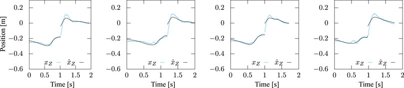
FIGURE 12. Measured and identified ZMP trajectories based on Eq. 14, in which the inertial torque about COM was ignored. Step stride was controlled to be 45 cm. While the latter reproduced the former well in the stepping phase, substantial errors are observed after landing.
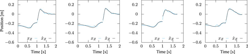
FIGURE 13. Measured and identified ZMP trajectories based on Eq. 16, in which the inertial torque about COM is taken into account. Step stride was controlled to be 45 cm. The latter reproduced the former well in both the stepping and braking phases.
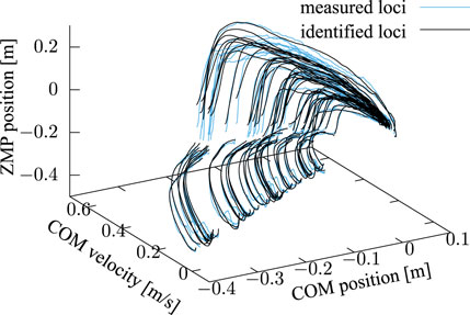
FIGURE 14. Trajectories of x-
Figure 15 shows the result of the identification of each parameter. In the left figure, the final position of the COM is reset to be the original point. The magenta and green areas show soles of the pivot and landing feet, respectively. The result is consistent with the predictable values in which xP1 would stay within the pivot sole and xP2, dxC1 and dxC2 would be around 0. The middle figure shows that ζ1 and ζ2 in each phase were also fairly identified with small variances. An issue to be noted here is that the unstable eigenvalue increased after landing, i.e., ζ11 < ζ12, while the stable eigenvalue decreased, i.e., ζ21 > ζ22, and the magnitude relationship between the stable and unstable eigenvalues is inverted after landing, i.e., ζ11 < ζ21 and ζ12 > ζ22. The right figure reads that the effect of the inertial torque about the COM is almost negligible in the stepping phase, i.e., c1 ≃ 0, while it is not in the braking phase. The reasons of these are currently unclear and should be discussed in the future. For all ζ*s and c*s, they are almost constant irrespective of the stride, which also supports the model.
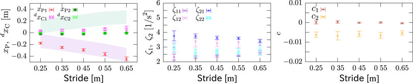
FIGURE 15. Identified parameters. Left: positions of pivot point and landing destination. Final position of COM is reset to be the original point. Magenta and green areas represent soles of pivot and landing feet, respectively. xP1 stays in pivot sole, and xP2, dxC1 and dxC2 are around 0. Middle: eigenvalues in each phase. The unstable eigenvalue ζ1* increased after landing, i.e., ζ11 < ζ12, while the stable eigenvalue ζ2* decreased, i.e., ζ21 > ζ22. Right: coefficient of inertial torque about COM. c1 ≃ 0 but c2 ≠ 0. All ζ*s and c*s are almost constant irrespective of step width, which supports the model.
More interestingly, it was verified that the parameters can be reasonably estimated only from partial observation of the motion data in time. Figure 16 shows xP1, xP2, dxC1 and dxC2 of experiments with different strides, where the abscissa means the percentage of the observation with respect to the whole data. The trajectory of the ZMP of the measured motion with a stride of 45 cm reproduced only from first 40% of the observed motion data in each phase is plotted in Figure 17, which fits the measured trajectory. Remember that xP ≠dxC and xP = dxC correspond to the stepping and braking motions, respectively. This implies that the intention, i.e., to step or to brake, of the measured subject can be guessed before completing even a half of the action.

FIGURE 16. xP1, xP2, dxC1 and dxC2 estimated from partial observations in time of experiments with different strides. The abscissa means the percentage of the observation with respect to the whole motion data.
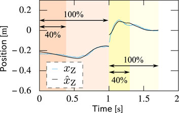
FIGURE 17. Comparison between measured and reproduced trajectories of the ZMP. The latter was reproduced only from first 40% of the observed motion data in each phase but fits the former.
Conclusion and Future Directions
A mathematical model of a step-and-brake control of a human subject was identified in a form of Eq. 16. The plausibility of the model at least with respect to the measured subject was shown as it reproduced trajectories of the COM and the ZMP in the overall motion process with a fair accuracy, which is a clear contribution of this work over the previous researches that focused on the capturability condition (Hof, 2008; Aftab et al., 2012). Note that we do neither mean to generalize the above discussion with only one subject nor immediately conclude that the identified model is best-suited for modeling of the behavior, but we think it could suggest the start point of discussions. Even though behaviors of only one subject were investigated in this work, highly resemblant output of the identified model to the measured data seems to us more than coincidental. It should be improved to be general through case studies and statistics of more subjects.
It was also shown that the control parameters could be estimated only from the first half movement before completing the action, with which the intention to step or to brake of the subject could be guessed. Thus, the authors think that the model is utilized in designing wearable assistive devices for human walking to recover balances and systems to evaluate humans’ balancing abilities on the fly. It is also an advantage of the proposed method for this purpose that it does not require a detailed body model of a human subject. We expect that the proposed controller model and protocol to identify it for individuals will benefit improvement of the quality of life of elderly and disabled people by detecting irregular behaviors of users only from their anticipatory movements and suggesting appropriate supportive actions of such devices.
On the other hand, there are still some technical issues to be considered for practical applications as well as how to measure the trajectory of the COM in real-time. It has to predict the remaining time to land and brake in advance in order to identify the parameters. Also, the effect of the inertial torque about the COM should be compensated in order to improve the accuracy. It is not trivial how to resolve the above problems and should be overcome in the future.
Data Availability Statement
The datasets presented in this article are not readily available because it includes personal information. Requests to access the datasets should be directed to zhidao@ieee.org.
Ethics Statement
Ethical review and approval was not required for the study on human participants in accordance with the local legislation and institutional requirements.
Author Contributions
• Conception and design of study: TS • Acquisition of data: MK, TS • Analysis and/or interpretation of data: MK, TS • Drafting the manuscript: TS, MK • Revising the manuscript critically for important intellectual content: TS • Approval of the version of the manuscript to be published: TS, MK.
Funding
The research was conducted with a financial support from Honda R&D Co.Ltd.
Conflict of Interest
Author TS is employed by OMRON Corporation.
The remaining author declares that the research was conducted in the absence of any commercial or financial relationships that could be construed as a potential conflict of interest.
Publisher’s Note
All claims expressed in this article are solely those of the authors and do not necessarily represent those of their affiliated organizations, or those of the publisher, the editors, and the reviewers. Any product that may be evaluated in this article, or claim that may be made by its manufacturer, is not guaranteed or endorsed by the publisher.
Acknowledgments
The authors cordially express our gratitude to Toru Takenaka and Taizo Yoshikawa for their contributions to this work through deep discussions.
References
Ae, M., Tang, H.-p., and Yokoi, T. (1992). Estimation of Inertia Properties of the Body Segments in Japanese Athletes. Biomechanisms 11, 23–33. doi:10.3951/biomechanisms.11.23
Aftab, Z., Robert, T., and Wieber, P.-B. (2012). Predicting Multiple Step Placements for Human Balance Recovery Tasks. J. Biomech. 45, 2804–2809. doi:10.1016/j.jbiomech.2012.08.038
Alexander, R. M. (1976). Mechanics of Bipedal Locomotion, 1. Oxford: Pergamon, 493–504. doi:10.1016/b978-0-08-018767-9.50047-0
Cavagna, G. A., and Margaria, R. (1966). Mechanics of Walking. J. Appl. Physiol. 21, 271–278. doi:10.1152/jappl.1966.21.1.271
Harada, K., Kajita, S., Kaneko, K., and Hirukawa, H. (2006). An Analytical Method for Real-Time Gait Planning for Humanoid Robots. Int. J. Hum. Robot. 03, 1–19. doi:10.1142/s0219843606000643
Hase, K., and Yamazaki, N. (1998). Computer Simulation of the Ontogeny of Bipedal Walking. As 106, 327–347. doi:10.1537/ase.106.327
Herdt, A., Diedam, H., Wieber, P.-B., Dimitrov, D., Mombaur, K., and Diehl, M. (2010). Online Walking Motion Generation with Automatic Footstep Placement. Adv. Robotics 24, 719–737. doi:10.1163/016918610x493552
Hof, A. L. (2008). The 'extrapolated center of Mass' Concept Suggests a Simple Control of Balance in Walking. Hum. Move. Sci. 27, 112–125. doi:10.1016/j.humov.2007.08.003
Kajita, S., Kanehiro, F., Kaneko, K., Fujiwara, K., Harada, K., Yokoi, K., et al. (2003). “Biped Walking Pattern Generation by Using Preview Control of Zero-Moment Point,” in Proceedings of the 2003 IEEE International Conference on Robotics & Automation, Taipei, Taiwan, September 14–19, 2003, 1620–1626.
Kojima, M., and Sugihara, T. (2020). “Identification of a Step-And-Brake Controller of a Human Based on COM-ZMP Model and Terminal Capturability Condition,” in The 8th IEEE RAS/EMBS International Conference on Biomedical Robotics and Biomechatronics, New York, NY, November 29–December 1, 2020, 165–170. doi:10.1109/biorob49111.2020.9224372
Koolen, T., de Boer, T., Rebula, J., Goswami, A., and Pratt, J. (2012). Capturability-based Analysis and Control of Legged Locomotion, Part 1: Theory and Application to Three Simple Gait Models. Int. J. Robotics Res. 31, 1094–1113. doi:10.1177/0278364912452673
Lee, C. R., and Farley, C. T. (1998). Determinants of the center of Mass Trajectory in Human Walking and Running. J. Exp. Biol. 201, 2935–2944. doi:10.1242/jeb.201.21.2935
McMahon, T. A. (1984). Mechanics of Locomotion. Int. J. Robotics Res. 3, 4–28. doi:10.1177/027836498400300202
Mitobe, K., Capi, G., and Nasu, Y. (2000). Control of Walking Robots Based on Manipulation of the Zero Moment point. Robotica 18, 651–657. doi:10.1017/s0263574700002708
Morimoto, J., Endo, G., Nakanishi, J., and Cheng, G. (2008). A Biologically Inspired Biped Locomotion Strategy for Humanoid Robots: Modulation of Sinusoidal Patterns by a Coupled Oscillator Model. IEEE Trans. Robot. 24, 185–191. doi:10.1109/tro.2008.915457
Nagasaka, K., Kuroki, Y., Suzuki, S., Itoh, Y., and Yamaguchi, J. (2004). “Integrated Motion Control for Walking, Jumping and Running on a Small Bipedal Entertainment Robot,” in Proceedings of the 2004 IEEE International Conference on Robotics and Automation, New Orleans, LA, April 26–May 1, 2004, 3189–3914. doi:10.1109/robot.2004.1308745
Pratt, J., Carff, J., Drakunov, S., and Goswami, A. (2006). “Capture Point: A Step toward Humanoid Push Recovery,” in Proceeding of the 2006 IEEE-RAS International Conference on Humanoid Robots, Genova, Italy, December 4–6, 2006, 200–207. doi:10.1109/ichr.2006.321385
Ren, L., Howard, D., and Kenney, L. (2006). Computational Models to Synthesize Human Walking. J. Bionic Eng. 3, 127–138. doi:10.1016/s1672-6529(06)60016-4
Schmitthenner, D., and Martin, A. E. (2021). Comparing System Identification Techniques for Identifying Human-like Walking Controllers. R. Soc. Open Sci. 8, 211031. doi:10.1098/rsos.211031
Shachykov, A., Shuliak, O., and Henaff, P. (2019). “Closed-loop Central Pattern Generator Control of Human Gaits in OpenSim Simulator,” in 2019 International Joint Conference on Neural Networks, Budapest, Hungary, July 14–19, 2019. doi:10.1109/ijcnn.2019.8852163
Sugihara, T., Kaneta, D., and Murai, N. (2022). Identification of COM Controller of a Human in Stance Based on Motion Measurement and Phase-Space Analysis. Front. Robot. AI 8, 729575. doi:10.3389/frobt.2021.729575
Sugihara, T., and Morisawa, M. (2020). A Survey: Dynamics of Humanoid Robots. Adv. Robotics 34, 1353–1369. doi:10.1080/01691864.2020.1778524
Sugihara, T., and Nakamura, Y. (2009). Boundary Condition Relaxation Method for Stepwise Pedipulation Planning of Biped Robots. IEEE Trans. Robot. 25, 658–669. doi:10.1109/tro.2008.2012336
Sugihara, T., Nakamura, Y., and Inoue, H. (2002). “Realtime Humanoid Motion Generation through ZMP Manipulation Based on Inverted Pendulum Control,” in Proceedings of the 2002 IEEE International Conference on Robotics & AutomationWashington D.C., May 11–15, 2002, 1404–1409.
Sugihara, T. (2009). “Standing Stabilizability and Stepping Maneuver in Planar Bipedalism Based on the Best COM-ZMP Regulator,” in Proceedings of the 2009 IEEE International Conference on Robotics & Automation, Kobe, Japan, May 12–17, 2009, 1966–1971. doi:10.1109/robot.2009.5152284
Sugihara, T., and Yamamoto, T. (2017). “Foot-guided Control of a Biped Robot that Guarantees Standing Stability at Landing,” in Proceedings of 2017 IEEE/RSJ International Conference on Intelligent Robots and Systems, Vancouver, BC, September 24–28, 2017, 4546–4551.
Taga, G. (1995). A Model of the Neuro-Musculo-Skeletal System for Human Locomotion. Biol. Cybern. 73, 97–111. doi:10.1007/bf00204048
Vukobratović, M., and Stepanenko, J. (1972). On the Stability of Anthropomorphic Systems. Math. Biosciences 15, 1–37.
Whittle, M. W. (1997). Three-dimensional Motion of the center of Gravity of the Body during Walking. Hum. Move. Sci. 16, 347–355. doi:10.1016/s0167-9457(96)00052-8
Xiang, Y., Arora, J. S., and Abdel-Malek, K. (2011). Optimization-based Prediction of Asymmetric Human Gait. J. Biomech. 44, 683–693. doi:10.1016/j.jbiomech.2010.10.045
Yamamoto, T., and Sugihara, T. (2020). Foot-guided Control of a Biped Robot through ZMP Manipulation. Adv. Robotics 34, 1472–1489. doi:10.1080/01691864.2020.1827031
Yamashita, T., Yamada, M., and Inotani, H. (1972). A Fundamental Study of Walking (In Japanese). Biomechanics 1, 226–234.
Keywords: biped locomotion, step-and-brake motion, human motor control, COM-ZMP model, system identification, capturability
Citation: Kojima M and Sugihara T (2022) Identification of a Step-And-Brake Controller of a Human Based on Prediction of Capturability. Front. Robot. AI 9:729593. doi: 10.3389/frobt.2022.729593
Received: 23 June 2021; Accepted: 07 March 2022;
Published: 28 April 2022.
Edited by:
Tadej Petric, Institut Jožef Stefan (IJS), SloveniaReviewed by:
Robert Griffin, Florida Institute for Human and Machine Cognition, United StatesHassãne Gritli, University of Tunis, Tunisia
João Paulo Morais Ferreira, Superior Institute of Engineering of Coimbra (ISEC), Portugal
Copyright © 2022 Kojima and Sugihara. This is an open-access article distributed under the terms of the Creative Commons Attribution License (CC BY). The use, distribution or reproduction in other forums is permitted, provided the original author(s) and the copyright owner(s) are credited and that the original publication in this journal is cited, in accordance with accepted academic practice. No use, distribution or reproduction is permitted which does not comply with these terms.
*Correspondence: Tomomichi Sugihara, emhpZGFvQGllZWUub3Jn