 Yoeko Xavier Mak
 Hamid Naghibi
 Momen Abayazid
- Robotics and Mechatronics Group, Faculty of Electrical Engineering, Mathematics and Computer Science, Technical Medical (TechMed) Centre, University of Twente, Enschede, Netherlands
Fiber reinforced soft pneumatic actuators are hard to control due to their non-linear behavior and non-uniformity introduced by the fabrication process. Model-based controllers generally have difficulty compensating non-uniform and non-linear material behaviors, whereas model-free approaches are harder to interpret and tune intuitively. In this study, we present the design, fabrication, characterization, and control of a fiber reinforced soft pneumatic module with an outer diameter size of 12 mm. Specifically, we utilized the characterization data to adaptively control the soft pneumatic actuator. From the measured characterization data, we fitted mapping functions between the actuator input pressures and the actuator space angles. These maps were used to construct the feedforward control signal and tune the feedback controller adaptively depending on the actuator bending configuration. The performance of the proposed control approach is experimentally validated by comparing the measured 2D tip orientation against the reference trajectory. The adaptive controller was able to successfully follow the prescribed trajectory with a mean absolute error of 0.68° for the magnitude of the bending angle and 3.5° for the bending phase around the axial direction. The data-driven control method introduced in this paper may offer a solution to intuitively tune and control soft pneumatic actuators, compensating for their non-uniform and non-linear behavior.
1 Introduction
The compliant nature of soft pneumatic actuator has led to its widespread development for minimally invasive surgery (MIS) applications, as shown in the review paper by Runciman et al. (2019). However, these soft mechanisms have lower overall precision and repeatability compared to rigid link actuators (Burgner-Kahrs et al., 2015; Katzschmann et al., 2015). Moreover, fiber reinforcement is often added to soft actuators for controlling the mode of deformation and improve the power transfer. On the other hand, fiber reinforcement increases the non-linear response, the complexity of modeling, and control of such actuators (Fras and Althoefer, 2019; Sun et al., 2021).
Previous studies on fiber reinforced soft pneumatic actuator (SPA) design use reinforcements inside the pneumatic module, such as works by Li et al. (2020) and Dawood et al. (2021), or on the exterior of the soft module, such as works by Wirekoh et al. (2020) and Singh et al. (2018). Although internal reinforcement designs are modular and the internal deformation is more uniform, external reinforcement designs are more space efficient, which is needed for MIS.
There are two main control methods for soft actuators based on the usage of the model by the controller: model-based and data-driven controllers (George Thuruthel et al., 2018).
Modeling of soft mechanisms is more difficult and computationally intensive, compared to rigid body systems, because of its complex shape deformation. Various real time modeling and control approaches for a soft pneumatic actuator based on analytical modeling have been demonstrated, such as using Cosserat rod mechanics (Renda et al., 2018; Chikhaoui et al., 2019; Till et al., 2019), beam theory (Ataka et al., 2020), and Langrangian formulation (Sadati et al., 2018). An alternative approach to analytical modeling for control is to use the output of a finite element (FE) model in the controller framework (Faure et al., 2012; Duriez, 2013). FE model can also be used to control a soft robot adaptively through the use of gain-scheduling controllers (Wu and Zheng, 2021).
Data-driven or black-box controllers do not require explicit input of parameters of the physical system during development and tuning. For this reason, these approaches perform better for systems that are highly influenced by non-linearities and hard-to-model ‘real-world effects’ such as friction (Vikas et al., 2016), hysteresis caused by the soft material or actuation behaviour (Truby et al., 2020), and non-uniformity of the soft robot design (Giorelli et al., 2015). An example of a data-driven control method has been presented by Bruder et al. (2021), using a Koopman system identification in combination with a model predictive control (MPC) framework. An approach using supervised learning to develop a black-box model for control, tested on a cable-driven soft robot, has been introduced by Bern et al. (2020). An alternative data-driven control can be achieved using reinforcement learning (RL). Ansari et al. (2018) introduced a hybrid tendon and pneumatically actuated soft module that was controlled by an RL agent, optimizing its end-effector position and module stiffness. Despite the advantage in accuracy for these cases, data-driven controllers generally are harder to tune intuitively compared to model-based approaches, since the system behavior is driven by the learned/identified input-output mappings.
In this study, we present the design, characterization, and control of a fiber reinforced soft pneumatic actuator for the application of endoscopic surgery. We developed a data-driven control framework to compensate the ‘real-world effects’ such as non-linear mechanics and non-uniformity of the physical module while maintaining the ability to tune the controller behavior intuitively through the adaptive controller framework. Specifically, our contributions are: 1) introduction of a 12 mm diameter fiber reinforced SPA for endoscopy application, 2) mechanical characterization of the soft pneumatic actuator for its bending and force performance, 3) control of a soft pneumatic actuator using an adaptive controller based on the experimentally obtained characterization curve.
2 Soft pneumatic actuator module
In this section, we present the design, finite element modeling, and fabrication method of the fiber reinforced SPA employed in this study.
2.1 Design rationale
The design of the actuator module is based on the use case for endoscopic intervention, where the developed module will be fitted to the tip of the endoscope. This work focuses on the development of a single-module soft actuator and its control method. In particular, tool designs such as the addition of endoscopic working channels, a camera, and illumination are not included in our current study.
For endoscopic surgery, the soft actuator is required to have 2 degrees of freedom (DOF) bending motion in order to have the same capability as currently used endoscopes for gastro-intestinal or colon interventions. This already brings an improvement to the currently used endoscopes, by ensuring compliance at the material level, the soft actuator reduces the risk of tissue damage and punctures. The design choices and requirements of the SPA are presented in Table 1.
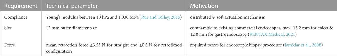
TABLE 1. Design choices and requirements of the fiber reinforced soft pneumatic endoscope module.
To achieve the required 2 DOF bending motion, we designed the actuator to have 3 pneumatic actuation chambers within the module. Although 2 DOF bending can theoretically be performed only using 2 separate actuation chambers, we opted to have a symmetrical arrangement using 3 chambers. Actuation using only two chambers would require the module to be prebent, or actuated using negative pressure (vacuuming), which makes the actuator response asymmetric between left-right (and up-down).
We designed the geometry of the SPA, such that the cross-sectional area of the pneumatic actuation chambers is maximized, while allowing extra space in the center for further development of the endoscope (e.g., cables for the camera, endoscope working channels, etc.). This will improve the actuation force as the force is the cross-section area size times the chamber pressure difference to the ambient pressure. This resulted in an arc-shaped chamber design as seen in Figure 1A. Fiber reinforcement is added to the exterior of the soft module to limit excessive radial deformation.

FIGURE 1. The developed FE model of the soft pneumatic actuator with the outer fiber reinforcement constraint (A). The bending performance is simulated for the case of single chamber pressurization (B), and pressurization of two chambers at once (C).
2.2 Finite element modeling
To speed up the design process of the SPA, a finite element (FE) model was developed using Abaqus v2018 (Simulia, United States). The developed FE model helps to estimate the mechanical behavior of the proposed actuator without going through the lengthy fabrication process repeatedly. The CAD model of the module was imported and meshed with 10-node modified quadratic tetrahedron (C3D10M) elements. A Neo-Hookean hyper-elastic isotropic model was used to model the mechanical behavior of the inner module, in which the strain energy function ψ is described as a function of the first invariant of the left Cauchy-Green deformation tensor I1 and the elastic volume ratio J:
where C10 and D are the Neo-Hookean constants and the inverse of the bulk modulus, respectively. Holzapfel-Gesser-Ogden hyperelastic material model was utilized to model the behavior of the outer fiber reinforcement. The strain energy function is described as a function of Neo-Hookean terms, representing the non-collagenous matrix, and I4(αα), pseudo-invariants of
with:
The constants k1 and k2 are material parameters and κ describes the level of dispersion in the fiber directions. Based on our previous study (Lenssen et al., 2019), the material coefficients for the module and the fiber reinforcement were adjusted from the material data sheet and bending experiments (C10 = 0.1 MPa, D = 0.01 MPa−1, k1 = 70 MPa, k2 = 0.3, κ = 0.1). Pressure was applied with a linear profile over time and (quasi-static) implicit analysis was completed using a standard Abaqus solver.
2.3 Soft pneumatic module fabrication
The inner module of the soft pneumatic actuator was made of silicone material (EcoFlex 0050, Smooth-On Inc.). Before the casting process, the silicone resin was vacuumed to remove air bubbles from the material. Subsequently, the resin was poured into a custom-made modular mold in a three-step casting process, as shown in Figure 2. We used a braided polyester cable sleeve as the external fiber reinforcement of the actuator. The cable sleeve is compressed to the same length as the inner silicone module (Supplementary Material S1), and then each end of the cable sleeve is glued to the inner module.
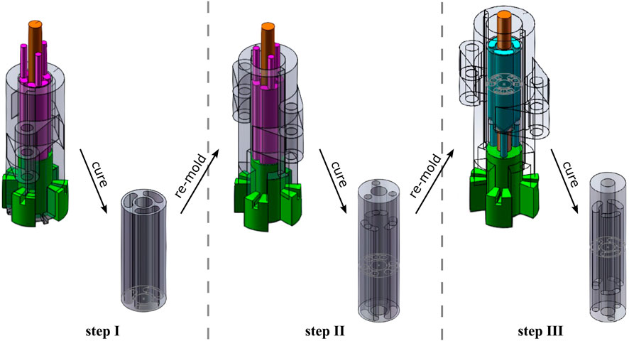
FIGURE 2. The module casting process is divided into three steps: the section with air chambers is molded in step I, while the foot and cap section is fabricated in step II and III respectively. For all steps, the silicone resin is poured from the top side of the mold.
2.4 Setup
Figure 3 shows the setup used to characterize and control the fabricated soft pneumatic module. The air pressures of the chambers were modulated using three pressure regulators (VEAB-L-26-D2-Q4-V1-1R1, Festo AG & Co. KG, Germany). The regulators were connected to an Arduino Uno (Arduino, United States), augmented with a driver board to power and send control signals to the regulators. To measure the orientation of the soft module end effector, a miniature 6 DOF electromagnetic (EM) NDI Aurora sensor (Northern Digital, Canada) was placed at the tip of the module. Additionally, a calibrated load cell was fixed in place and was used to measure the bending force in the radial direction, as shown in Figure 3C.
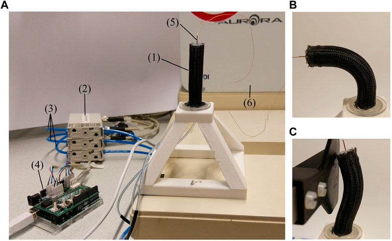
FIGURE 3. The experimental setup (A) for characterization and control of the soft pneumatic endoscope, consisting of: (1) the soft pneumatic module, (2) three pneumatic regulators connected to (3) pressurized air input (2 bar), (4) an Arduino with driver board, and (5) an electromagnetic pose sensor with (6) the EM-field generator. Figures (B) and (C) show the soft pneumatic module during motion and force characterization, respectively.
3 Modeling
The module can be controlled in 3 DOF using 3 actuation chambers, e.g., θ, ϕ, ℓ which respectively are the end-effector bearing angle in the lateral direction, the phase angle of the bending plane around the vertical axis, and the length of the module. However, the elongation movement has practically limited use for endoscopic applications, as the insertion movement of the overall endoscope tool covers a larger change of length compared to the extension limit of the actuator. Therefore, we opted to control only the bending angles, actuating a maximum of 2 chambers simultaneously, to maximize the bending angle θ, which occurs when ℓ is minimum.
3.1 Robot kinematics
Piecewise constant curvature (PCC) kinematic assumption is used, enabling rigid-body techniques to be used for flexible mechanisms (Webster and Jones, 2010). The forward kinematics of the proposed SPA is constructed using this PCC assumption, as presented for the case of generic continuum robots by Webster and Jones (2010). However in our case, we used the bearing angles in each of the chamber’s bending plane as the actuator space variables qi, instead using the chamber’s lengths.
The transformation from the base of the module to end-effector is given by:
where
where pCC is the translation vector between the start to the end of the constant curvature section, given by
Following Eq. 5, the general constant curvature forward kinematics is written as:
where
This forward kinematics is extended to the actuator space (qi where i = 1, 2, 3), which is the end-effector orientation projected on the plane of bending of each respective chamber. These actuator space variables describe the bending contribution of each chamber towards the overall orientation of the actuator module. While θ and ϕ describe the orientation of the end-effector, where θ is the angle of deviation from the straight orientation, and ϕ is the phase angle around the vertical axis, as shown in Figure 4.
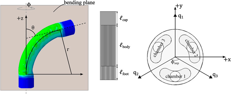
FIGURE 4. Kinematic representation of the PCC segment for the soft pneumatic endoscope module.
The configuration space variables θ and ϕ are expressed in qi as:
where ϕsep is the separation angle between each bending plane. The value of ϕsep = 132° is obtained experimentally during the characterization process. This value is higher than 120° due to the expansion of the chambers during actuation, as shown in Figure 1C.
3.2 Motion characterization
The general dynamics model of a generic soft robot (Della Santina et al., 2020) can be written as:
where M(q) is the robot’s inertia matrix,
The identification of K(q) was performed using characterization experiments, in which the module is actuated slowly to not excite the dynamic terms. When only a single chamber is actuated at a time, the bending angle at the end-effector, qi ∈ q is mapped to the chamber’s input pressure ui through:
Combining Eqs 8 and 10, the static map from input pressures to the orientation of the end effector is obtained.
4 Experimental characterization
Based on the model described in the previous section, we characterized the relationship between the angle of bending θ and the pressure of the chamber ui. Furthermore, a force characterization experiment was conducted to evaluate the amount of lateral force the designed SPA can exert.
4.1 Steady-state motion characterization
In the motion characterization experiment, the chambers were actuated one at a time. In this case, the end-effector bending angle θ is equal to the angle of the actuation chamber qi, following Eq. 8. Therefore, the mapping between end-effector angle θ and input pressure ui during this characterization process is described in Eq. 10.
Characterization was performed using ascending and descending pressure sweeps to account for hysteresis behavior (4 cycles for each chamber). The tip orientation had to reach steady state before the next input pressure value was sent to the regulator, to prevent dynamic effects. The step change in the pressure values was set to the resolution of the pressure regulator (Δui = 0.00195 bar). All actuator chambers are preloaded with 0.05 bar nominal pressure to avoid the discontinuous behavior of the pressure regulator during the initialization phase and to fill the remaining gap between the inner silicone module and the outer fiber, so that the module can immediately bend when pressure is applied.
Similar procedures were performed for two-chamber actuation at the same time, ui = uj and (i, j) = (1, 2) (2, 3), (1, 3). These two-chamber actuation experiments are performed to validate if the single-chamber characterization curve can be used to estimate bending in other directions. The maps obtained from the two-chamber actuation experiments are not used for the control of the actuator. The actuator angles qi with i = 1, 2, 3, obtained in the single-chamber characterization, are substituted in Eq. 8 to calculate the estimated bending angle
We expected hysteresis in the measurement of the characterization curve, which is caused by the intrinsic behavior of the elastomer and the friction between the outer reinforcement fiber and the inner silicone module. To quantify hysteresis in the characterization curve, the percentage difference between the measured bending angle during the ascending phase (qasc) and the descending phase (qdesc) is given as
The hysteresis percentage hq was calculated for all single chamber characterization curves.
The results of the characterization experiments are presented in Figure 5. The input pressure and the bending angle are presented on the vertical and horizontal axes, respectively, to mimic the hyperelastic stress-strain curve at the material level. Furthermore, the result of the characterization experiment is compared with the FE simulation results. The characterization curve follows a shape similar to that of the FE simulation output. The variation between results for the three bending planes (for each chamber) can be attributed to non-uniformity of the prototype due to the manual casting process. Furthermore, uneven compression of the outer reinforcement fiber layer during the fabrication process might affect the maximum bending for the different bending planes. Although the module behaves non-uniformly, the motion is repeatable. Figure 5 shows that the resulting curve from the four ascending and descending cycles coincides for all three cases.
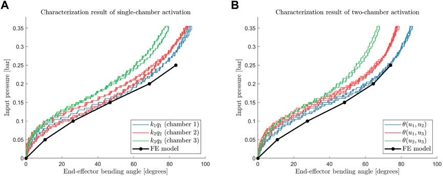
FIGURE 5. Angle to input pressure relation at steady-state when only single actuation chamber is pressurized (A), and two actuation chambers are pressurized simultaneously (B) along with each finite element model outputs.
The means of hysteresis hq are 3.82%, 6.70%, and 2.63%, for the characterization of chamber 1, chamber 2, and chamber 3, respectively. These values are comparable to the amount of hysteresis found in the EcoFlex 00-50 tensile test (Liao et al., 2020), which is used as the soft material of the inner module.
Furthermore, we compare the results of two-chamber activation experiments with an estimate constructed using the single-chamber characterization data. The experimentally measured curves of two-chamber activations are compared with the calculated estimate
The characterization curve can be fitted and utilized to construct a control input signal that compensates for the stiffness term in the model.
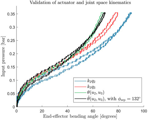
FIGURE 6. Comparison between estimated curve using the generalized 2D kinematics (shown in black) to the experimentally measured bending data (green) shows agreement for the simultaneous activation of chamber 2 and 3.
4.2 Force characterization
In addition to the previous setup, a strain gauge load sensor connected to a rigid force plate was used to measure this interaction force (Figure 3). The load sensor was calibrated using a set of calibrated masses prior to the force characterization experiment. In this case, the force was measured only in the lateral direction since the axial movement is not controlled. Consequently, in our current implementation, the axial force depends only on the inherent stiffness of the actuator.
The results of the force characterization are presented in Figure 7. The result of the force measurements shows that the module can exert a maximum lateral force of 0.33 ± 0.03 N for a single chamber and 0.34 ± 0.03 N for two-chamber activation, at 0.4 bar pressure in the reference kinematic configuration (straight). Although these force values are lower than the force required in practice, the lateral direction is the weakest direction to which the endoscope can apply force. The force values in the design requirement (Section 2.1) represent the maximum forces throughout the entire endoscopic biopsy procedure and are not restricted to a single axis. This means that these values can occur during the retraction movement during the biopsy procedure. Increasing the force that the endoscope can apply is part of our future work and is still an open problem for small-scale soft actuators.
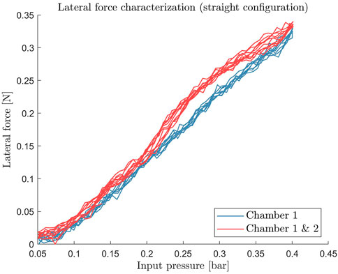
FIGURE 7. Static lateral force measurement of the soft pneumatic actuator module. The force is measured over the range of operating input pressure of 0 bar–0.4 bar.
5 Control strategy
5.1 Fitting of the characterization curve
Characterization data was used to construct the forward and backward map between the input pressures ui and the actuator angles qi. Sixth-order polynomial curves were fitted to each of the single-chamber characterization curves, as shown in Figure 8. The backward mapping from qi to the input pressure ui is given by:
where ai,6, ai,5, … , ai,0 are the sixth-order polynomial fitting coefficients presented in Table 2. The fitted curves were used to construct feedforward signals and adaptive feedback parameters (explained in Section 5.3).
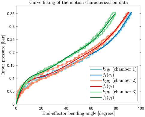
FIGURE 8. Sixth order polynomial fit of all single chamber activation motion characterization curves.
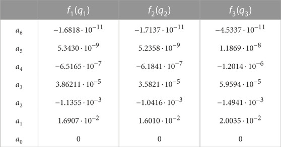
TABLE 2. Polynomial fitting coefficients for the map from qi to ui for single-chamber characterization curves.
Table 3 shows the fitting errors to the experimentally obtained characterization data. Since the hysteresis behavior was not taken into account in the fitting, this error will be compensated for by the feedback controller.
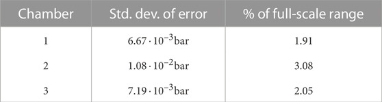
TABLE 3. Standard deviation of the difference between the fitted curves and the measured characterization data.
5.2 Module’s workspace
Using the fitted curve and the kinematic mapping (Section 3.1), we can construct the module’s end-effector positions in 3D coordinate based on the kinematic model.
Figure 9 visualizes the robot workspace based on the operating input pressure level. We observe regions that require low and high input pressures to reach steady-state configuration. The maximum bending angles for the single-chamber actuation for chambers 1, 2, and 3, respectively, are 92.3°, 90.4°, and 79.5° at 0.4 bar (including 0.05 bar preloading pressure). The three other vertices in the hexagonal workspace shape (Figure 9, right image) represent the maximum bending when two chambers are pressurized simultaneously, which are 86.2°, 78.9°, and 67.9° at 0.4 bar.
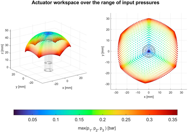
FIGURE 9. Robot’s 2D workspace in 3D space, based on the characterization data combined with module kinematics. High input pressure regions are shown in red, while low input pressure regions are shown in blue.
5.3 Adaptive controller framework
The controller consists of a feedforward signal and an adaptive feedback controller. Fitted motion characterization data were used in both feedforward and feedback control. For the feedforward signal, the fitted curves were used in combination with the kinematics model (Eq. 5 and 8 to compensate for the static behavior of the module. In the case of the adaptive feedback controller, the fitted curves were used to construct the adaptive parameter used to scale the feedback gains.
We further separated the stiffness term in the system model, where it can be compensated by the feedforward term of the controller. From Eq. 9, the complete controlled system can be formulated as
where uff and ufb are the feedforward and feedback control efforts, and
contains the residual dynamics and gravity effect terms that are not known from the characterization and design parameters.
5.3.1 Feedforward signal using motion characterization fitting
Similar to the steps presented in Section 5.2, a map is constructed from the configuration parameters (θ and ϕ) to the required feedforward signal for each actuator uff,i. Inverse kinematics was used to calculate the required actuator angles qi from the reference θ and ϕ. Subsequently, the feedforward control effort is calculated using the polynomial fit uff = f(q), where
The feedforward functions estimate the stiffness term K(q)q, which left the remaining dynamics as
5.3.2 Adaptive feedback control
While feedback control can be implemented using a PID controller based on the measured orientation of the end effector, the module behavior is highly non-linear, meaning that the required controller gain might change depending on qi. We employ an adaptive gain-scheduling control strategy to interpolate and scale the controller gains based on the obtained characterization data. Adaptive gain scheduling as a control technique is a standard approach in the field of control theory (Bett, 2005; Anh, 2010; Åström and Wittenmark, 2013; Wu and Zheng, 2021). In this study, we introduce a technique where the characterization data of the soft actuator is used to build the gain scheduling parameter. Hence, adaptive control can be performed on the entire workspace without sampling the whole workspace itself (such as in the case when using reinforcement learning type of algorithms).
Although not all soft pneumatic actuator dynamics is known (for example, centrifugal and damping terms), the stiffness term ki (qi) can be utilized as an adaptive scaling parameter. However, this requires the assumption that the reference trajectory dynamics is slowly varying, and therefore, the stiffness term would dominate around this low-frequency region.
This adaptive scaling parameter can be constructed by estimating ki (qi). From Eq. 10, the estimate
In general, the feedback controller can be implemented in the actuator space (control effort based on qi) or in the configuration space (based on θ and ϕ). We opted to implement the controller in the actuator space so that the controller PID gains are set independently for each chamber. This enables a more precise tuning to counteract the non-uniformity of the module (Penning et al., 2012).
The state space form based on Eq. 16 was constructed and subsequently linearized at some chosen operating points (Bett, 2005). A PID controller was implemented and tuned at these selected points.
and
We define the equilibrium points
Thus, the feedback control effort can be formulated as
where e is the actuator space error, defined by
and upid contains the classical PID terms:
where Kp, Ki, and Kd are diagonal matrices containing the PID gains.
We selected two equilibrium points for each actuation chamber, one in a configuration where
where
Similarly, this adaptive gain tuning method was also performed for the I and D gains. We tuned the PID gains at the two equilibrium configurations
5.4 Experimental validation
A trajectory tracking experiment was conducted to validate the performance of the control method. Using the same setup as the experimental characterization experiment (Section 2.4, the bending angles were measured at the tip of the endoscope using an electromagnetic tracker. Subsequently, the feedback and feedforward control efforts are calculated using the methods described above.
A square reference trajectory was used to validate the tracking accuracy of the soft pneumatic system. The maximum bending angles are 35° (at the corners of the square trajectory), and the endoscope tip traced the entire square with a period of 30 s. The tracking experiment is performed over 2 laps of the square trajectory.
6 Results and discussions
6.1 Tracking accuracy results
The result of the tracking experiment following the trajectory is shown in Figure 10. Keep in mind that the controller controls the tip angles, not the position in Cartesian coordinates, as motivated in Section 3. The measured tip positions shown in Figures 10A, B, are calculated using the kinematic model described in Section 3.1.
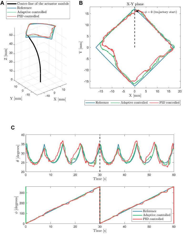
FIGURE 10. The visualization of the actuator tracking a square reference trajectory in 3D is presented in (A), while the tip position from the top-down view is shown in (B). The tracking results of the tip orientation angles (θ and ϕ) are shown in (C). The black dashed lines indicate the start of the second lap of the square trajectory.
Over 2 laps of the square reference trajectory, the actuator was able to track the trajectory with a mean absolute error of 0.75° for the bending angle θ and 1.8° for the phase angle ϕ. The mean absolute error for the bending angle θ is 2.1% of the reference trajectory’s bending range and 0.5% for the phase angle ϕ. Using the proposed adaptive controller framework, the endoscope was able to track the reference trajectory angles with reasonable accuracy.
6.2 Discussions
The results of the adaptive controller indicate closer tracking of the reference trajectory compared to conventional PID control, as shown in Figures 10A–C. The adaptive parameter based on the stiffness of the characterized module enables the adaptive PID controller to be tuned with a higher gain at bent configuration (Figure 11). In contrast, the conventional PID controller can only be tuned at lower constant Kp gain, before it exhibits unstable oscillations. The adaptive controller is able to set its gain to a higher value in the bent configuration and lower in the straight configuration, while the conventional PID controller is fixed at constant gain values.
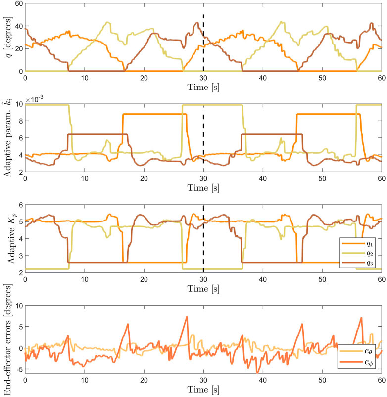
FIGURE 11. From top to bottom: the actuator space bending angles q, the adaptive parameter
The error at the left corner in Figure 10B are present for both the adaptive and conventional PID controlled actuator. At this location, the tip orientation is highly dependent on the contribution of chamber 2. Initially, we think that this error is caused by the uncompensated hysteresis behavior (which is the largest in chamber 2). However, if we compare Figures 10B, C, this error is more apparent in the position plot (Figure 10B) than the orientation plot (Figure 10C, visible at t ≈ 20 sec and t ≈ 50 sec). This indicates that the actuator is able to point to the reference direction, however, the resulting tip position is not correct. Therefore, it means that PCC kinematic assumption does not perform well specifically for this configuration. This may have been caused by the uneven thickness of the inner silicone wall due to manual fabrication, which caused the actuator to bend in a different amount of curvature over the length of the actuator. The PCC assumption is a major source of error for the end-effector position estimate. Moreover, using PCC introduces a kinematic singularity in the straight configuration. Alternative solutions, such as variable curvature kinematics in Huang et al. (2021), might solve the aforementioned problems.
Our approach in using data-driven adaptive control based on characterization is a way to compensate for real-world effects that are difficult to model, such as material non-linearity and non-uniformity due to design and fabrication steps. Although the non-linearity in this case includes the change in sensitivity over different bending configurations, the compensation for hysteresis and other path-dependent behaviors has not been compensated yet. The hysteresis behavior might cause limit-cycle behavior in the resulting controlled behavior. This is shown as the low magnitude but high-frequency motion in the tracking results in Figure 10.
The dynamics of the pressure regulator significantly affects the tracking results. The resolution of the pressure regulators was limited to 8 bits over 2 bar full-scale range. This limitation can be noticed in Figures 10B, C where the measured tip orientation showed a staircase-like behavior, where the step size of the staircase indicates the resolution of the pneumatic regulator hardware. This behavior sets the lower bound of the tracking error in our implementation.
The initial setting of the outer reinforcement fiber during the fabrication of the SPA strongly influences the maximum bending angle of the module (as presented in the Supplementary Material S1). Compressing the reinforcement fiber during fabrication will increase the maximum bending response limit of the soft actuator. However, this increases the risk of non-uniform bending response magnitude between individual actuation chambers due to uneven compression due to the manual fabrication process. Consequently, this phenomenon also leads to non-uniform separation angles ϕsep between the actuation chambers, namely, ϕsep between chambers 1 and 2, 2 and 3, 1 and 3.
Since the scope of this study does not include the overall endoscope design, the response of the endoscopic actuator when a camera or tools are included might add non-linearity components to the actuator response. We expect that the complex interaction from the added tool/tube will increase the amount of non-linearity in the function map. More tuning points could be used to tune the adaptive controller to compensate for the complex actuator behavior.
We realize that further investigation is needed related to the response of the controller against external perturbations. In this work, we focused on the accuracy and repeatability of the soft pneumatic actuator, especially with regard to how the controller can compensate for the complex and non-uniform behavior of the actuator. The response of the soft pneumatic endoscope to external perturbations will be addressed in our future work. Furthermore, the actuator response should be investigated for different external impulse directions in different configurations.
7 Conclusion
We presented the FE simulation, characterization, and control of a fiber reinforced soft pneumatic actuator. The module was characterized to determine the mapping between the required pressures in the actuation chambers and the orientation angles of the tip. These experimentally obtained characterization data were used to construct an adaptive controller to follow a prescribed tip orientation trajectory in 2D. Using the data-driven adaptive control framework, the non-linear material behavior and non-uniformity of the fiber reinforced SPA can be compensated while maintaining the ability to intuitively tune and adjust the behavior of the controller. The results of the tracking experiment show that the proposed control method can follow a prescribed reference trajectory in real time. Our future work will focus on improving the accuracy of the kinematic model and including a hysteresis model in actuator space mapping, to further improve the control of a fiber reinforced soft pneumatic actuator.
Data availability statement
The raw data supporting the conclusion of this article will be made available by the authors, without undue reservation.
Author contributions
YM and MA conceptualized the study. YM performed the characterization experiments, implemented the control algorithm, and wrote the original draft. HN performed the finite element simulation and contributed to the writing of the manuscript. YL designed and fabricated the prototype. MA supervised the work, reviewed, and edited the manuscript.
Funding
This work is financially supported in part by ITEA under the 17021 IMPACT and 20044 ASSIST project.
Conflict of interest
The authors declare that the research was conducted in the absence of any commercial or financial relationships that could be construed as a potential conflict of interest.
Publisher’s note
All claims expressed in this article are solely those of the authors and do not necessarily represent those of their affiliated organizations, or those of the publisher, the editors and the reviewers. Any product that may be evaluated in this article, or claim that may be made by its manufacturer, is not guaranteed or endorsed by the publisher.
Supplementary material
The Supplementary Material for this article can be found online at: https://www.frontiersin.org/articles/10.3389/frobt.2023.1056118/full#supplementary-material
References
Anh, H. P. H. (2010). Online tuning gain scheduling MIMO neural PID control of the 2-axes pneumatic artificial muscle (PAM) robot arm. Expert Syst. Appl. 37, 6547–6560. doi:10.1016/j.eswa.2010.02.131
Ansari, Y., Manti, M., Falotico, E., Cianchetti, M., and Laschi, C. (2018). Multiobjective optimization for stiffness and position control in a soft robot arm module. IEEE Robotics Automation Lett. 3, 108–115. doi:10.1109/LRA.2017.2734247
Åström, K. J., and Wittenmark, B. (2013). Adaptive control. Second Edition. North Chelmsford, Chelmsford: Courier Corporation.
Ataka, A., Abrar, T., Putzu, F., Godaba, H., and Althoefer, K. (2020). Model-based pose control of inflatable eversion robot with variable stiffness. IEEE Robotics Automation Lett. 5, 3398–3405. doi:10.1109/LRA.2020.2976326
Bern, J. M., Schnider, Y., Banzet, P., Kumar, N., and Coros, S. (2020). “Soft robot control with a learned differentiable model,” in 2020 3rd IEEE International Conference on Soft Robotics (RoboSoft), New Haven, CT, USA, 15 May 2020 - 15 July 2020, 417–423. doi:10.1109/RoboSoft48309.2020.9116011
Bett, C. J. (2005). “Gain-scheduled controllers,” in The electrical engineering handbook. Editor W.-K. Chen (Burlington: Academic Press), 1107–1114. doi:10.1016/B978-012170960-0/50086-4
Bruder, D., Fu, X., Gillespie, R. B., Remy, C. D., and Vasudevan, R. (2021). Data-driven control of soft robots using koopman operator theory. IEEE Trans. Robotics 37, 948–961. doi:10.1109/TRO.2020.3038693
Burgner-Kahrs, J., Rucker, D. C., and Choset, H. (2015). Continuum robots for medical applications: A survey. IEEE Trans. Robotics 31, 1261–1280. doi:10.1109/TRO.2015.2489500
Chikhaoui, M. T., Lilge, S., Kleinschmidt, S., and Burgner-Kahrs, J. (2019). Comparison of modeling approaches for a tendon actuated continuum robot with three extensible segments. IEEE Robotics Automation Lett. 4, 989–996. doi:10.1109/LRA.2019.2893610
Dawood, A. B., Fras, J., Aljaber, F., Mintz, Y., Arezzo, A., Godaba, H., et al. (2021). Fusing dexterity and perception for soft robot-assisted minimally invasive surgery: What we learnt from STIFF-FLOP. Appl. Sci. 11, 6586. doi:10.3390/app11146586
Della Santina, C., Katzschmann, R. K., Bicchi, A., and Rus, D. (2020). Model-based dynamic feedback control of a planar soft robot: Trajectory tracking and interaction with the environment. Int. J. Robotics Res. 39, 490–513. doi:10.1177/0278364919897292
Duriez, C. (2013). “Control of elastic soft robots based on real-time finite element method,” in 2013 IEEE International Conference on Robotics and Automation, Karlsruhe, Germany, 06-10 May 2013, 3982–3987. doi:10.1109/ICRA.2013.6631138
Faure, F., Duriez, C., Delingette, H., Allard, J., Gilles, B., Marchesseau, S., et al. (2012). “Sofa: A multi-model framework for interactive physical simulation,” in Soft tissue biomechanical modeling for computer assisted surgery. Editor Y. Payan (Berlin, Heidelberg: Springer), 283–321. Studies in Mechanobiology, Tissue Engineering and Biomaterials. doi:10.1007/8415_2012_125
Fras, J., and Althoefer, K. (2019). “Soft fiber-reinforced pneumatic actuator design and fabrication: Towards robust, soft robotic systems,” in Proc. Of towards autonomous robotic systems. Editors K. Althoefer, J. Konstantinova, and K. Zhang (Cham: Springer International Publishing), 103–114. Lecture Notes in Computer Science. doi:10.1007/978-3-030-23807-0/TNQDotTNQ/9
George Thuruthel, T., Ansari, Y., Falotico, E., and Laschi, C. (2018). Control strategies for soft robotic manipulators: A survey. Soft Robot. 5, 149–163. doi:10.1089/soro.2017.0007
Giorelli, M., Renda, F., Calisti, M., Arienti, A., Ferri, G., and Laschi, C. (2015). Neural network and jacobian method for solving the inverse statics of a cable-driven soft arm with nonconstant curvature. IEEE Trans. Robotics 31, 823–834. doi:10.1109/TRO.2015.2428511
Huang, X., Zou, J., and Gu, G. (2021). Kinematic modeling and control of variable curvature soft continuum robots. IEEE/ASME Trans. Mechatronics 26, 3175–3185. doi:10.1109/TMECH.2021.3055339
Jamidar, P. A., Mosse, C. A., Cadeddu, M., Boyd, M., and Swain, P. (2008). Retraction force measurement during transgastric and transvaginal NOTES. Gastrointest. Endosc. 67, AB119. doi:10.1016/j.gie.2008.03.182
Katzschmann, R. K., Marchese, A. D., and Rus, D. (2015). Autonomous object manipulation using a soft planar grasping manipulator. Soft Robot. 2, 155–164. doi:10.1089/soro.2015.0013
Lenssen, J. A., Naghibi, H., and Abayazid, M. (2019). “Evaluation of design aspects of modular pneumatic soft robotic endoscopes,” in 2019 2nd IEEE International Conference on Soft Robotics (RoboSoft), Seoul, Korea (South), 14-18 April 2019, 56–61.
Li, H., Yao, J., Zhou, P., Chen, X., Xu, Y., and Zhao, Y. (2020). High-force soft pneumatic actuators based on novel casting method for robotic applications. Sensors Actuators A: Phys. 306, 111957. doi:10.1016/j.sna.2020.111957
Liao, Z., Hossain, M., and Yao, X. (2020). Ecoflex polymer of different Shore hardnesses: Experimental investigations and constitutive modelling. Mech. Mater. 144, 103366. doi:10.1016/j.mechmat.2020.103366
Penning, R. S., Jung, J., Ferrier, N. J., and Zinn, M. R. (2012). “An evaluation of closed-loop control options for continuum manipulators,” in 2012 IEEE International Conference on Robotics and Automation, Saint Paul, MN, USA, 14-18 May 2012, 5392–5397. doi:10.1109/ICRA.2012.6224735
[Dataset] PENTAX Medical (2021). Gastroenterology, product overview. Available at: https://www.pentaxmedical.com/pentax/en/95/1/90K-Series-Video-Gastroscopes. (Accessed July 03, 2022).
Renda, F., Boyer, F., Dias, J., and Seneviratne, L. (2018). Discrete Cosserat approach for multisection soft manipulator dynamics. IEEE Trans. Robotics 34, 1518–1533. doi:10.1109/TRO.2018.2868815
Runciman, M., Darzi, A., and Mylonas, G. P. (2019). Soft Robotics in minimally invasive surgery. Soft Robot. 6, 423–443. doi:10.1089/soro.2018.0136
Rus, D., and Tolley, M. T. (2015). Design, fabrication and control of soft robots. Nature 521, 467–475. doi:10.1038/nature14543
Sadati, S. M. H., Naghibi, S. E., Walker, I. D., Althoefer, K., and Nanayakkara, T. (2018). Control space reduction and real-time accurate modeling of continuum manipulators using ritz and ritz–galerkin methods. IEEE Robotics Automation Lett. 3, 328–335. doi:10.1109/LRA.2017.2743100
Singh, G., Xiao, C., Hsiao-Wecksler, E. T., and Krishnan, G. (2018). Design and analysis of coiled fiber reinforced soft pneumatic actuator. Bioinspiration Biomimetics 13, 036010. doi:10.1088/1748-3190/aab19c
Sun, Y., Feng, H., Manchester, I. R., Yeow, R. C. H., and Qi, P. (2021). Static modeling of the fiber-reinforced soft pneumatic actuators including inner compression: Bending in free space, block force, and deflection upon block force. Soft Robot. 9, 451–472. doi:10.1089/soro.2020.0081
Till, J., Aloi, V., and Rucker, C. (2019). Real-time dynamics of soft and continuum robots based on Cosserat rod models. Int. J. Robotics Res. 38, 723–746. doi:10.1177/0278364919842269
Truby, R. L., Santina, C. D., and Rus, D. (2020). Distributed proprioception of 3D configuration in soft, sensorized robots via deep learning. IEEE Robotics Automation Lett. 5, 3299–3306. doi:10.1109/LRA.2020.2976320
Vikas, V., Cohen, E., Grassi, R., Sözer, C., and Trimmer, B. (2016). Design and locomotion control of a soft robot using friction manipulation and motor–tendon actuation. IEEE Trans. Robotics 32, 949–959. doi:10.1109/TRO.2016.2588888
Webster, R. J., and Jones, B. A. (2010). Design and kinematic modeling of constant curvature continuum robots: A review. Int. J. Robotics Res. 29, 1661–1683. doi:10.1177/0278364910368147
Wirekoh, J., Parody, N., Riviere, C. N., and Park, Y.-L. (2020). Design of fiber-reinforced soft bending pneumatic artificial muscles for wearable tremor suppression devices. Smart Mater. Struct. 30, 015013. doi:10.1088/1361-665X/abc062
Keywords: data-driven control (DDC), pneumatic actuator, minimally invasive surgery (MIS), adaptive control, fiber reinforced actuators, experimental characterisation
Citation: Mak YX, Naghibi H, Lin Y and Abayazid M (2023) Adaptive control of a soft pneumatic actuator using experimental characterization data. Front. Robot. AI 10:1056118. doi: 10.3389/frobt.2023.1056118
Received: 28 September 2022; Accepted: 28 February 2023;
Published: 15 March 2023.
Edited by:
Concepción A. Monje, Universidad Carlos III de Madrid, SpainReviewed by:
Jonathan Realmuto, University of California, Riverside, United StatesWenwei Yu, Chiba University, Japan
Copyright © 2023 Mak, Naghibi, Lin and Abayazid. This is an open-access article distributed under the terms of the Creative Commons Attribution License (CC BY). The use, distribution or reproduction in other forums is permitted, provided the original author(s) and the copyright owner(s) are credited and that the original publication in this journal is cited, in accordance with accepted academic practice. No use, distribution or reproduction is permitted which does not comply with these terms.
*Correspondence: Momen Abayazid, bS5hYmF5YXppZEB1dHdlbnRlLm5s