 Atsushi Kakogawa
 Shugen Ma
- Department of Robotics, Ritsumeikan University, Kusatsu, Shiga, Japan
This paper presents an in-pipe robot with three underactuated parallelogram crawler modules, which can automatically shift its body shape when encountering obstacles. The shape-shifting movement is achieved by only a single actuator through a simple differential mechanism by only combining a pair of spur gears. It can lead to downsizing, cost reduction, and simplification of control for adaptation to obstacles. The parallelogram shape does not change the total belt circumference length, thus, a new mechanism to maintain the belt tension is not necessary. Moreover, the proposed crawler can form the anterior-posterior symmetric parallelogram relative to the moving direction, which generates high adaptability in both forward and backward directions. However, whether the locomotion or shape-shifting is driven depends on the gear ratio of the differential mechanism because their movements are only switched mechanically. Therefore, to clarify the requirements of the gear ratio for the passive adaptation, two outputs of each crawler mechanism (torques of the flippers and front pulley) are quasi-statically analyzed, and how the environmental and design parameters influence the robot performance are verified by real experiments. From the experiments, although the robot could not adapt to the stepped pipe in vertical section, it successfully shifted its crawler’s shape to parallelogram in horizontal section only with our simulated output ratio.
1 Introduction
Maintenance of pipelines is one of the recent consequential missions for urban society. For efficient replacement of aging pipelines, how to know damaged and deteriorated points is the key process. However, it is time-consuming, costly, and dangerous if the inspection is performed manually. To solve this problem, self-propelled in-pipe inspection robots are collecting attention. Previously, many types of the in-pipe robot have been already researched and developed (Hirose et al., 1999; Rome et al., 1999; Streich and Adria, 2004; Birkenhofer et al., 2005; Fjerdingen et al., 2009; Schempf et al., 2010; Dertien et al., 2011; 2014; Kakogawa and Ma, 2012; Nishimura et al., 2012; Debenest et al., 2014; Pfotzer et al., 2014; 2015; Inazawa et al., 2021; Liu et al., 2022).
Among them, articulated robot is one of the most adaptable strucre for narrow (less than 4 in inner diameter) and winding pipelines Dertien et al. (2011, 2014); Debenest et al. (2014); Fjerdingen et al. (2009), and we have been also tackling on this projects (Kakogawa and Ma, 2018; Kakogawa et al., 2019; 2022b; a). If the adaptive pipe size is not a big issue (more than 4 in inner diameter), in-pipe robots with three independent driving modules have been also reported as a reliable structure (Roh and Choi, 2005; Roh et al., 2009; Kim et al., 2010; Park et al., 2010; Kwon and Yi, 2012; Suryavanshi et al., 2020; Tugeumwolachot et al., 2022). They revealed that the robot can travel through straight pipes and also steer at three-dimensional T-branches by only adjusting the speed difference among the modules.
Most three modular in-pipe robot is equipped with three actuators for moving forward and backward, and one passive compliant contractile mechanism that presses the modules radially to the inner pipe wall. This contractile mechanism needs to keep expanding the crawler to the wall. Therefore, when encountering obstacles or entering into smaller diameter pipes, large propulsive force is necessary. As assistance of the shrinkage, the mechanism with additional actuators has been reported (Park et al., 2010). However, it causes a critical increase in the total size of the robot. The robot cannot be equipped with many actuators for switching movements or sensors for contact detection in limited space such as in-pipe. In those cases, a method that maximizes the functionality of the motor itself is required.
Therefore, we herein proposed a new in-pipe robot with three underactuated parallelogram crawler modules. The crawler module can shift its body shape to parallelogram to adapt to obstacles without any additional actuators and sensors. Two kinds of movement (traveling and shape-shifting) are switched by using a simple differential mechanism and utilizing the external forces from the obstacle. However, the two behaviors change depending on the gear ratio of the differential mechanism.
To design the gear ratio, we focuse on the required output ratio of the pulley and the flipper in the normal driving and parallelogram modes. And, they are analyzed based on quasi-statics. The influences of the roll angle of the robot, the initial resistance of the crawler, the slope angle of the pipe, and the frictional coefficient are also examined. Experiments in a tilted stepped pipe are conducted to verify the performance of the developed in-pipe robot depending on the different gear ratio. Our previous works have already proposed the same idea (Kakogawa and Ma, 2013; Kakogawa et al., 2014). However, this paper explains how to design the gear ratio of the differential mechanism more in detail and the experiments with more conditions are performed to verify the validity of the proposed robot.
Originally, a realistic model that accurately includes the three modules is necessary. However, in reality, the characteristics of the environment (especially the friction coefficient of the pipe’s inner wall) are indeterminate, and in the friction losses of the sliding parts of the three links and the individual differences of the motor characteristics cannot be ignored. Therefore, building a too accurate model would be almost meaningless. We performed a quasi-static analysis to obtain a rough estimate of the gear tooth ratio. It should be noted here that the torque required to overcome the obstacle was not obtained, but only the output ratio of the differential mechanism. In this case, if the output ratio is well designed and the torque generated by the actuator is sufficiently large, the operation can be switched without control depending on the external environment. This paper proposes a design method for this purpose.
2 Mechanical structure of the proposed in-pipe robot and the principle of the underactuated movement
2.1 Basic structure
Figure 1A shows the overview of the developed in-pipe robot. Its specifications are: ϕ136 mm—ϕ202 mm of the adaptive diameter, 235 mm of the axial length, 1.8 kg of the total weight, and 0.069 m/s of the moving speed. A geared motor (DCX16S GB kL 12 V and GPX19 C) with 231:1 reduction (Maxon group ag, Sachseln, Switzerland) was used for each crawler module. This robot is composed of a contractile mechanism and three crawler modules arranged radially at intervals of 120° with respect to the robot’s center axis.
A pantograph and a coil spring as shown in Figure 1B are installed for the expansion and contraction of the contractile mechanism. Two pantograph mechanisms and two coil springs are used for one crawler module. The slider that moves horizontally with respect to the robot center axis pushes the linkage of the pantograph mechanism with a spring, and the force generated by this pushes the joints A and B in the center of the crawler. The direction of the spring force is changed from the horizontal direction to the radial direction of the pipe.
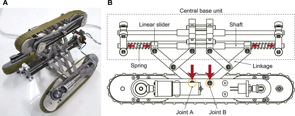
FIGURE 1. A mechanical model of our proposed in-pipe robot with underactuated parallelogram modules [(A): overview picture, (B): pantograph contractile mechanism].
2.2 Underactuated parallelogram crawler module
The contractile mechanism always presses each module against the inner wall of the pipe with a spring, thus it is difficult to shrink the robot body when an obstacle is encountered or the diameter of the pipe is reduced. Therefore, in this study, we developed a new shape-shifting mechanism called “underactuated parallelogram crawler” and installed it in three modules to address this problem. In general, active flipper arms and shape-shifting functions have often been deployed independently to solve such obstacle adaptation problems. However, in an environment that is restricted in space, such as in pipelines, adding actuators is a major barrier to downsizing. In this research, the power for moving forward and backward is utilized for shifting the crawler shape by an underactuated mechanism.
There are three reasons why a parallelogram shape is adopted for the crawler mechanism.
1. When the crawler shape is shifted to a parallelogram, the mainframe of the crawler is lifted, and a force can be generated in the direction to shrink the contractile mechanism.
2. Even if the crawler shape is shifted to a parallelogram, the total belt circumference length is constant, thus, there is no need to add a new mechanism to maintain the belt tension.
3. Usually, in-pipe robots need to have the same function not only when moving forward but also when moving backward. A parallelogram can achieve anterior-posterior symmetric shape as illustrated in Figure 2. By using this symmetric shape-shifting function, even if it is difficult to pivot-turn, it can achieve the same transformation in the reverse direction by simply moving backward without changing the robot orientation.
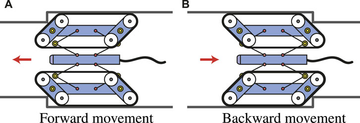
FIGURE 2. Similar mobility for anterior-posterior symmetric transformation [(A): forward movement, (B): backward movement].
Figure 3 shows the cross-sectional view of a single underactuated parallelogram crawler. First, the motor is fixed to the outside of the crawler frame, and the power is transmitted to the differential mechanism in the front flipper via the bevel gear. With this differential mechanism, the power is transmitted to the drive pulley at the tip and the rotation of the flippers at the same time. The detailed principle is described later in the next subsection.
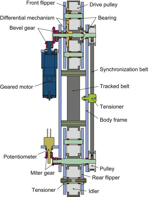
FIGURE 3. A CAD model of an underactuated parallelogram crawler module (cross-sectional view).
It is necessary to synchronize the rotation of the front and rear flippers to make the crawler parallelogram. In the real world, a parallel link mechanism is often used to synchronize the front and rear rotations, as seen in crank-bars of steam locomotives. However, during the normal driving in our case, the front and rear flippers are aligned in a straight line. For this reason, the flipper must be rotated from a singular posture, and the forward and backward movements are not uniquely determined (Ye et al., 2012). To solve this problem, the output of the front flipper is also transmitted to the rear flipper via a timing belt attached to the opposite side of the motor. As a result, the axes of the front and rear flippers are synchronized. Optionally, a potentiometer can be attached to the rear flipper to estimate the rotation angle of the flippers.
In conventional underactuated crawler robots, a reduction gear such as a planetary gear mechanism is often used to generate the differential movement (underactuated movement) (Lan et al., 2007; Kim et al., 2010; Quan and Ma, 2011; Wang et al., 2016). However, a large reduction gear cannot be used because the inner space of the pipe is limited. Therefore, in this study, a simple differential mechanism using a couple of spur gears is adopted (Li et al., 2010).
2.3 Pseudo multiple degrees of freedom by utilizing external forces
Figure 4 shows the principle of the proposed underactuated parallelogram crawler as well as two modes of the normal driving and parallelogram. In the normal driving mode (Figure 4A), the front and rear flippers are horizontal because the crawler module is pressed against the inner wall of the pipe by the pantograph mechanism. In this state, the power is transmitted to the drive pulley at the front tip, and the crawler can move forward and backward.
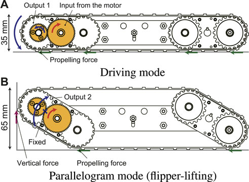
FIGURE 4. The two modes of the differential mechanism [(A): driving mode, (B): parallelogram mode].
On the other hand, when the crawler is in contact with an obstacle and the robot movement is intercepted, the drive pulley cannot be rotated around its own axis. As a result, it revolutes around the input gear and the crawler shape is shifted to a parallelogram as shown in Figure 4B.
In addition, since the pulley’s drive force is always generated even in contact with the obstacle, a vertically upward force is applied to the contact point of the crawler front portion. This force has an effect of assisting the rotation of the flipper. The flippers can be lifted without using a high reduction ratio thanks to this assistance. In other words, if the force acting on the crawler’s contact point can generate a moment in the direction of assisting the rotation of the flipper, the desired operation can be performed even at a low reduction ratio. Therefore, the number of gears can be greatly reduced compared with conventional underactuated crawler robots. This will lead to downsizing and lightweight.
Many existing crawler robots used in outdoor environments often improve obstacle-adaptability by preparing a tilt angle of the tracked-belt. However, since the size is limited in pipelines, a method of shifting the robot’s shape depending on the environment is more effective. Furthermore, when an unexpected external force is applied to the crawler during the travel, it can be mitigated using the rotation of the flipper. This can reduce the impact on the motor (Quan and Ma, 2011).
When the crawler contacts with the obstacle, the flippers rotate inward, and the shape is shifted to a parallelogram. However, if the resistance continues to be applied to the tracked-belt, the flippers keep rotating infinitely in the opposite direction to that of travel. Eventually, the robot cannot overcome the obstacle. To solve this, when the flipper is rotated to 30°, stopper pins are attached to prevent further rotation (Figure 5). If the motor continues to rotate in this state, the crawler can move forward by driving the tracked-belt while maintaining the parallelogram.
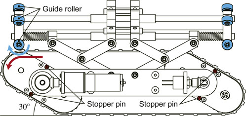
FIGURE 5. Stopper pins used to limit the rotational angle of the flippers and guide rollers to guarantee smooth motion of the tracked belt.
When the contractile mechanism shrinks while keeping a parallelogram shape of the crawler, the tracked-belt contacts with the central portion of the robot. Thus, a large resistance is generated that interrupts the robot movement. To reduce this resistance, guide rollers are attached to the front and rear tips of the robot as shown in Figure 5.
3 Quasi-static model
Since the underactuated mechanism divides one input into two outputs simultaneously, the distribution ratio of the two outputs greatly affects the performance. This differential phenomenon is often expressed using a branch tube as shown in Figure 6 (Lan et al., 2007). In normal driving mode, only the drive pulley rotates and the flipper must be stationary. In other words, the actual torque transmitted to the drive pulley τact.p must be larger than τreq.p. In the same manner, the actual torque transmitted to the flipper τact.f must be less than τreq.f. On the other hand, in parallelogram mode, the drive pulley should stop and the flipper must rotate. Therefore, τact.p must be smaller than τreq.p, and τact.f must be greater than τreq.f.
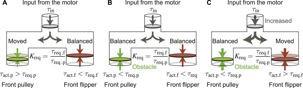
FIGURE 6. Branch pipe models for torque distribution: (A) Driving mode, (B) Between driving mode and parallelogram mode, (C) Parallelogram mode.
Here, the ratio between the torque required to rotate the drive pulley and the one required to lift the flipper and the actual output ratio are defined as follows, respectively.
in the driving mode, both of the following two conditions should be satisfied.
in the parallelogram mode, the following two conditions should be satisfied in a similar way.
therefore, Kact should meet the following conditions.
Since τreq.p and τreq.f change depending on the environment the crawler encounters, these values are derived based on static models as shown in Figure 7A–C, respectively.
The static model is simplified by dividing the crawler into three rigid bodies: a front flipper, a rear flipper, and a body frame. To generalize, the crawler moves on the inner wall of the pipe tilted by α, and the front flipper is in contact with the step. The rotation axes of the front and rear flippers are at the respective centers and are fixed to both ends of the main body frame. In addition, since the axes of these flippers are synchronized by the timing belt, the torque required to rotate the rear flipper τreq.r interact with the front flipper as inner torque. The motor input torque τreq.f is applied to the front flipper, and its reaction is applied to the body frame.
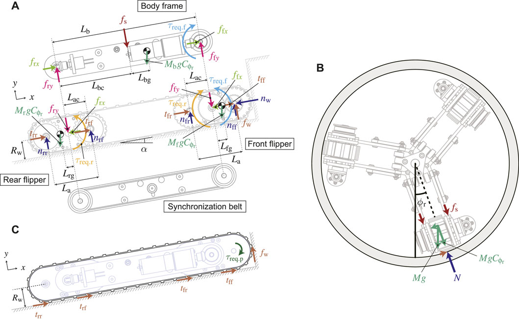
FIGURE 7. Possible external forces acting on the underactuated parallelogram crawler [(A): forces of each rigid body, (B): forces of the tracked belt, (C): forces in the cross-sectional view].
Since the three crawler modules are arranged radially as shown in Figure 7B, the direction of gravity applied to the modules changes depending on the roll-posture of the robot. Therefore, each gravitational force acting in the radial direction of the pipe is calculated by
3.1 Torque for lifting the flippers
From Figure 7A, the torque required to lift the flipper can be obtained from the balance of external forces and moments acting on the three rigid bodies (front flipper, rear flipper, and body frame). This is because the required torque means a boundary value to break down the force balance. Considering the balance of forces in the x and y-axes and the moment around the rotation axis of the flipper, the static balance equations of the front flipper can be obtained by
in the same way, the static balance equations of the body frame can be derived by
the static balance equations of the rear flipper are obtained by
They are basic equations for force and moment balance, thus, the applied external forces vary depending on the situation where the crawler is placed. Different torque conditions in two situations, the normal driving mode and the parallelogram mode, are obtained, respectively.
3.1.1 Torque for lifting the flippers in the normal driving mode
In the normal driving mode, the tip of the crawler does not touch the obstacle. Therefore, fw = nw = 0 is obtained. Assuming that the flipper is slightly raised, tff = trf = nff = nrf = 0. Substituting them into the above Eqs 8–10, the equations of equilibrium for the front flipper can be derived below:
in a similar way, substituting the above conditions into Eqs 14–16, the equations of equilibrium for the rear flipper can be obtained.
the equations of equilibrium for the body frame are the same as Eqs 11–13.
From Eqs 11, 17, 20, the sum of the tangential force of the crawler is
from Eqs 12, 18, 21, the sum of the normal forces is
Now, substituting Eqs 23, 24 into the sum of Eqs 19, 22, the torque to lift both front and rear flippers in the normal driving mode τreq.f can be calculated as follows:
The first term depends on the gravitational force and the spring force of the contractile mechanism, meaning that these forces need to be overcome to lift the flippers. The second term depends on the inclination angle of the inner wall of the pipe α. The larger this angle is, the smaller the torque required to lift the flipper, thus, the sign is negative. The third term depends on the position of the center of gravity of the front and rear flippers. The farther the position of the center of gravity is from the rotational axis of the arm, the more susceptible it is to that effect. In an actual robot, there is an initial resistance that is generated by the mechanical frictions such as the forces applied to the bearings and shafts due to the tension of the belt, and the inertia, etc., which influence each other in a complicated manner. Therefore, this initial resistance is collectively defined as τi here.
3.1.2 Torque for lifting the flippers in the parallelogram mode
In the parallelogram mode, it is assumed that the flippers are slightly lifted, thus, tff = trf = nff = nrf = 0 can be obtained. However, the tip of the crawler is in contact with the obstacle. Therefore, fw ≠ nw ≠ 0, and the equations for the force-moment balance of the front flipper are given below:
The equations of equillibrium for the rear flipper are the same as Eqs 20–22 as well as that for the body frame are the same as Eqs 11–13. From Eqs 11, 20, 26, the sum of the tangential force of the crawler is derived by
from Eqs 12, 21, 27, the sum of the normal forces applying on the crawler is
When the crawler contacts an obstacle and cannot move forward further, the tracked-belt slips. Since sliding friction force generates at this moment, the following relationship can be derived using the sliding friction coefficient μs:
substituting Eqs 29, 30, 33 into the sum of Eqs 22, 28, τreq.f can be calculated by
from Eqs 29–33, the normal force that disturbs the crawler movement nw is obtained by
In a similar way as Eq. 25, the first term in Eq. 34 depends on the gravitational force and the spring force of the contractile mechanism. The second term depends on the inclination angle of the inner wall of the pipe α, and the larger this angle is, the torque necessary to lift the flippers reduces. The third term also depends on the position of the center of gravity of the front and rear flippers, similar to Eq. 25. The fourth term depends on the upward force applying between the crawler and the obstacle fw, and this force assists the rotation of the flippers. τi is also defined as the initial resistance.
3.2 Torque for rotating the pulley of the tracked-belt
The torque for rotating the pulley at the tip τreq.p is generated from the torque for rotating the front flipper τreq.f transmitted via the spur gear. It can be assumed that this torque is balanced with the forces applying along the crawler’s belt as shown in Figure 7C. Considering the initial resistance τi in the same manner, τreq.p is given by
as mentioned in the section of the torques for lifting the flipper in the normal driving mode and the parallelogram mode, the torque for rotating the pulley at the tip τreq.p varies between two modes. Therefore, they are derived in each mode as follows.
3.2.1 Torque for rotating the pulley in the normal driving mode
In the normal driving mode, fw = nw = 0 because the tip of the crawler does not contact the obstacle. Therefore, τreq.p can be obtained by removing fw from Eq. 36.
eliminating nw from the sum of Eqs 8, 11, 14 and substituting them into Eq. 37, τreq.p can be obtained by
3.2.2 Torque for rotating the pulley in the parallelogram mode
On the other hand, in the parallelogram mode, the tip of the crawler contacts the obstacle, and the front and rear flippers are lifted. Therefore, fw ≠ nw ≠ 0 and tff = trf = 0. As a result, τreq.p is given by
substituting Eqs 29, 33 into Eq. 39, the torque for rotating the pulley in the parallelogram mode τreq.p can be derived by
nw can be obtained from Eq. 35.
4 Gear ratio design
τreq.p, τreq.f obtained by the static analysis, and their output ratio K are given by Eqs 25, 38 in the normal driving mode and Eq. 34, 40 in the parallelogram mode. The parameters of each rigid body used in the analysis are: Mf [kg] = 0.13, Mb [kg] = 0.20, Mr [kg] = 0.12, g [m/s2] = 9.8, Rw [mm] = 20, La [mm] = 46, and Lb [mm] = 150. Since the rear flipper of the crawler and the mainframe have a symmetrical structure, Lbg = Lrg = 0 is assumed. Also, the center of gravity of the front flipper is moved only by the gear of the tip pulley, and this influence is small, thus, Lfg = 0. For the sliding friction coefficient μs, 0.4 of the general polyurethane belt used for crawlers and vinyl chloride used for pipes is used.
For the initial resistance τi, the value when the real crawler was idling with no load, which is calculated by the following equation using the motor current i at no-load rotation, torque constant Kτ, and reduction ratio Kratio.
the current value is the measured value i = 0.054 A, the torque constant is Kτ = 8.83 Nmm/A from the motor specifications, and the reduction ratio is the actual value Kratio = 231 is used. Based on them, τi = 106.4 Nmm is obtained.
4.1 Influence of the expanding force of the contractile mechanism fs and determination of the spring stiffness
When the crawler module is located on the upper inner wall of the pipe, the contractile mechanism needs to press the crawler with a larger force against gravity. Therefore, the influence of the expanding pressing force fs of the contractile mechanism is calculated under the conditions of α = 0 and ϕr = 180°. Figure 8A, B show the effects of fs in the normal driving mode and that of fs in the parallelogram mode, respectively. When fs is 4.4 N or less, τreq.p and τreq.f are both less than τi. This means that the crawler moves away from the inner surface of the pipe, in other words, fs should be at least 4.4 N.
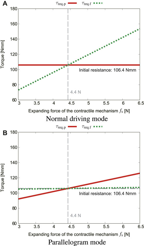
FIGURE 8. Effects of the expanding force fs, where μs = 0.4, α = 0, ϕr = 180° [(A): normal driving mode, (B): parallelogram mode].
The expansion force of the contractile mechanism is influenced by the spring force sp. The relationship between those two forces can be obtained by the following equation with the tangent function, referring to the literature (Kwon and Yi, 2012).
in our case, the actual natural length of the spring is 55 mm, and it shrinks to 53 mm when the robot enters the straight pipe. Therefore, the spring force is given by sp = Ks(55 − 53) (k denotes the spring stiffness). In the straight pipe, ψ = 70°, and Ks = 0.5 N/mm was selected because fs is approximately 5.5 N, which satisfies the condition of 4.4 N or higher.
4.2 Influence of the robot roll angle ϕr
Figure 9A shows how the roll angle of the robot ϕr influences τreq.p, τreq.f, and output ratio Kreq in the normal driving mode. For fs, the above-mentioned value of 5.5 N was substituted. In a similar way, Figure 9B shows how ϕr influences τreq.p, τreq.f, and output ratio Kreq in the parallelogram mode. In order to make the robot perform the ideal motion, the actual output ratio Kact should be smaller than Kreq in the normal driving mode but greater than that in the parallelogram mode according to Eq. 7. Combining these two graphs, the output ratio should be within the range of 0.98 < Kact < 1.23 to fit with all roll angles range ϕr. When Kact < 0.98, even if the robot contacts with an obstacle, the flipper cannot be lifted and keeps slipping. When 1.36 > Kact, the flipper is lifted even in the normal driving mode.
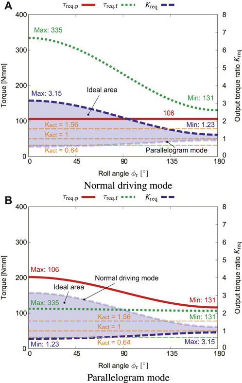
FIGURE 9. Effect of the roll angle ϕr, where μs = 0.4, fs = 5.5 N, α = 0 [(A): normal driving mode, (B): parallelogram mode].
4.3 Influence of the initial resistance τi
Figure 10A plots how the initial resistance τi influences τreq.p, τreq.f, and output ratio Kreq in the normal driving mode. From Figure 9, the rolling angle at the most severe condition (Kreq range is the narrowest) ϕr = 180° was used. Figure 10B shows how τi influences τreq.p, τreq.f, and output ratio Kreq in the parallelogram mode.
The results revealed that the initial resistance τi should be small to increase the range of Kreq. On the other hand, as the initial resistance increases, the values of K both approach one, thus the range of Kreq is very narrow. If structures that cause a large initial resistance are installed, the output ratio must be set to one, which leads to a decrease in the option of the reduction ratio.
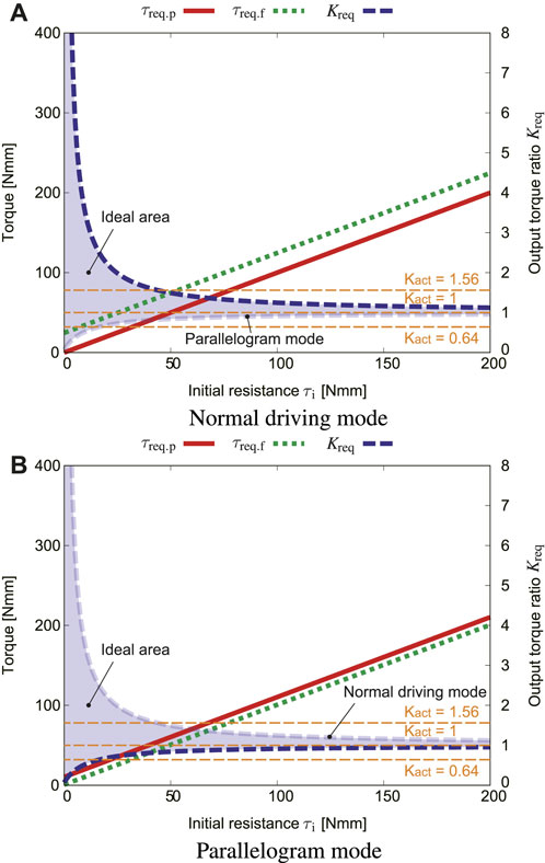
FIGURE 10. Effect of the initial friction τi, where μs = 0.4, fs = 5.5 N, α = 0, ϕr = 180° [(A): normal driving mode, (B): parallelogram mode].
4.4 Influence of the pipe slope angle α
Figure 11A shows how the pipe slope angle α influences τreq.p, τreq.f, and output ratio Kreq in the normal driving mode. In the normal driving mode, τreq.p is maximum where α = 90°, which corresponds to the vertical pipe. The torque τreq.f for lifting the flipper is inversely proportional to α. This means that as α increases, gravity helps the flippers rotate.
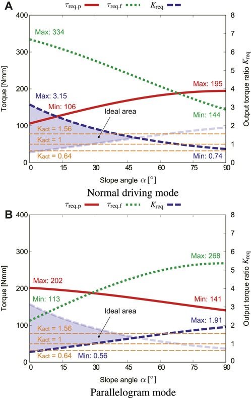
FIGURE 11. Effect of the slope angle α, where μs = 0.4, fs = 5.5 N, ϕr = 0 [(A): normal driving mode, (B): parallelogram mode].
Figure 11B shows how α influences τreq.p, τreq.f, and output ratio Kreq in the parallelogram mode. Since Eq. 34 is a function that includes both sin α and cos α, τreq.f is maximum near α = 60°. The two Kreq curves intersect at about α = 47°. This means that if α exceeds 47°, the flipper will be lifted even in the normal driving mode. However, in reality, when the flipper is lifted, the contractile mechanism is also shrunk, then fs increases, and the flipper stops rotating and restarts the movement.
The ideal range of Kact gradually narrows as α increases. In this study, the actual output ratio is set to three variations: Kact = 1.56, Kact = 1, and Kact = 0.64 to fit with as wide range of α as possible. This is the value where the gear teeth number ratio is 56 : 36, 46 : 46, and 36 : 56, respectively. The output ratio Kact = 1.56 exceeds Kreq at around ϕr = 135° as illustrated in Figure 9. This means that the flipper may be rotated when the crawler is flipped and located at the top inner surface of the pipe. However, this will not influence the forward and backward movement of the robot, because it can move even with the parallelogram shape.
4.5 Influence of the sliding frictional coefficient μs
The sliding friction coefficient μs is not taken into account in the normal driving mode. Therefore, only the influence of μs in the parallelogram mode is described here. Figure 12 shows how μs influences τreq.p, τreq.f, and output ratio Kreq in the parallelogram mode. The torque for lifting the flipper τreq.f has a negative value when μs exceeds around 0.8. This means that if μs is sufficient, the torque for rotating the flipper is not needed, and the crawler can shift its shape by only using the pulley rotation. When the sliding friction coefficient μs is less than around 0.2, Kact needs to be larger than 1.56, and the flipper cannot be lifted at this state because the crawler slips. The larger the sliding friction coefficient μs, the wider the ideal range of Kact. With this condition, the crawler can perform the adaptive movement to the environment even with a small output ratio.
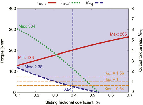
FIGURE 12. Effect of the sliding frictional coefficient μs in the parallelogram mode, where fs = 5.5 N, ϕr = 0, α = 0.
The rated torque of the geared motor used for the proposed robot is 1,230 Nmm. The maximum value of the torque required to rotate the flipper τreq.f is 335 Nmm according to Figures 9, 11. This satisfies the requirement. However, considering further safety factor, the torque of the motor is amplified twice by the bevel gear.
5 Experiments
5.1 Experimental setup
Adaptability of the proposed robot with underactuated parallelogaram modules was tested in a straight stepped pipe as shown in Figure 13. A standard constricted pipe called decreser was connected with two straight pipes with different diamiter; 202 mm (8 in) and 154 mm (6 in). The influence of the pipe slope angle α can be also examined by using a slope adjustment mechanism.
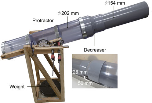
FIGURE 13. Experimental setup of a straight stepped pipe with a slope adjustment mechanism.
To verify the performance with different gear ratio (output ratio Kact), three types of teeth number conbination: Kact = 1.56, Kact = 1, and Kact = 0.64 are prepared as depicted in Figure 14.
Each teeth number of two spur gears needs to satisfy the following condition:
where Nf, Np, D, and Nmod denote the teeth number of the input (flipper) and output (pulley) gears, distance between two gear centers, and the gear module (the ratio of the reference diameter of the gear divided by the number of teeth), respectively. In our case, D = 23 mm and Nmod = 0.5, thus, the sum of Nf and Np should keep 92.
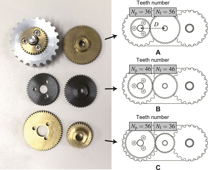
FIGURE 14. Three types of gear ratio: (A) Speed multiplication Kact = 1.56, (B) No speed change Kact = 1, (C) Speed reduction Kact = 0.64.
Three motor drivers combining an ESCON 50/5 (Maxon group ag, Sachseln, Switzerland) and a microcontroller were fabricated for smooth experimentation, and control commands were given to each of them to keep the rotation speed at 40 rpm via CAN communication. The control commands were given via a graphical user interface (GUI) created with Visual Studio C#.
5.2 Experimental results
The experiment was conducted three times each with the following five combinations: α = 0 & ϕr = 0, α = 0 & ϕr = 180°, α = 45° & ϕr = 0, α = 45° & ϕr = 180°, and α = 90°. Upper table in Table 1 lists the success number in each trial where Ks = 0.5 N/mm.
From the experiment, it was found that the robot had the best step-adaptability when the output ratio was Kact = 0.64. It indicates that it is better to distribute the torque to the pulley than to the flipper. This result differs from the analysis in the previous section. However, the crawler module was able to deform into a parallelogram shape upon contacting the step in all results. The front half of the robot then slid to a stop as it entered the next narrow pipe (6 in). In all cases, the reason for the inability to travel to the narrow pipe was that the propulsive force of the crawler module was not sufficient to shurink the contractile mechanism.

TABLE 1. Experimental results where Ks = 0.5 N/mm (upper) and Ks = 0.3 N/mm (lower).
On the other hand, experiments were also conducted for Ks = 0.3 N/mm, which had been excluded because the analysis resulted the difficulty of adaptation to the step. The results of the experiment are listed in the lower table of Table 1. Overall, the results with Kact = 0.64 tended to be better, and in all cases the crawler module was able to shift its shape into a parallelogram. However, the performance at Kact = 1.56 was slightly better than that in the experiments with Ks = 0.3 N/mm.
Overall, the results with Kact = 0.64 tended to be better, and in all cases the crawler module was able to shift its shape into a parallelogram. However, the performance at Kact = 1.56 was slightly better than that in the experiments with Ks = 0.3 N/mm.
Some problems were found as a result of the experiments in the stepped pipe. For example, even when the robot adapted from a large-diameter to a small-diameter pipe, it sometimes did not return to its initial pose after returning from a small-diameter to a large-diameter pipe. Pressing the three crawler modules against the wall by a spring force large enough for the mass of the central part of the robot could solve this problem. However, the weight of the central part of the robot must be drastically reduced and the motor power must be increased due to the increased spring force.
On the other hands, even if the robot did not return to the original pose, it can be solved by controlling only each crawler module individually. For example, if only the contractile mechanism of the lower module shrinks, only that module will shift to parallelogram shape when only the lower one is driven and the other two upper modules are not. After repeating this operation several times, the pose will return to its original state (straightened). This is a disadvantage of the underactuated mechanism, but it is also an advantage of requiring fewer motors.
6 Conclusion
This paper proposes an environmental adaptation in-pipe robot with underactuated parallelogram crawlers. Without using additional motors and sensors, each crawler module can shift its body shape to a parallelogram to adapt to obstacles. The shape-shifting movement is generated by a simple differential mechanism of a pair of spur gears. However, whether the crawler moves forward or shifts the body shape depends on the gear ratio of the differential mechanism. To design the gear ratio, the required output ratio of the pulley to rotate and the flipper to lift up in the normal driving and parallelogram modes was analyzed quasi-statically. The influences of the roll angle of the robot, the initial resistance of the crawler, the slope angle of the pipe, and the frictional coefficient were also simulated. To examine the adaptability performance depending on the gear ratio, experiments in a tilted stepped pipe with a developed in-pipe robot were performed.
The robot successfully shifted its crawler’s shape to parallelogram only with our simulated output ratio, which implies that our quasi-static analysis is valid. In addition to the shape-shifting, the propulsive force for the contraction of the contractile mechanism and friction coefficient of the tracked belt were also found to be important for the adaptation to the stepped pipe. However, in tilted pipe experiments, the robot could not overcome the step, while it could climb the straight section against the gravity. This is because the unexpected uneven posture of the contractile mechanism was generated. One possible solution could be changing the stiffness of the contractile mechanism, but the gear ratio should be also redesigned again to match with this. Expanding the distance between two pantographs at each crawler module may make the contractile mechanism stiff against the external force. This would also solve the uneven posture problem.
Data availability statement
The datasets presented in this article are not readily available because Raw data cannot be published and shared. Requests to access the datasets should be directed to a2Frb2dhd2FAZmMucml0c3VtZWkuYWMuanA=.
Author contributions
AK designed and built the robot and wrote the paper. SM advised him on research and writing papers. All authors contributed to the article and approved the submitted version.
Acknowledgments
We would like to express our sincere thanks to Mr. Ferdinand Fukui Peper and Mr. Yosuke Imamura, graduate students, who helped us with the experiments.
Conflict of interest
The authors declare that the research was conducted in the absence of any commercial or financial relationships that could be construed as a potential conflict of interest.
Publisher’s note
All claims expressed in this article are solely those of the authors and do not necessarily represent those of their affiliated organizations, or those of the publisher, the editors and the reviewers. Any product that may be evaluated in this article, or claim that may be made by its manufacturer, is not guaranteed or endorsed by the publisher.
References
Birkenhofer, C., Hoffmeister, M., Zollner, J., and Dillmann, R. (2005). “Compliant motion of a multi-segmented inspection robot,” in Proceedings of the 2005 IEEE/RSJ International Conference on Intelligent Robots and Systems, Edmonton, AB, Canada, August 2005 (IEEE), 2632–2637.
Debenest, P., Guarnieri, M., and Hirose, S. (2014). “Pipetron series-robots for pipe inspection,” in Proceedings of the 2014 3rd international conference on applied robotics for the power industry, Foz do Iguacu, Brazil, October 2014 (IEEE), 1–6.
Dertien, E., Foumashi, M. M., Pulles, K., and Stramigioli, S. (2014). “Design of a robot for in-pipe inspection using omnidirectional wheels and active stabilization,” in Proceedings of the 2014 IEEE International Conference on Robotics and Automation (ICRA), Hong Kong, China, June 2014 (IEEE), 5121–5126.
Dertien, E., Stramigioli, S., and Pulles, K. (2011). “Development of an inspection robot for small diameter gas distribution mains,” in Proceedings of the 2011 IEEE International Conference on Robotics and Automation, Shanghai, China, May 2011 (IEEE), 5044–5049.
Fjerdingen, S. A., Liljebäck, P., and Transeth, A. A. (2009). “A snake-like robot for internal inspection of complex pipe structures (piko),” in Proceedings of the 2009 IEEE/RSJ international conference on intelligent robots and systems, St. Louis, MO, USA, October 2009 (IEEE), 5665–5671.
Hirose, S., Ohno, H., Mitsui, T., and Suyama, K. (1999). “Design of in-pipe inspection vehicles for/spl phi/25,/spl phi/50,/spl phi/150 pipes,” in Proceedings of the 1999 IEEE International Conference on Robotics and Automation (Cat. No. 99CH36288C), Detroit, MI, USA, May 1999 (IEEE), 2309–2314.
Inazawa, M., Takemori, T., Tanaka, M., and Matsuno, F. (2021). Unified approach to the motion design for a snake robot negotiating complicated pipe structures. Front. Robotics AI 8, 629368. doi:10.3389/frobt.2021.629368
Kakogawa, A., Hirose, C., and Ma, S. (2022a). “A standards-based pipeline route drawing system using a towed sensing unit,” in Proceedings of the 2022 IEEE/RSJ International Conference on Intelligent Robots and Systems (IROS), Kyoto, Japan, October 2022 (IEEE), 7167–7173.
Kakogawa, A., Komurasaki, Y., and Ma, S. (2019). Shadow-based operation assistant for a pipeline-inspection robot using a variance value of the image histogram. J. Robotics Mechatronics 31, 772–780. doi:10.20965/jrm.2019.p0772
Kakogawa, A., and Ma, S. (2018). Design of a multilink-articulated wheeled pipeline inspection robot using only passive elastic joints. Adv. Robot. 32, 37–50. doi:10.1080/01691864.2017.1393348
Kakogawa, A., and Ma, S. (2013). “Design of an underactuated parallelogram crawler module for an in-pipe robot,” in Proceedings of the 2013 IEEE International Conference on Robotics and Biomimetics (ROBIO), Shenzhen, China, December 2013 (IEEE), 1324–1329.
Kakogawa, A., Ma, S., and Hirose, S. (2014). “An in-pipe robot with underactuated parallelogram crawler modules,” in Proceedings of the 2014 IEEE International Conference on Robotics and Automation (ICRA), Hong Kong, China, June 2014 (IEEE), 1687–1692.
Kakogawa, A., and Ma, S. (2012). Stiffness design of springs for a screw drive in-pipe robot to pass through curved pipes and vertical straight pipes. Adv. Robot. 26, 253–276. doi:10.1163/156855311x614554
Kakogawa, A., Murata, K., and Ma, S. (2022b). Automatic T-branch travel of an articulated wheeled in-pipe inspection robot using joint angle response to environmental changes. IEEE Trans. Industrial Electron. 70, 7041–7050. doi:10.1109/tie.2022.3201301
Kim, B.-S., Vu, Q.-H., Song, J.-B., and Yim, C.-H. (2010a). Novel design of a small field robot with multi-active crawlers capable of autonomous stair climbing. J. Mech. Sci. Technol. 24, 343–350. doi:10.1007/s12206-009-1108-7
Kim, J.-H., Sharma, G., and Iyengar, S. S. (2010b). “Famper: A fully autonomous mobile robot for pipeline exploration,” in Proceedings of the 2010 IEEE International Conference on Industrial Technology, Via del Mar, Chile, March 2010 (IEEE), 517–523.
Kwon, Y.-S., and Yi, B.-J. (2012). Design and motion planning of a two-module collaborative indoor pipeline inspection robot. IEEE Trans. Robotics 28, 681–696. doi:10.1109/tro.2012.2183049
Lan, G., Ma, S., Inoue, K., and Hamamatsu, Y. (2007). Development of a novel crawler mechanism with polymorphic locomotion. Adv. Robot. 21, 421–440. doi:10.1163/156855307780132045
Li, Z., Ma, S., Li, B., Wang, M., and Wang, Y. (2010). “Design and basic experiments of a transformable wheel-track robot with self-adaptive mobile mechanism,” in Proceedings of the 2010 IEEE/RSJ International Conference on Intelligent Robots and Systems, Taipei, Taiwan, October 2010 (IEEE), 1334–1339.
Liu, Y., Bi, Q., Dai, X., Song, R., Zhao, J., and Li, Y. (2022). Ticbot: development of a tensegrity-based in-pipe crawling robot. IEEE Trans. Industrial Electron. 70, 8184–8193. doi:10.1109/tie.2022.3224131
Nishimura, T., Kakogawa, A., and Ma, S. (2012). “Pathway selection mechanism of a screw drive in-pipe robot in t-branches,” in Proceedings of the 2012 IEEE international conference on automation science and engineering (CASE), Seoul, Korea (South), August 2012 (IEEE), 612–617.
Park, J., Hyun, D., Cho, W.-H., Kim, T.-H., and Yang, H.-S. (2010). Normal-force control for an in-pipe robot according to the inclination of pipelines. IEEE Trans. Industrial Electron. 58, 5304–5310. doi:10.1109/tie.2010.2095392
Pfotzer, L., Ruehl, S., Heppner, G., Roennau, A., and Dillmann, R. (2014). “Kairo 3: A modular reconfigurable robot for search and rescue field missions,” in Proceedings of the 2014 IEEE International Conference on Robotics and Biomimetics (ROBIO 2014), Bali, Indonesia, December 2014 (IEEE), 205–210.
Pfotzer, L., Staehler, M., Hermann, A., Roennau, A., and Dillmann, R. (2015). “Kairo 3: moving over stairs & unknown obstacles with reconfigurable snake-like robots,” in Proceedings of the 2015 European Conference on Mobile Robots (ECMR), Lincoln, UK, September 2015 (IEEE), 1–6.
Quan, Q., and Ma, S. (2011). Development of a modular crawler for tracked robots. Adv. Robot. 25, 1839–1849. doi:10.1163/016918611x584712
Roh, S.-g., and Choi, H. R. (2005). Differential-drive in-pipe robot for moving inside urban gas pipelines. IEEE Trans. robotics 21, 1–17. doi:10.1109/tro.2004.838000
Roh, S.-g., Kim, D. W., Lee, J.-S., Moon, H., and Choi, H. R. (2009). In-pipe robot based on selective drive mechanism. Int. J. Control, Automation Syst. 7, 105–112. doi:10.1007/s12555-009-0113-z
Rome, E., Hertzberg, J., Kirchner, F., Licht, U., and Christaller, T. (1999). Towards autonomous sewer robots: the makro project. Urban Water 1, 57–70. doi:10.1016/s1462-0758(99)00012-6
Schempf, H., Mutschler, E., Gavaert, A., Skoptsov, G., and Crowley, W. (2010). Visual and nondestructive evaluation inspection of live gas mains using the explorertm family of pipe robots. J. Field Robotics 27, 217–249. doi:10.1002/rob.20330
Streich, H., and Adria, O. (2004). “Software approach for the autonomous inspection robot makro,” in Proceedings of the IEEE International Conference on Robotics and Automation, 2004. Proceedings. ICRA '04. 2004, New Orleans, LA, USA, May 2004, 3411–3416.
Suryavanshi, K., Vadapalli, R., Vucha, R., Sarkar, A., and Krishna, K. M. (2020). “Omnidirectional tractable three module robot,” in Proceedings of the 2020 IEEE International Conference on Robotics and Automation (ICRA), Paris, France, August 2020 (IEEE), 9315–9321.
Tugeumwolachot, T., Seki, H., Tsuji, T., and Hiramitsu, T. (2022). “Development of a multi-dof cutting tool with a foldable supporter for compact in-pipe robot,” in Proceedings of the 2022 International Conference on Mechatronics and Automation, Guilin, Guangxi, China, August 2022 (IEEE), 587–592.
Wang, Q., Quan, Q., Deng, Z., and Hou, X. (2016). An underactuated robotic arm based on differential gears for capturing moving targets: analysis and design. J. Mech. Robotics 8. doi:10.1115/1.4032811
Ye, C., Lv, G., Ma, S., and Ni, H. (2012). “Development of a variable parallelogram tracked mobile robot,” in Proceedings of the 2012 IEEE International Conference on Robotics and Biomimetics (ROBIO), Guangzhou, China, December 2012 (IEEE), 2156–2160.
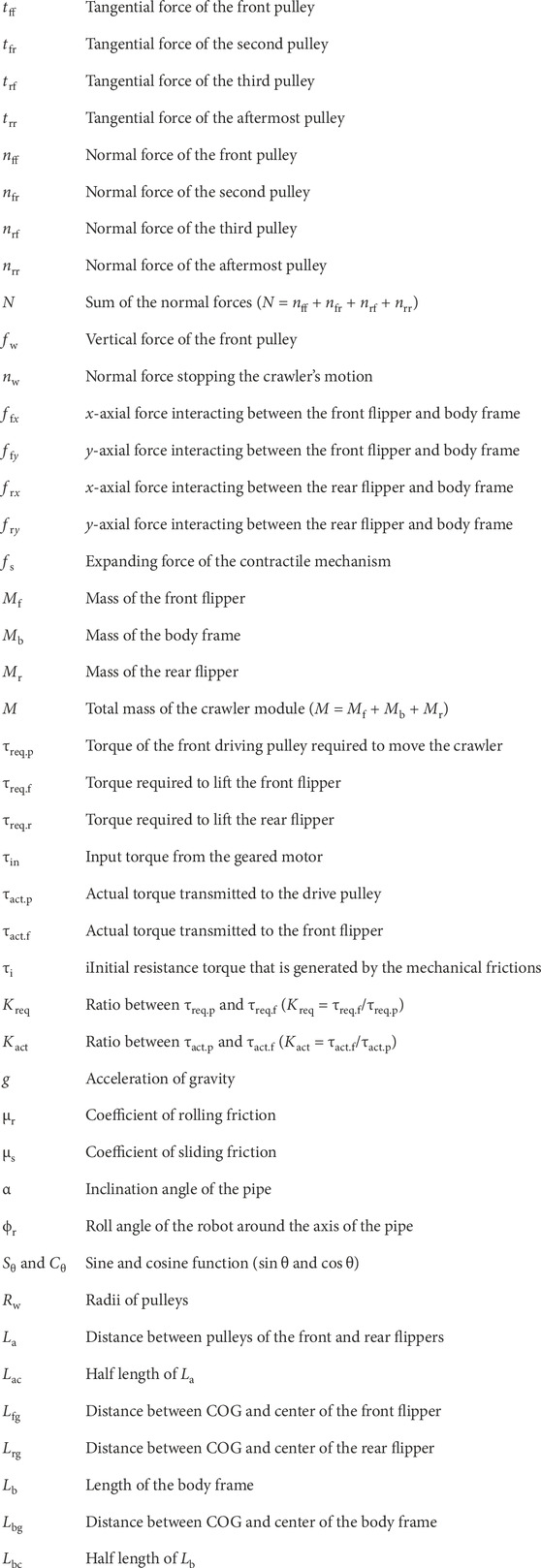
Nomenclature
Keywords: underactuation, differential mechanism, environmental adaptation mechanism, in-pipe robot, crawler module
Citation: Kakogawa A and Ma S (2023) Effect of underactuated parallelogram shape-shifting for environmental adaptation movement of a three modular in-pipe robot. Front. Robot. AI 10:1234835. doi: 10.3389/frobt.2023.1234835
Received: 05 June 2023; Accepted: 05 September 2023;
Published: 21 September 2023.
Edited by:
Tanveer Saleh, International Islamic University Malaysia, MalaysiaReviewed by:
Md Raisuddin Khan, International Islamic University Malaysia, MalaysiaTao Huang, James Cook University, Australia
Copyright © 2023 Kakogawa and Ma. This is an open-access article distributed under the terms of the Creative Commons Attribution License (CC BY). The use, distribution or reproduction in other forums is permitted, provided the original author(s) and the copyright owner(s) are credited and that the original publication in this journal is cited, in accordance with accepted academic practice. No use, distribution or reproduction is permitted which does not comply with these terms.
*Correspondence: Atsushi Kakogawa, a2Frb2dhd2FAZmMucml0c3VtZWkuYWMuanA=