 Lubomir Prech
 Yuri Y. Ruzhin2
- 1Faculty of Mathematics and Physics, Charles University, Prague, Czechia
- 2Pushkov Institute of Terrestrial Magnetism, Ionosphere and Radiowave Propagation (IZMIRAN), Russian Academy of Sciences, Troitsk, Russia
The APEX mother-daughter project (Active Plasma EXperiments) was launched into an elliptical polar orbit (440–3,080 km) in December 1991. It consisted of the main Russian Interkosmos–25 (IK–25) satellite and the Czech MAGION–3 subsatellite, both with international scientific payloads. The mission used intensive modulated electron beam emissions and xenon plasma or neutral releases from the main satellite for studies of dynamic processes in the magnetosphere and upper ionosphere. Its main scientific objectives were to simulate an artificial aurora and to study optical and radio emissions from the aurora region, and to investigate the dynamics and relaxation of modulated electron and plasma jets, artificially injected into the ionospheric plasma. The experiments studied the Critical Ionization Velocity phenomenon and a diamagnetic cavity formation during the xenon releases, local and distant effects of the electron beam injection, spacecraft charging and potential balance, and plasma-wave interactions during the artificial emissions. Attempts were performed to utilize the modulated electron beam as an active transmitting antenna in the space. The theory of ballistic wave propagation across plasma barrier was tested in a joint active experiment with the Dushanbe ionospheric heater facility. In the paper, we give a short overview of the IK–25/MAGION–3 scientific instrumentation and methodology of experiments with artificial beam injections and we provide a review of the main APEX active experiments results, many of which have been published only in the Russian language so far. From a historical 25-years-long perspective, we try to put the results of the APEX experiments into the context of other active experiments in the space plasma.
1. Introduction
Active experiments in space plasma utilize many different agents to disturb the ionospheric or magnetospheric environment and to stimulate many variable but rather rare natural phenomena under controlled conditions (Raitt, 1995). The response is then studied in order to get information on natural space structures (e.g., electron beam tracing of magnetospheric or ionospheric electric and magnetic fields), to use artificially produced phenomena as models of natural ones (artificial aurora etc.) or to verify mechanisms which would explain some physical processes (e.g., beam—plasma interactions, wave generation, photochemical reactions) when the relevant physical conditions cannot be achieved in laboratory experiments. Some active experiments have close connections to technology. They are motivated by problems in the design and reliability of the artificial satellites or they help to develop new power generators or propulsion methods.
Since 1960s, tens of active charged particle beam experiments (e.g., Winckler, 1980; Grandal, 1982; Podgorny, 1982; Neubert and Banks, 1992; Raitt, 1995), in space have been performed, the motivations behind these experiments ranging from investigations of charge neutralization processes in the plasma medium near the beam source to probing conditions on remote sections of geomagnetic field lines (Winckler, 1980). A lot of interesting experimental results was obtained aboard the U.S. space shuttles (e.g., Burch, 1986), few other satellites were devoted to active experiments in space plasma at altitudes starting in ionosphere to solar wind. During last two decades their frequency has decreased and the scientific community has turned more to theoretical studies, computer simulations, or data reanalysis in this field. New science mission concepts (e.g., MacDonald et al., 2012) may return active space plasma experiment to the foreground of scientific interest.
The topic of this overview paper—the APEX project satellite pair—had relatively unique orbit among the active experiment spacecraft as it will be described later. It had extensive scientific payload and ambitious science plans. Although it is more than 26 years since the launch now, new original research articles still profit from the collected data. We bring an overview of the active APEX experiments and their results, while many other interesting results of passive ionospheric observations (often based on the two-point satellite measurements rare in that era) are out of the scope of this paper. The overview should not be considered as a complete list of references to the APEX project related literature, some results were originally published in Russian and only later appeared in a Russian translation version of the journal or in other English language journals or proceedings and for such cases we usually cite just one reference.
The review is organized to several sections. The first one comprises introduction to the APEX project, its origin, scientific goals, and a short summary of the scientific instruments onboard the two satellites of the project. Comments to the active experiment planning and telemetry issues are included here as well. The result overview section starts with analysis of the main satellite charging during the passive observations and active experiments with the electron beam injection neutralized by neutral xenon/xenon plasma releases or during the xenon plasma releases itself. Overview of the neutral xenon releases related to the critical ionization velocity (CIV) phenomenon processes follows. Next part is devoted the beam-plasma interaction, discussing the plasma environment in a vicinity of the main satellite during the beam injections, diamagnetic cavity formation, electron pitch-angle distributions, and generation of ELF/VLF and HF waves. Distant injection effects as observed from the subsatellite at distances of hundreds of kilometers are summarized in the next subsection. The last part briefly covers the ionospheric heating experiments in which the main APEX satellite participated. Summary and concluding remarks close the article.
2. APEX Project
The international experiment APEX in frame of the former INTERCOSMOS science program was suggested by IZMIRAN—the Pushkov Institute of Terrestrial Magnetism, Ionosphere, and Radio Wave Propagation of the Russian Academy of Sciences, Troitsk, Russia, and the Geophysical Institute of Czechoslovak Academy of Sciences, Prague, Czech Republic (GFI, the group is affiliated to the Institute of Atmospheric Physics of Czech Academy of Sciences today) in mid 1980's. The project followed previous Soviet/international active experiments with sounding rockets and satellites (Stereotop, PORCUPINE, Trigger, Zarnitsa, G–60–S, ARAKS, ACTIVE) (Cambou et al., 1975, 1980; Dokukin et al., 1981; Haerendel and Sagdeev, 1981; Sagdeev et al., 1981; Managadze et al., 1988; Klos et al., 1998), this time in a new mother-daughter configuration and with wide international payload (Russia, Ukraine, Czechoslovakia, Poland, Rumania, Bulgaria, Hungary, eastern Germany). The name of the Interkosmos programme project APEX is abbreviated from from words “Active Plasma EXperiments.” The core of the project were active experiments with injection of electron and (or) plasma beams from a board of the low Earth's orbit (LEO) satellite with simultaneous registration of the phenomena, produced by interaction of injected beams with background plasma.
Essentially important peculiarity of the project were synchronous measurements of the basic physical parameters of the environment, of the beam and generated fields on two space-separated vehicles—the main satellite APEX Interkosmos–25 and its subsatellite MAGION–3 (Figure 1). The independent subsatellite with small gas trusters for orbit correction carried out simultaneous measurements on various mutual distances (from 10 m up to 1,000–2,000 km), at different areas of beam-disturbed environment, at different zones of the Earth's magnetosphere and ionosphere. The “boomerang” maneuvers of MAGION–3 were performed few times: it was pushed forward along the orbit and returned backward to main satellite, so MAGION-3 escaped from the main IK–25 up to few hundreds km and came back at distance about 0.4 km (Figure 2). An important part of the program were investigations of natural and human-made phenomena in a passive mode. The presence of two spacecrafts, equipped with practically equivalent complexes of the scientific equipment, enabled not only to carry out diverse researches of the ionosphere and the bottom magnetosphere, but also to distinguish spatial and temporal structures of the observable phenomena. A nearly polar orbit allowed to carry out research in auroral area. The complex program of “under satellite” ground observation and experiments included standard geophysical monitoring and special programs with ionospheric heating facilities.
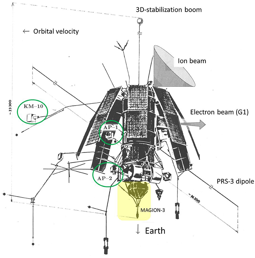
Figure 1. IK–25 deployed (before MAGION–3 separation, its launch position highlighted in yellow). Positions of the KM–10, AP–1, and AP–2 particle sensors, the PRS–3 dipole antenna, and the electron/ion injection directions are indicated. (Adapted from Prech, 1995).
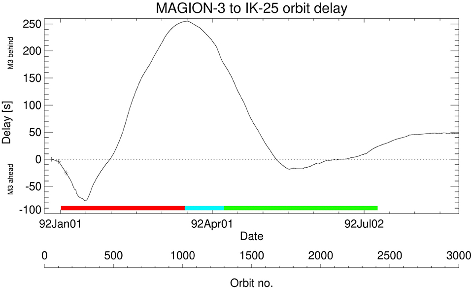
Figure 2. MAGION–3 to IK–25 in-orbit delay. The delay absolute minimum corresponds to ~580 km distance ahead, the absolute maximum to ~1, 900 km distance behind. The red bar denotes the season where both UEM and UPM injections were performed, later only the experiments with the UPM injector were done—blue with xenon plasma, green— neutral xenon releases only.
Both spacecrafts, the main IK–25 and its subsatellite MAGION–3, were launched on an elliptical orbit with apogee of 3,080 km and perigee of 440 km, with the 82.5° inclination of the orbital plane on December 18, 1991 from the Russian space base Plesetsk. Orbital period was ~2 hours.
2.1. APEX Scientific Goals
The scientific goals of the project as described in Oraevsky et al. (1992) and Oraevsky and Triska (1993) are summarized below:
• Study of the dynamics and relaxation of modulated electron and plasma jets artificially injected into near-Earth plasma.
• Study of the low-frequency and MHD waves generation by heavy ions in the ionosphere.
• Determination of the radio emission generated by modulated beams of charged particles.
• Search for non-linear wave structures of the electromagnetic soliton type in a disturbed plasma environment.
• Study of the process of neutralization and dynamics of spacecraft charging.
• Study of the nature of the electrodynamic relationship between electromagnetic waves in the magnetosphere and ionosphere.
• Study of optical and radio emission in the auroral region.
• Passive mode observations—ionospheric plasma profiles under different conditions, auroral precipitation dynamics, mapping, and dynamics of polar cusps etc.
The APEX programme principal investigator (PI) was Viktor N. Oraevsky (1935–2006) from IZMIRAN, the MAGION subsatellite programme founder and PI was Pavel Triska (1931–2018) from GFI.
2.2. Scientific Payload
The main satellite IK–25 design was based on the AUOS–Z–AP–IK spacecraft bus aboard of the Tsyklon–3 rocket launcher, both produced by the KB Yuzhnoe, Dnepropetrovsk, Ukraine. The MAGION–3 subsatellite platform was designed and produced by the Geophysical Institute in Prague.
Both satellites were equipped with a complex scientific payload developed in a wide international cooperation. The particle, fields, wave, and supporting diagnostics are enumerated in Tables 1, 2.
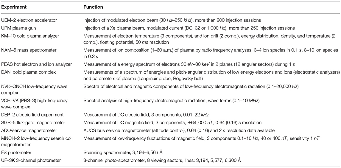
Table 1. IK–25 scientific payload (Dokukin, 1992).
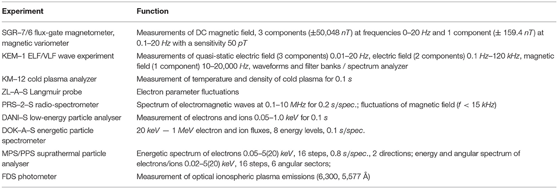
Table 2. MAGION–3 scientific payload (Triska et al., 1990).
2.2.1. IK–25 Short Description
The AUOS–Z bus consisted of a pressurized cylinder of about 1 m diameter and height ~2m. Eight solar panels (~12m2) were deployed 30° away (petal-like). The IK–25 satellite was gravitationally stabilized, its vertical position being kept by a spherical weight on about 20 m long boom (see Figure 1). The spacecraft utilized the 28V power bus with the + pole commutation. Spacecraft charging characteristics (see section 3.1.1) suggested the solar panels were partially exposed to the ionospheric plasma. The current collection through the solar panel area in contact with the plasma depends on the panel design and technology—individual solar cell interconnects and edges exposure, coverglass conductivity/presence of a grounded transparent conductive coating, potential bias between the solar cells/cell interconnect layout etc., but such details of the AUOS–Z bus are unknown to us. For an example of the recent solar panel current collection modeling (see, e.g., Hess et al., 2016).
The UEM–2 electron gun consisted of two electron injectors G1 (oriented opposite to the satellite orbital velocity vector) and G2 (inclined toward the Earth). Utilizing a magnetic deflector, the G2 injector could turn the electron beam to the G1 beam orientation (see Figure 3) that corresponded to the injection pitch angles 50−80° for typical active parts of the IK–25 orbit. The electron acceleration voltage could reach 8–10 kV (unstabilized) with the peak current ~30, 70, or 100 mA. The initial beam width was 4 mm at the output aperture. The electron gun could run in two basic modulation modes:
• Fixed frequencies: F40K (40 kHz), F15.6K, F976—all 2 μs pulses, F3906, F30.5 (32 μs pulses)
• Sweeping frequency: S250 (30.5 Hz–250 kHz, 2 μs pulses, 1 DC + 11 frequency steps—1 s each) and S15.6 (30.5 Hz–15.6 kHz, 32 μs pulses, 1 DC + 11 frequency steps—1 s each), basic cycle length 23 s
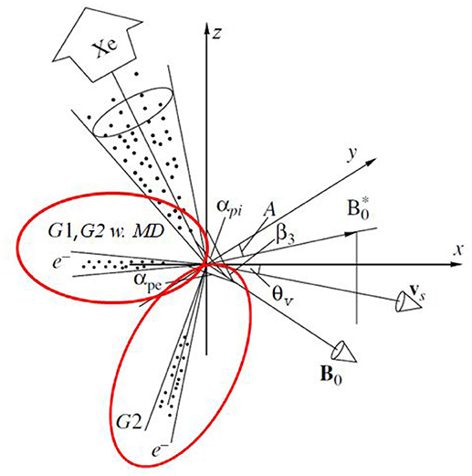
Figure 3. Injection directions, orientation angles of the magnetic field B0 and velocity vs in the satellite frame of reference xyz; the z axis is directed from the Earth. “Xe”—UPM xenon plasma/neutral gas release cone, G1 (G2 with the magnetic deflector MD) and G2 (without the deflector) denote possible electron gun UEM injections. αpi, αpe mark the ion and electron injection pitch angles. (Reprinted from Baranets et al., 1999, with permission from Elsevier).
The UPM xenon plasma injector utilized a stationary plasma thruster (SPT) of Hall type (with close electron drift and extended acceleration zone) (Artsimovich et al., 1974) similar as used in the PORCUPINE experiment (Haerendel and Sagdeev, 1981). The xenon plasma was released to a 60° wide cone oriented ~45° from the zenith direction as illustrated in Figure 3. The ion energy reached 200–250 eV, ion temperature ~50eV, ion current 2 A (1019 ions/s), ~100% ionization degree. As only xenon ions can leave the main discharge and accelerator section of the thruster, electrons from a supplementary xenon discharge (two external hollow cathodes LaB6 installed, electron temperature ~2eV) initiated the main discharge and simultaneously neutralized the xenon plasma beam injected to the space. The injector could work in these modes:
• Neutral xenon release, ~3mg/s,
• DC xenon plasma emission–F0
• Modulated xenon plasma emission (almost 100% current modulation)–F1000 (1 kHz; 62, 125, 250, and 500 Hz modulation frequencies were other options)
The UPM cycle consisted of ~35–45 s preheating interval (with neutral xenon release lasting ~5–6s, further denoted as Xe-A, and the hollow cathode emission, further as Xe-B) and one or several intervals of ~100s plasma injection followed by ~50s neutral xenon release only (Xe-A/Xe-B). Housekeeping and science data revealed additional ~0.12Hz current modulation (up to 20%) due to unknown internal/external feedback. Only the neutral xenon gas was released during certain orbits as the ionization voltage was not applied due to technical reasons (Oraevskii et al., 1999).
Mean injection current profiles of the UEM–2 and UPM devices are displayed in Figure 4. The UEM–2 and UPM working cycles were not synchronized, one active experiment lasted usually ~3–5 min. Emission current and acceleration voltage (housekeeping) data were averaged over 0.32 or 0.08 s intervals. The UEM–2 and KM–10 floating probe telemetry data indicate a low intensity electron beam was also present during the one-second gaps between the modulated beam injections and in time between the S250 modulation sequences.
Figure 4. Mean injection current profiles for different beam modulation modes of the UEM–2 and UPM injectors. Top two panels—UEM–2 modes S250 and S15.6; bottom three panels—UPM DC mode F0, modulated mode F1000, and neutral xenon gas release. (Adapted from Prech, 1995).
The KM–10 cold plasma monitor (also described in Afonin et al., 1994) consisted of the sensor and main electronics boxes. The sensor box was mounted on a ~0.8m boom in front of the solar panels in the ram direction, out of the xenon plasma/electron beams. Its box with a conductive surface was electrically isolated from the spacecraft and kept near the ionospheric plasma potential actively by means of monitoring a floating potential (Φp) of one of its 7 probes (0.16, 0.64/0.2 s time resolution for the RTS/STO–AP telemetries, respectively, −10 to +16V range). Ion density Ni, temperature Tix, Tiz (planar retarding potential analyzers), ion drift in the YZ plane, and electron temperatures Tex, Tey, Tez (planar probes with RF bias) were the output parameters of this instrument.
The PEAS hot plasma spectrometer (Nemecek et al., 1993, 1997) measured energy-angular distributions in two planes (2 double toroidal analyzers, 12 angular sectors each, electron/positive ion sweeps alternated). Its default operational mode provided one 16-energy level spectrum (50 eV–22 keV) of electrons and ions in 2.6 s (STO–AP), the sampling was not synchronized with the UEM–2/UPM data sampling. The AP–1 sensor block was mounted on a one-meter boom ahead of spacecraft (45° to XZ plane as depicted in Figure 1), the AP–2 sensor block was assembled ~0.5m above the nadir spacecraft side (XY plane), the two block distance was ~3m. Registered particle pitch-angles (PA) distributions were computed using the ADO magnetometer. The block orientation corresponded to wide PA-range distributions by AP–1 (AP–2) in auroral (equatorial) regions, respectively. During flight, several sector channels got noisy and were excluded from further data processing.
The onboard wave measurements were performed using the PRS–3 (VCH–VK complex) plasma radio spectrometer, which represented a receiver with an input signal sensitivity of 0.5 μV and a stepped tuning in the 0.1–10.0 MHz frequency range (Izhovkina et al., 2009). The frequency tuning step was 25, 50, 100 kHz, the bandwidth at a receiver input was 15 kHz, and the dynamic range of input signal level variations was 80 dB. An electric dipole antenna of the VCH–VK complex with a total length of 15 m, parallel to the Earth's surface, was used as a device sensor (Figure 1).
The low-frequency wave instrument NVK–ONCH registered magnetic field spectrum in the range 8–969 Hz and amplitudes at fixed frequencies 9.6 and 15.0 kHz (Oraevsky et al., 2001). Measurements of the sensitive flux-gate magnetometer SGR–5 and the spacecraft service magnetometer were used to assess a level of magnetic field fluctuations at lowest frequencies. Quasi-steady electric field 0.1–10 Hz components and VLF electric field spectra were measured by a system of double electric probes connected to inputs of the DEP–2 instrument and the NVK-ONCH wave complex (Baranets et al., 2007).
2.2.2. MAGION–3 Short Description
The size of the object was 0.85 × 0.60 m diameter (2 m with deployed booms), its weight was 52 kg. The orbital speed could be corrected using pressurized neutral gas (nozzles parallel/antiparallel with the satellite axis). The satellite axis was oriented approximately along the local geomagnetic field (built-in permanent magnet 30 Am2 with week dumping) (Triska et al., 1990).
The suprathermal particle spectrometer MPS/PPS was a simplified version of the PEAS instrument (Nemecek et al., 1994). It measured energy distribution of electron and ions in one half-plane containing the satellite main axis, divided to 6 angular sectors (SEA–A and SEA–B toroidal-cut analyzers, 25° width). The system was complemented by two narrow field-of-view electron energy analyzers MP–A and MP–B (parallel/antiparallel to the satellite axis, respectively) to obtain a full-range electron pitch-angle distribution (8 channels with 30° spacing).
The energetic particle sensor DOK–A–S registered energetic electron and proton fluxes parallel and perpendicular to the satellite axis using two pairs of silicon detectors (Prech et al., 2002; Baranets et al., 2007).
The wave experiment provided spectra of two electric and one magnetic field components in ELF/VLF ranges (Triska et al., 1990; Baranets et al., 2007). Waveforms of selected electric/magnetic components up to 60 kHz (2–3 × 8 Hz−20kHz or narrow-band) could be directly transmitted to ground. The PRS–2–S radio-spectrometer provided spectra with Δf 15 or 50 kHz resolution in the HF frequency range 0.1–10 MHz (one electric field component, 3m length dipole) (Rothkaehl and Klos, 1996).
2.3. Active Experiment Methodology
The MAGION–3 was separated on December 28, 1991 from the main satellite and drifted away with a speed ~5 km/day. Several tens of orbit corrections were made to keep the mother-daughter relative distance within range −580 to +1, 900 km. The in-orbit MAGION–3 to IK–25 delay evolution is depicted in Figure 2. Color bars in this figure mark different campaigns of active experiments, planning of which was affected by the electron and ion injectors working status. About 200 active experiments with electron and plasma injections in various configurations were performed till July 1992 within the satellite relative distance 70–500 km. Planned experiments in near (>10m to 0.4 km) and mid-range (~1–10 km) zones could not be performed for technical reasons. Two-point passive measurements at distances 100–2,000 km continued till the MAGION–3 end-of-life in August 1992. Ionospheric investigations by IK–25 lasted till July 1993.
The IK–25 satellite was controlled from Soviet telemetry stations and selected scientific data were delivered to ground via its primary telemetry channel (RTS), mostly from its on-board telemetry memory with downloads once per day but real-time telemetry sessions were also started frequently in the regions of satellite visibility to allow better data time resolution. Except the active experiment devices and diagnostic equipment IK–25 also included a complementary telemetry system STO-AP developed by teams from Hungary, former USSR, Poland, and Czech Republic. The system STO–AP provided an interface for the scientific instruments, management of operation modes, preliminary processing of the scientific information, independent control of onboard experiments, formation of the TM frames and transfer of the telemetry information to the ground-based stations at Czech Republic (Panska Ves), Russia (Troitsk, Apatity, Tarusa), and Germany. STO–AP enabled higher volume/better time resolution of science data mostly during real-time telemetry sessions lasting about 10 min (memory replay sessions with limited data volume were also sporadically performed). Drawback of this approach was the IK–25 visibility regions from the RTS and STO–AP reception stations did not fully overlap (resulting many active experiments controlled via RTS were not fully covered by scientific data routed via STO–AP). Beside it, the STO–AP telemetry channel (137/400 MHz bands) was often affected during strong xenon plasma injections (short drop-outs and wide data gaps were present during such sessions). The limited total telemetry capacity necessitated trade-offs in the scientific instruments operational modes and their resolution, during some orbits not a complete parameter set could be studied.
The MAGION–3 daughter satellite was controlled and scientific data transmitted via the STO telemetry to the Panska Ves observatory (Czech Republic) mostly during real-time sessions as its onboard data memory volume was limited (4 MB). For this reason the satellite pair visibility also affected the simultaneous data coverage of active experiments as performed from the main IK–25 satellite, especially during periods of larger spacecraft separation.
The Panska Ves visibility requirement made the altitude, invariant latitude (INL)/L–shell, magnetic local time (MLT) parameters of the APEX active experiments bound. As the active experiments were run above the north hemisphere, downward electron injections during day were toward the north magnetic pole (near mirror point in dense ionoshere below) and upward electron injections (during night) were directed toward the south magnetic pole (distant mirror point behind the rarefied top ionoshere/magnetosphere). This brings difficulties to separate some physical parameter dependencies. The electron and plasma injectors onboard IK–25 had many working/modulation modes and the elliptical orbit of the satellite pair allowed performing the active experiments for different ionospheric parameters. Ideally, a certain injection configuration should be repeated several times under different ambient conditions, but in reality only one usable dataset was captured for many configurations.
Despite these technical difficulties a rich database of observational data from active experiments of the APEX project was collected and many interesting scientific results were published.
3. Result Overview
3.1. Spacecraft Charging and Neutralization During Active Emissions
Beside the complex IK–25 design geometry the evaluation of the spacecraft (s/c) charging properties was complicated also by other factors. The IK–25 body was painted and its surface was assumed equipotential but the conductivity was not characterized in publicly available data. The scientific payload was painted or covered by multi-layer insulation (MLI) and connected to the spacecraft ground and the surface again assumed equipotential (not guaranteed). Solar panel surfaces probably were not equipotential—the positive potential end was probably exposed to the ionospheric plasma (dayside effects on the satellite potential). Also, after the end of all injections the spacecraft potential return to its “quiet” level immediately during night, but with a time constant of few minutes during day. A full charge balance analysis has also to consider the stabilization boom/weight at ~20m distance. The electrical current across the boom was not monitored, unfortunately.
The KM–10 sensor box (placed ahead of the spacecraft in the ram direction) was kept floating near the ionospheric plasma potential (δΦ ~ −0.2to−0.7 V for Te ~ 0.1−0.3eV, not considering photocurrent/suprathermal electrons). The KM–10 floating probe potential Φp (normally positive against s/c) was widely used as a spacecraft potential proxy (Φs ≈ −Φp+δΦ), but its design range ±90V is doubtful (−10to+16V limitation was observed in practice). The KM–10 data time resolution (0.2 s) and UEM/UPM injection data (0.32/0.08 s resolution) unfortunately do not allow to study transient charging phenomena during the injections on/off or detail profiles for individual sub-millisecond electron injection pulses. As the Debye length near the apogee (~10V, 104cm−3) is approximately 1 m, the KM–10 might not be always out of the spacecraft Debye sheath. Also, this spacecraft potential proxy is considered unreliable when the KM–10 ion density Ni drops to its lower limit (~108m−3). The parameter reliability was discussed in more details in Prech (1995).
During the active experiments with electron injections, the secondary electron emission from the spacecraft surface due to hot electron collection (return currents) probably also affected the spacecraft charge balance. Up today no detail and realistic IK–25 charging model is publicly available. A simplified model is discussed by Zilavy et al. (2003).
3.1.1. IK–25 Potential Outside of Active Experiments
Prech et al. (1999) investigated the “quiet time” behavior of the IK–25 spacecraft properties. Figure 5A depicts a potential difference between the KM–10 floating probe and the satellite (Φp) as a function of the altitude. The data were collected during intervals preceding the electron/plasma injections and the satellite potential can change for several volts depending on the part of the orbit (with changing the altitude, ambient plasma density, and electron temperature), the satellite always charges negatively. The dayside/nightside orbits split the observations to two branches. The night branch (the satellite was in the Earth's shadow) is a rising function of the altitude which was explained with the electron temperature also rising with the altitude. Figure 5B shows the same data as a function of the ion density Ni measured by the KM–10 device. The higher potentials (more negative s/c charging Φs) on the dayside branch are assumed due to the solar panels connected through a small resistance to the ambient plasma at low altitudes. This resistance is a function of density and the effect gradually disappears at altitudes above 2,500 km or densities below 109m−3.
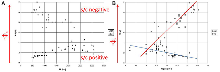
Figure 5. IK–25 spacecraft potential outside of active experiment intervals. The plots show the potential difference between the KM–10 floating probe and the spacecraft body as a function of the altitude (A) and the ambient plasma density (B). The spacecraft is charged negatively for positive KM–10 floating potentials. (Reprinted from Prech et al., 1999, with permission from Elsevier).
3.1.2. IK–25 Potential During the Electron Beam Injections With Xenon Plasma Neutralization
The IK–25 spacecraft charging during the electron beam injections with the xenon plasma neutralization can be summarized to following conclusions (Prech, 1995, 2002; Prech et al., 1995, 1999; Nemecek et al., 1997):
• For ambient plasma densities the electron beam charge was well neutralized, Φs < 15V for S250 and F40K modes peak currents, KM–10 density Ni measured ahead of the spacecraft was not further increased during the xenon injections.
• For ambient plasma densities and the xenon plasma release during day kept the KM–10 ram density and the electron beam charge was well-neutralized, the neutralization appeared even better during night, the KM–10 ram density and the spacecraft potential relaxed to its “quiet” level (for example see Figure 6B).
• For lower ambient plasma densities during neutral xenon gas / hollow cathode releases (Xe-A/Xe-B) the spacecraft is charged to more than +20V against its “quite” level. The KM–10 floating potential reached a negative saturation or after shortly negative excursion it traveled to positive saturation and as such it could not be used as a reliable IK–25 charging monitor (Figure 6B). As accelerated cold ionospheric electrons were not registered by the PEAS spectrometer, the spacecraft potential was within limits ~20V < Φs < ~50V.
• During the modulated electron beam injection (S250), when Φp was not in saturation, ~1s positive pulses in the spacecraft potential were observed (rising/falling edges < 0.2s)—see e.g., Figure 6A. Their amplitude increased with the mean electron pulse current level until it reached the unmodulated (F40K) levels. The amplitude was larger during Xe-B mode than with the main xenon plasma injection showing worse electron beam neutralization in this mode.
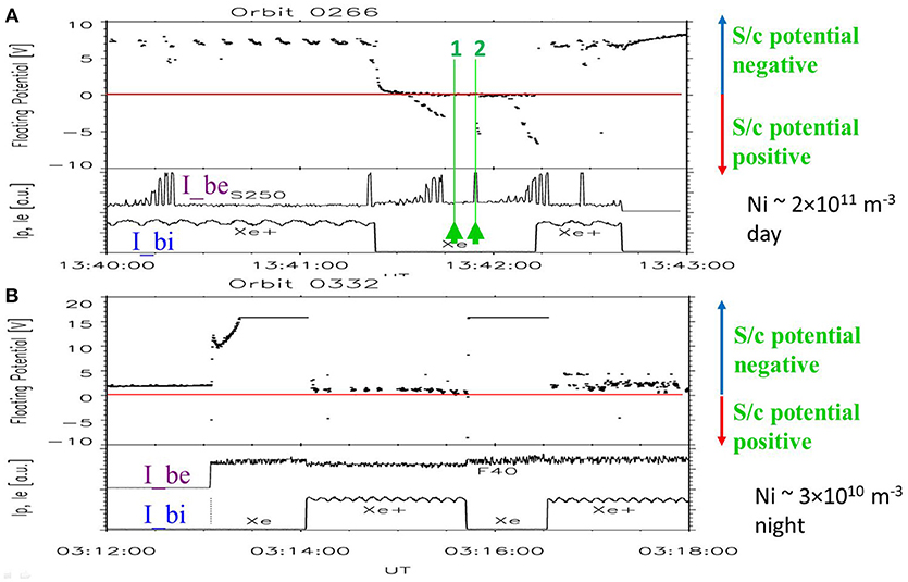
Figure 6. Examples of the IK–25 spacecraft potential behavior during electron beam injections. The plots show the KM–10 floating probe potential, mean UEM electron beam and UPM plasma injector currents: (A) Orbit 0266—dayside modulated electron beam (S250 mode, G1 injector) with xenon gas/plasma neutralization (F0 mode), green vertical lines assigned 1 and 2 mark instants with the UEM beam base current and UEM beam maximum current (DC pulse); (B) Orbit 0332—nightside electron beam injection (F40K mode, G2 injector with magnetic deflector) with xenon gas/plasma neutralization (F0 mode). (Reprinted from Prech et al., 1995, with permission from Elsevier).
3.1.3. IK–25 Potential During the Xenon Plasma Injections
The IK–25 spacecraft potential behavior during the UPM neutral gas releases and xenon plasma injections (UEM not active) was studied by Prech et al. (1999), further examples and discussion are contained in Prech (1995, 2002). It was found that the release of the neutral xenon alone did not affect the spacecraft potential under conditions of the APEX experiment. The change of the spacecraft potential dFP induced by the release of the xenon plasma was up to ~±10V (e.g., Figures 7A,B). Such a change was considered reasonable, as the temperature of the plasma in the injector output was about 50 eV, sharply decreasing with the distance from the spacecraft due to adiabatic expansion of the xenon plasma cloud. A dense conducting cloud (plasma contactor) created by the released plasma behind the spacecraft was expected to effectively collect electrons from the ambient plasma. Being partly in the spacecraft wake the cloud contribution to the ion current is found smaller. The dimension of this cloud was expected comparable with the dimensions of the “diamagnetic phase” of the plasma cloud expansion proposed by Hausler et al. (1986).
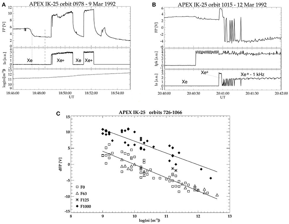
Figure 7. Examples of the IK–25 spacecraft potential behavior during the xenon plasma injections. (A) (Night DC injection F0 mode at ~440 km altitude) shows the KM–10 floating probe potential, the mean UPM ion current, and the ambient plasma density (KM–10). (B) (Dayside DC/1 kHz injection F1000 mode at ~2, 900 km altitude) depicts the KM–10 floating probe potential, the UPM hollow cathode current, and the mean UPM ion current (in both panels Xe stands for the neutral xenon release intervals, Xe+ for the xenon plasma injections). (C) Change of the spacecraft potential during the xenon plasma releases as a function of the ambient plasma density for different UPM modulation modes. (Reprinted from Prech et al., 1999, with permission from Elsevier).
The electron current collected by the cloud should rise linearly with ambient plasma density, but this rising current causes an increase in the negative spacecraft potential. The result was the observed linear relationship between logNi and dFP (Figure 7C). The collected electron current as the difference between those electrons actually collected and those leaving the plasma cloud was found either positive or negative. If the number of electrons collected from the ambient plasma is higher than the number leaving the cloud then the spacecraft potential change vs. “quiet” level dFP is negative, otherwise it is positive. Altitude, ambient plasma temperature, and day/night dependencies were found small for this effect.
The DC xenon plasma emission was studied in a simple model of a planar floating probe, spherical satellite, and plasma cloud by Zilavy et al. (2003). The authors stress the importance of suprathermal electron tail and ion mass composition (affecting the H+, O+ ion ram energy) of ionospheric plasma for charge balance. The model can explain the spacecraft potential change of both polarities suggesting the ionospheric O+ ions are less effectively collected by the plasma cloud due to their higher ram kinetic energy.
3.2. Neutral Xenon Release Experiments
During the xenon plasma injection experiments of the APEX programme, about 20 experiments were performed when the UPM device worked uniquely in the mode of neutral xenon gas release. Additional experiments included simultaneous injections of electron beam and neutral xenon. Under conditions of the experiment the kinetic energy of the xenon atoms motion relative to the ionospheric plasma (~25–40eV) exceeded the xenon first ionization potential (~12.1eV), so the necessary condition of the anomalous ionization was satisfied. The neutral xenon releases occurred over the full altitude range 450–3,000 km and variety of experimental conditions (geomagnetic field strength, ambient plasma density, injection angle vs. magnetic field direction, illumination etc.) allowing comparison with other experiments.
Oraevskii et al. (1999) and Choueiri et al. (2001) analyzed the influence of the neutral xenon releases to spectra of high-frequency plasma turbulence, accelerated electron spectra, and spectra of electric field fluctuations near lower-hybrid resonance. They also studied dependence on angle between the magnetic field and the gas injection direction. The experimental data show the ambient plasma response to the neutral gas injection including electron temperature and anisotropy increase and amplification of wave activity practically over full range of registered frequencies. Theoretical considerations of these papers are consistent with the observed data. Although only small flows of neutral xenon gas (~3mg/s) were released during several minute lasting intervals, due to its collisional interaction with the background ionospheric plasma a sufficient number of “seed” energetic ions was created so as the CIV-related electron heating could be observed. Newly created xenon ions by charge exchange collisions, electron impact ionization, photo-ionization, and scattering of ionospheric plasma ions were considered in their analyses. The calculated ionization yield smaller than 1% corresponds to not observable changes of plasma density. Ion-ion lower-hybrid wave instability was expected to reach distances 3–100 m. In the spacecraft reference system these waves have a perpedicular to the magnetic field phase velocity component in the range of reflected ion speeds 0–7 km/s, but their group velocity is directed almost parallel to the magnetic field. For this reason the waves can reach the spacecraft and be detected. Unfortunately, the proper frequency band diagnostic was not operating, but simultaneous narrow- and wide-band HF emissions in the range 3–10 MHz during dayside xenon gas emissions with pitch angles 85–115° were observed. Intensification of HF wave activity was not observed during nightside emissions (pitch angles 57–71°). The wave frequency bands were flat and did not evolve along the orbit (magnetic field strength). The authors think that the observed waves could be a symptom of turbulent fluctuations connected with the instability, but without a theoretical explanation. According to the authors, it is possible that the presence of the solar flux and not the emission pitch angle is the controlling parameter for the observed effects. In such a case, the role of the solar flux in affecting HF wideband activity through intermediary effects such as plasma enhancement due to photoionization may be worthy of investigation.
3.3. Beam-Plasma Interaction
3.3.1. Hot Electron Pitch-Angle Distributions During Electron Beam Injections
Plasma environment in the vicinity of the IK–25 spacecraft and return currents during the UEM electron beam injections were studied in Prech (1995), Nemecek et al. (1997), and Prech et al. (1998) using the PEAS electron and ion spectra with following conclusions:
• Hot electrons as a part of the return current were registered by both the AP–1 and AP–2 sensors with energies peaking between ~102 and 103eV, electrons were preferentially accelerated perpendicular to the magnetic field. The acceleration mechanism was weaker during simultaneous xenon plasma release.
• The hot electron flux and energy increased with the mean primary beam current, but the PEAS time resolution did not allow to observe any resonance effects depending on the electron beam modulation frequency.
• The energy/pitch-angle distributions allowed to distinguish several electron populations attributed to accelerated ambient plasma electrons (at lower energies) and scattered beam electrons (few keV energies). No electrons with energies accelerated above the primary beam energy were found in the PEAS spectra.
• Hot suprathermal electrons constituting a part of the return currents arrived with comparable fluxes from directions parallel and antiparallel to the magnetic field, i.e., not only from the area behind the spacecraft disturbed by the injected beam but also from the ahead region that could be affected only by the return currents and secondary products of the beam-plasma interaction.
• The energy and flux of these electrons decreased for pitch angles closer to parallel/antiparallel directions indicating the space localization of the acceleration process.
• The electron distributions were not homogenous in space—the AP–1 sensor registered distributions narrower in energy and lower fluxes than the AP–2 sensor mounted close to the spacecraft body.
• The AP–2 electron spectra showed differences in pitch-angle spectra for sectors looking inside (group 1) and outside (group 2) of a cylinder shell containing the primary beam electrons (an example is presented in Figure 8). The asymmetry of the electron fluxes could be explained with E×B drift but the corresponding local electric fields would reach ≈100V/m.
• The observations supported the picture where the primary beam created a hollow cylinder with its shell full of hot electrons, the cylinder extended both parallel/antiparallel to the magnetic field. The AP–2 sensor was located right in the hot shell. The physics of such beam expansion is, of course, complex and as such studied theoretically including computer simulations and experimentally both in laboratories and in space. One of the relatively recent computer simulations related to the APEX experiment was made by Lizunov et al. (2002). The beam current profile and generally the beam-plasma interaction in context of the APEX experiments was recently investigated e.g., by Baranets et al. (2012, 2017).
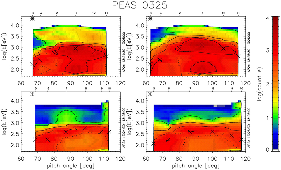
Figure 8. The electron energy and pitch angle distribution obtained with the PEAS AP–2 sensor during electron beam emission (orbit 325, G2 injector with magnetic deflection, F40K mode) accompanied by xenon plasma injection (F0 mode) on the left and neutral xenon (Xe-B) on the right. (Top) AP–2 sectors seeing the electrons from inside the beam flux tube (group 1), (Bottom) Sectors seeing the electrons from outside (group 2). The UEM injection pitch angle denoted by × +. (Reprinted from Nemecek et al., 1997, copyright 1997 by the American Geophysical Union).
No significant ion fluxes were registered by the PEAS sensors during the UEM and UPM active injections (in different mode combinations), the counts usually remained near the noise level (Nemecek et al., 1997). Only sporadically an ion group with energy corresponding to the UPM acceleration voltage was registered in a narrow spatial angle—usually just one sector. Although the PEAS sensors had no mass resolution capability it was assumed these were ions from the plasma cloud edge that after one gyro-revolution returned to the PEAS input aperture.
More recently, Budko et al. (2003) also analyzed the PEAS electron and ion distribution behavior during the electron beam injections related to the HF wave emissions (see section 3.3.3). They emphasized detection of very short-term bursts of accelerated ions with energies up to several hundreds of electronvolts immediately after switching on the electron gun. The effect again corresponds to generation of strong electric fields in the near zone.
3.3.2. Plasma Environment in the IK–25 Spacecraft Vicinity, Diamagnetic Cavity
The UPM plasma cloud density evolution in the APEX active experiments were estimated by Volokitin et al. (2000). The kinetic energy 200eV of accelerated xenon ions corresponds to ~17 km/s speed. For the typical UPM emission parameters 2.5 × 10¹⁹ ions/s (~3mg/s) assuming density decreased as ~1/R2 the xenon plasma expanded to the ambient plasma density levels ~1010m−3 at distances R≃ 300–400 m. From similar estimations the xenon plasma dynamic pressure exceeded the geomagnetic field pressure for . For the APEX orbit (B ~ 3–5 × 10⁴nT) the plasma cloud could expel the geomagnetic field and create a diamagnetic cavity to distances 5–10 m from the spacecraft (the xenon ion gyroradius 1–2 km) due to electrical polarization of plasma cloud. While the injected energetic xenon ions move more-or-less freely across the magnetic field, the electrons are magnetized and follow the magnetic field lines. The electrons partly drift due to the polarization electric field across the magnetic field and at the same time they drag the magnetic field lines in their effort to follow the cloud ions. However, this process could be noticeably depressed if the ambient plasma electron density is sufficient to support the parallel electric current neutralizing the polarization electric field. Volokitin et al. (2000) studied the diamagnetic cavity formation during the IK–25 xenon plasma injection using two magnetometers (see Figure 9). The SGR–5 magnetometer mounted on a boom at least 7–12 m from the xenon plasma beam registered magnetic field fluctuations with amplitude ~10nT while the service magnetometer mounted very near the injected cloud observed magnetic depressions 1,500–2,000 nT. The experimental data documented the active extrusion of the geomagnetic field in the initial phase of the plasma cloud expansion. The authors compared the observational results with a theoretical model based on ideas from analysis of previous experiments PORCUPINE (Hausler et al., 1986; Oraevsky et al., 2003) and AMPTE (Mishin et al., 1988).
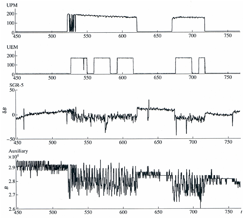
Figure 9. Illustration of the diamagnetic cavity formation as seen in the time-dependent variations of the magnetic field. Horizontal axis—the time [s] lapsed from 04:37:02 UT, obtained during the xenon plasma injection on March 13, 1992 (orbit 1019). From top to bottom the UPM and UEM acceleration voltage [a.u.], deviation of the magnetic field strength [nT] from a mean level (SGR–5), and the service magnetometer total magnetic field [nT]. (Reprinted from Volokitin et al., 2000).
3.3.3. Beam-Plasma Interaction, ELF/VLF, and HF Waves Generation
Near-zone VLF wave observations (NVK-ONCH instrument) during the APEX xenon plasma injection have been studied by Mikhailov et al. (1998, 2000). While the unmodulated xenon plasma emission was accompanied by a broadband VLF noise, during the 1 kHz and 125 Hz beam current modulation (F1000 and F125 modulation modes), the basic frequency and its harmonics were registered in the magnetic field data. Simultaneous disturbances in electron temperature and plasma density from the KM–10 device were detected. While the onset of fast magnetic field variations coincided with the plasma injection switch-on, they lasted much longer after the injection off, with time-varying spectral amplitude profiles across the ELF/VLF range. The authors attributed the observed delays to a joint movement of the satellite and a packet of waves created inside the plasma cloud (assuming different wave modes were excited during the injections and some of them were able to travel in the direction of the satellite velocity according to the authors). Similar results were obtained also in previous higher flow, ram directed, xenon neutral gas releases from the ACTIVE Interkosmos–24 satellite (Klos et al., 1998).
Kiraga et al. (1995, 1998) analyzed HF emissions during modulated electron beam injections (F40K mode, 2μs pulses, neutral xenon simultaneous release) in the middle latitude dayside ionosphere (altitude ~700−1, 100 km) and near the nightside perigee (altitude ~415−470 km, middle and high latitudes). In the regime of strong beam-plasma interaction, the HF dipole antenna was effectively screened from the HF broadcasting stations radiation as probably a large volume of excited plasma around the emitting satellite scattered these waves. Complex structures of peaks near harmonics of local plasma, cyclotron, and upper-hybrid frequencies were present in the HF wave spectra of PRS–3 during the electron injections, varying with ionospheric parameters and evolving injection configuration along the orbit. Dublet of local plasma and upper hybrid frequency peaks was the most prominent emission during the former interval and harmonics of this structure were also excited. During the latter injection the recorded spectra were more diverse, main emissions consisting of even harmonics of the cyclotron frequency fc, dublets below 2fc, or selectively excited emissions near 3fc and 4fc. The authors interpreted the individual spectral peaks as emissions characteristic for synchrotron maser radiation created in a system of cold magnetoplasma and cold, weakly relativistic, very diluted electron beam.
Considering the electron beam under the F40K modulation as “strong,” Kiraga (2003) brought a picture of HF emissions obtained during “weak” electron beam emissions in the S250 and S15.6 modulation modes. Evolution of spectra during the beam cycle, presence of modulation frequency harmonics and structures around the upper hybrid frequency are discussed as well as effects of antenna charging and electron current coupling between plasma and antenna. The electron beam injection as a tool for continuous monitoring of ambient plasma density by reception of emissions generated in ambient (fp, fuh) frequency band is also discussed in the paper.
Budko et al. (2003) investigated HF waves excited by the pulsed electron injections and xenon plasma releases in the near zone. In lower altitude, subauroral dayside ionosphere they recorded emissions at the local plasma frequency fp, 2fp, and 4fc during a weak electron injection alone. Later on during the simultaneous electron beam (S250) and xenon plasma (F0) injections, whistler mode wave excited at the electron beam modulation frequency ~250kHz and resonances at the first three cyclotron frequency harmonics were present in the PRS–3 frequency range (the local plasma frequency during the xenon plasma release was estimated by the authors to ~16MHz which made detection of plasma resonance of an electron beam and background plasma impossible). During strong electron injection modulated by the 250kHz frequency, with only neutral xenon release, the dublet of local plasma and upper hybrid frequency peaks (reported by Kiraga et al., 1995 for 40kHz modulation) was clearly present together with whistler mode waves possibly up to the 6th to 8th harmonic of the electron beam modulation frequency. During nightside subauroral and middle latitude electron beam injection (F40K), resonant peaks near even electron cyclotron frequency harmonics (2fc, 4fc, 6fc, 8fc) or combinations with the plasma frequency (fp, 2fc+fp, 4fc+fp, 6fc+fp) were recorded in the former case, plasma resonance harmonics only in the latter case.
Recently, very detail analyses of the beam-plasma instability development, excitation of VLF/LF and HF waves, coupling of waves, particle heating and acceleration related to different APEX experiment configurations (injections through/opposite the xenon plasma cloud, quasi-perpendicular electron beam injections, injections of differently modulated electron beam - S250, F40K modes) have been performed in a series of papers by Baranets et al. (2007, 2012, 2017) where the authors compared theoretically derived quantities with data obtained onboard IK–25 (VLF/HF emissions, electric and magnetic field fluctuations, plasma parameters) and remotely by MAGION–3 (HF emissions, accelerated electron fluxes, thermal plasma parameters). Presented results reflect the development of a beam or beam-anisotropic instabilities in the ionospheric plasma, some of them being a consequence of more complex combination (nonlinear) mechanisms of interaction, developing during injection of a beam into a beam.
Baranets et al. (1999, 2000), and Oraevsky et al. (2001) analyzed waves generated during the DC and modulated electron beam injections in the near zone in a special dayside configuration when the electron beam was injected downward () and, asynchronously to the UEM cycle (S250 modulation mode), the neutral xenon/xenon plasma (F0 mode) were released upward (), see also Figure 3. Beam-plasma discharge did not occur during this quasi-transverse injection, conditions for the beam-plasma instability development/suppression were investigated in these papers. Theoretical and numerical analysis of the observed data led the authors to the following conclusions:
• The beam plasma instability due to the electron beam injection () excited ELF/VLF waves activity below the ion cyclotron frequency, growth of the magnetic component of VLF waves was observed. Increase of thermal spread of the beam electrons leads to the suppression (decay) of the excited VLF waves.
• Magnetic disturbances were recorded, caused by either the beam primary electrons or return currents associated with the beam-plasma instability.
• The electron beam injection was accompanied by strongly anisotropic plasma heating and modulation of the plasma (ion) flows in the vicinity of the satellite.
• For an unmodulated electron injection, the efficiency of plasma (beam) heating with respect to the transverse component decreases substantially when αpe + Δα′/2 > 90° (Δα′ is the electron beam effective pitch-angle width).
• The thermal flux of O+ and NO+/ ions decreased during the DC electron injections, probably as a consequence of the resonant coupling with the excited VLF waves.
• During the modulated beam-plasma interaction, the plasma resonance heating of Tex, Tey components at the modulation frequencies corresponding to the O+ and NO+/ ion plasma frequencies were recorded.
Baranets et al. (2007, 2012, 2014) studied modulated electron injections (S250 mode) performed in the same direction (upward, ) as the xenon plasma release. Experimental observations of the anomalous fluxes of fast charged particles, disturbances of quasi-steady and ELF/VLF magnetic field components, and thermal plasma ion fluxes have been considered using the IK–25 and MAGION–3 data obtained from two consecutive orbits with similar ionospheric plasma and injection parameters. Anomalously large disturbances 400–500 nT and fluxes of fast electrons were registered by MAGION–3 (~100 km from IK–25) during these injections. In their analysis the authors did not consider the xenon plasma cloud as a diamagnetic cavity in the nearest vicinity of the spacecraft, describing it as a hollow beam of about half a kilometer diameter. The electron beam current profile was considered as a hollow flow after several gyro-turns due to electrostatic repulsion, electron beam modulation was commented in the papers. In such experimental configuration (Figure 10A) the system of the electron beam nested in the xenon ion beam was axially asymmetric with respect to the magnetic field direction due to the small velocity of xenon ions (), which was comparable to the velocity of the satellite (viz/vs~1.5) moving at an angle to the magnetic field. The beam of heavy xenon ions injected at the pitch angles range up to with a maximum flux density within the angles would play the role of a damping layer for waves induced by the electron beam in the entire interaction region in the vicinity of the satellite. Main attention was paid to study the electromagnetic and longitudinal waves excitation in different frequency ranges and the energetic electron fluxes disturbed due to wave-particle interaction with whistler waves. The authors described dispersion relations for the whistler-mode wave excitations for the beam-driven electromagnetic instability and estimated its growth rate (in a weak beam approach).
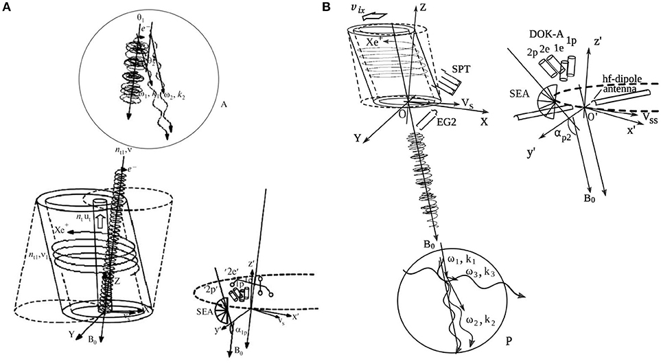
Figure 10. (A) Electron beam injection (e−, modulation mode S250) directed through the hollow beam of xenon ions (Xe+, no modulation F0) with the beams density and velocity nbe, v, and nbi, vi, respectively. Release of the electron flow with the density and stream velocity ne, ue, for a compensation of the ion beam charge at the output of UPM is shown by the up arrow. Here, B0 and vs are the directions of the quasi-steady magnetic field and the satellite velocity in the XYZ coordinate system, Z-axis points away from the Earth. Circle A—region of whistler-mode wave (ω, k) generation by the electron beam e− at angle θ to the magnetic field. (“1e, 1,” “2e, 2p”) are two pairs of the DOK–A–S energetic particle sensors, SEA is the six-sector soft electron detector of the MPS/PPS spectrometer, α1p is the pitch-angle of the first sector registration in the x', y', z' MAGION–3 coordinate system. Injection configuration for orbits 201, 202. (Reprinted from Baranets et al., 2014). (B) Electron beam injection (e−, modulation mode F40K) directed opposite to the hollow beam of xenon ions (Xe+), disposition sketch of the electron gun (EG2) and stationary plasma truster (SPT) are shown in the IK–25 satellite coordinate system OXYZ. Sensors for the soft and fast charged particles belonging to the spectrometers MPS/PPS (SEA) and DOK–A–S (“1e, 1p,” “2e, 2p”), respectively, and hf-dipole antenna (HF-receiver PRS–S) are shown in the subsatellite system Ox'y'z', where αp2 is a pitch-angle of soft electrons detected through the 2nd sector of the SEA sensor aperture; vix as well as Vs and Vss are the inertia Xe-ion velocity shear and velocities of the satellite and subsatellite, respectively. Region P is a symbolic sketch of three-wave interaction. The distance OO' was about ≃110 km for orbit 190. (Reprinted from Baranets et al., 2017, with permission from Elsevier).
Recent papers (Baranets et al., 2012, 2017), analysing the stationary electron beam injection (F40K modulation mode, 2μs pulses) with simultaneous xenon neutral gas/plasma release (Figure 10B), reported a number of beam-plasma interaction effects both in the vicinity of the injecting satellite and in the far zone (subsatellite observations at distance about hundred kilometers, see also section 3.4.2). Based on thermal plasma ion fluxes, photometric, and wave data they found their correlation with beats of the density and velocity waves in the beam core in the high-frequency parallel and perpendicular wave fields. Theory and numeric estimations of correlation amplitudes are included. Onboard IK–25, sudden VLF amplification lasting ~7–8 s was recorded. Analysis shows the burst was observed near the linear stability boundary for the slow beam mode excited due to a dissipation of beam kinetic energy. HF waves recorded by MAGION–3 were disturbed during the electron beam/xenon injections. The amplification of the HF wave amplitude in the range ~0.6−1.1MHz (ωce, ωpe, k0u) and 2.0−2.3MHz (~2k0u) were correlated with the VLF burst at IK–25. Narrow bursts within the 2.20−2.3MHz range were modulated by the VLF-LF wave activity in accord with the xenon ion beam current Ibi. Stimulated soft electron fluxes also recorded by MAGION–3 were explained as disturbed due to the Cherenkov wave-particle interaction (acceleration/scattering)—50−70eV electrons interacted with excited waves near 0.1 MHz, fluxes with energies > 0.5keV could be stimulated by the beam-induced waves around k0u near the linear stability boundary for longitudinal waves.
3.4. Distant Injection Effects
3.4.1. Energetic Particles
Nemecek et al. (1996) and Prech et al. (2002) reported on observations of short intensive bursts of narrow-beam electrons onboard MAGION–3 during the electron injections from the main IK–25 satellite. The events were registered in the middle geomagnetic latitudes (INL < 55°) near local noon when the two satellites moved approximately along the same magnetic meridian at relative distances 64–550 km. The localization of the burst observation to the altitudes from 800 to 1,500 km was probably a consequence of the local time favorable for the observation, the satellite orbit, and other parameters. The pitch angle distributions were narrow (< 10°) and the electrons precipitated toward the atmosphere. The events lasted 4–10 s in the narrow MPS low-energy channel, but some events were doubled or tripled. The burst cross section was spatially limited to several tens of kilometers in the direction of the orbit and the electron energy extended to several hundred keV, without measurable dispersion indicating proximity of the source. The events had different characteristics than electron microbursts already reported in the literature (for a short review see Prech et al., 2002). Examples of bursts registered by MAGION–3 are presented in Figure 11.
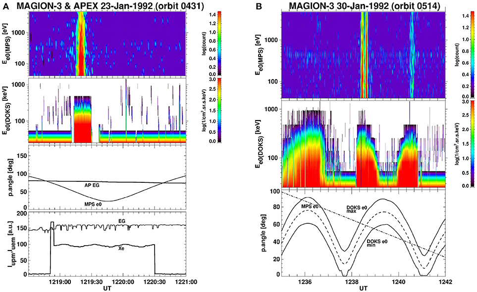
Figure 11. Examples of single and multiple electron bursts registered onboard MAGION–3. (A) From top to bottom: MPS e0 channel dynamic spectrogram (to 5 keV, parallel to the satellite axis); DOK–S e0 channel spectrogram up to 1 MeV; IK–25 UEM electron beam pitch angle (AP EG) and the pitch angle of MPS e0 electrons; monitors of the IK–25 UEM and UPM injectors. (B) From top to bottom: MPS e0 and DOK–S e0 channel spectrograms; pitch angle of electrons registered by MPS e0 (dashed line), the range of pitch angles covered by the DOK–S e0 channel (two thin min/max lines), and the approximate change of the electron burst pitch angle with time (dash-dotted line). (Originally published in Prech et al., 2002, distributed under the Creative Commons Attribution 3.0 License).
The main IK–25 satellite did not detect electron bursts of this kind as no other satellite orbiting in this region did but active electron injections from IK–25 were performed when the bursts were detected. The events of this kind were detected only during the UEM F40K mode operation and not during the S250 or other modulation mode injections. Neutral xenon or xenon plasma (UPM F0/F1000 modes) were simultaneously released so the quality of the satellite charge neutralization seems not to be important. Thirty four F40K-mode electron injections were scheduled on IK–25 during January and February 1992, but not all were 100% successful and with the MAGION–3 data coverage. The burst observation probability per session was about 0.25.
The energy-pitch angle properties of the bursts indicate according to Prech et al. (2002), that the bursts were created from low-temperature plasma or the beam emitted from the IK–25 satellite by some acceleration process effective only in one direction with respect to the magnetic field (e.g., field-aligned potential drop), the spread of the pitch angles being caused by the original thermal velocity distribution. The authors were not in favor of the other possible source—ring current electrons released by some mechanism induced by particles emitted from IK–25. Questions if the beam-plasma interaction is able to accelerate the electrons to the observed energies, how the observed electrons moved across the magnetic field lines, and why the electron bursts were observed only in part of the active experiments are further discussed in the paper.
Baranets et al. (2012, 2014) reported on similar kind of fast electron fluxes (MAGION–3/DOK–S). The bursts had highly fluctuating wide (scattered) pitch-angle distribution, the electrons were simultaneously detected by both the DOK–S electron channels. The bursts were observed during the UEM S250 electron injection mode different from the previous paragraph case. According to the authors electromagnetic waves were excited via the electron-cyclotron resonance with the beam and subsequently scattered in a wave-particle interaction (Cherenkov resonance) giving rise to the energetic electrons distantly observed by MAGION–3.
3.4.2. HF Waves
Rothkaehl et al. (1995) reported simultaneous observations of RF emissions on the mother IK–25 satellite and the MAGION–3 subsatellite during a downward UEM modulated electron beam injection (F40K mode, 2 μs pulses, only neutral xenon released by UPM during this case). The spacecraft separation was about 200 km. Strong electrostatic emissions at the upper-hybrid plasma frequency and its harmonics at the main spacecraft and spikes in the HF frequency range on MAGION–3 (see Figure 12) were simultaneously detected. The first emission peak was at frequency 2.15MHz and three harmonics were also recorded. The authors concluded the electromagnetic emission of the oscillating current created by the injected electron beam was observed, the base frequency attributed to the electron beam current properties and the half-width of the emission line ~50kHz referred to the electron gun pulse repetition frequency.
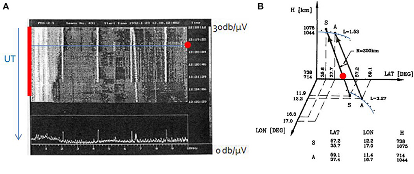
Figure 12. HF waves registered onboard MAGION–3 durin the electron beam emission from IK–25. (A) Shows a sequence of radio spectra (PRS-2-S, vertical axis for time) along the orbit 0431. Emission intensity from black 0 dB/μV to white 30 dB/μV with nine equidistant levels. During the IK–25 electron beam injection (marked with the red bar) spiky emissions at ~2.1MHz and harmonics were registered. Bottom plot represents a single spectrum (12:19:37 UT, blue line cut). (B) Displays the relative position of the IK–25 satellite (A) and MAGION–3 (S) in the geographic coordinates. Their relative distance during injection was about 200 km. The dotted lines present the geomagnetic field lines. The injection started at 12:18 UT (altitude 714 km) and finished at 12:24:30 UT (alt. 1,044 km). The red dots (both panels) mark the electron burst reported by Prech et al. (2002) in MAGION–3 data. (Reprinted from Rothkaehl et al., 1995, with permission from Elsevier).
3.4.3. Ground VLF Transmitter Spectral Broadening
Spectral broadening of signals from ground-based VLF transmitters (16.5, 12.6, 11.333 kHz carriers) was observed onboard MAGION–3 during the modulated electron beam injection from the main IK–25 satellite (Oraevsky et al., 1994). The broadening of order of 300–500 Hz was apparently correlated with the 2-s cycle of the UEM gun pulses modulated in the range 30.5–31,250 Hz (2 μs length) while no effects were observed for modulation frequencies 62.5, 125, and 250 kHz (Figure 13). The observations were made in the middle latitude ionosphere at altitudes 1,175–1,580 km, the distance between the two satellites was about 250 km. Scattering of whistler-mode waves into quasi-electrostatic waves by periodic small-scale plasma inhomogeneities or ELF plasma turbulence created by the pulse-modulated electron beam were discussed as possible causes of the observed phenomenon. The authors compared the observation with previous rocket and space shuttle experiments and discussed both local (near the injection source) and remote (e.g., ionizing effect of the electron beam at the ionospheric E-region heights) mechanisms of plasma irregularities creation that had been suggested in literature.
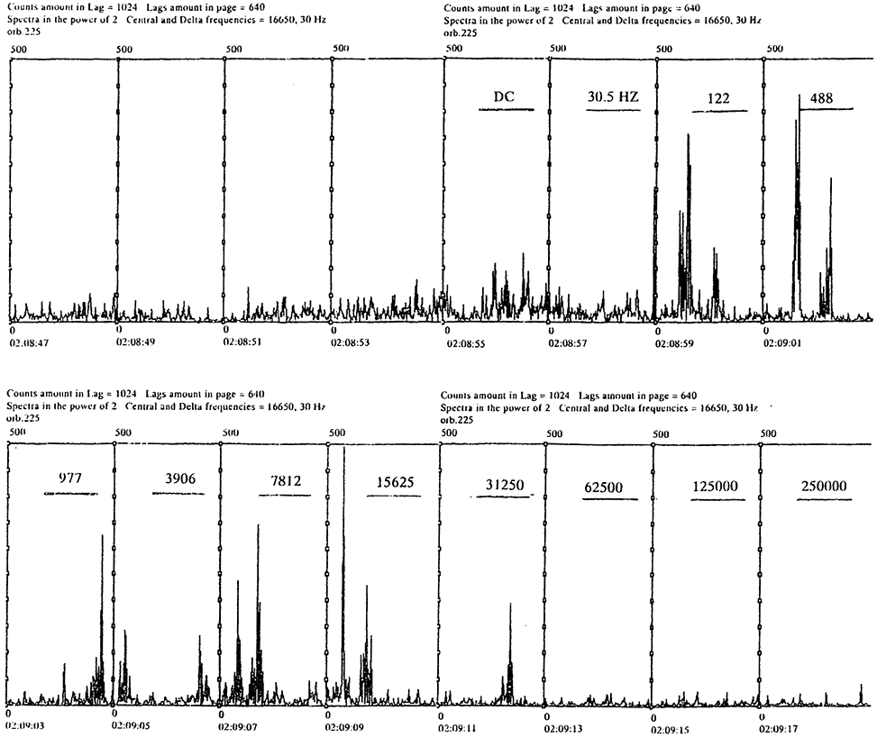
Figure 13. Wave intensity registered by MAGION–3 at the frequency 16,650 Hz, i.e., 150 Hz away from the VLF transmitter carrier. The electron beam pulses are shown as horizontal bars with the modulation frequency indicated. (Reprinted from Oraevsky et al., 1994, with permission from Elsevier).
3.5. Ionospheric Heating Experiments
Magnetosynchronous active experiments belong to a different group of active experiments in space plasma. One of possible approaches to investigate evolution of physical phenomena along a geomagnetic flux tube after a disturbance injection could be to use a special satellite orbit which runs in parallel with the geomagnetic field line for a sufficient time. These orbits are called magnetosynchronous and a concept of such active experiment in frame of the APEX programme was introduced by Ruzhin and Vaskov (1992). For the APEX orbit with inclination ~80° the magnetic meridian fell in the orbital plane about twice per day. The experiment was realized using the Dushanbe ionospheric heater for several IK–25 flyover orbits both near perigee and apogee.
Oraevsky et al. (1998b) reported on observation of the plasma barrier transparency effect (passing of a shortwave signal below the f0F2 frequency across the F2 layer, in the particular case for the heater frequency 5.98MHz the barrier thickness was estimated ~100 km). The ballistic transport mechanism was suggested by the authors to explain detection of increased noise at frequencies around 6 MHz from PRS–3 data while the IK–25 satellite was magnetically connected to the heated part of the ionosphere. Oraevsky et al. (1998a) reported on similar results for the APEX and CORONAS satellites and the SURA ionospheric heating facility, more recently the experiment was repeated with the DEMETER satellite and the SURA heater (Zhang et al., 2016).
Variations of electron temperature and density near IK–25 apogee observed when magnetically connected to an ionospheric spot heated by the Dushanbe facility were reported and analyzed by Oraevsky et al. (1998b). Propagation of disturbances from locally artificially heated ionosphere into magnetosphere was modeled e.g., by Ruzhin and Vaskov (1992) and recently by Borisov et al. (2015).
4. Comparison With Other Experiments and General Discussion
The analysis of the KM–10 floating probe potential and PEAS charge particle spectra has shown small charging and good neutralization during electron beam emissions from the IK–25 satellite. A larger spacecraft surface and methods of electron beam charge compensation made a difference comparing the electron beam emissions in a similar range of altitudes from the G–60–S sounding rocket (Managadze et al., 1988) or even at lower altitudes (SCEX–3, Mullen et al., 1991) where high body charging was observed.
Measurements of angular-energetic spectra of charged particles were rare prior to the APEX project. Previous sounding rockets and spacecraft active experiments included simple electrostatic analyzers that did not allow detail studies of pitch-angle distributions of charged particles in the vicinity of the beam emitting body. The space shuttle Spacelab–1/SEPAC and TSS–1/SETS active experiments (e.g., Burch, 1986; Watermann et al., 1988; Oberhardt et al., 1993) provided electron angular distributions with high time resolution but related pitch-angle distributions were not discussed. Moreover, configurations of these experiments were different from APEX. Most of the shuttle surface was covered by non-conducting ceramic tiles. The electron spectrometers were mounted on a platform inside the shuttle payload bay where at least half of space was shielded. The angular distribution of the return current electrons during electron beam emissions did not show flux decrease in the shielded sectors indicating the origin of electrons near the platform. Their angular distribution depended more on the sector view angles against the platform normal and the direction toward the electron gun. For pitch-angles close to zero the electron energy was limited to about primary beam energy while for pitch-angles reaching ~80° intense electron flux was observed up to the spectrometer upper range (≈2.5 times the beam energy). In the APEX experiments, return electrons with energies of the primary beam and above were not observed in the IK–25 vicinity.
We consider important our observations of the short high-energy electron bursts in the remote zone by MAGION–3 during the electron injections. To our knowledge these observations have not been confirmed by other experiments yet, actually because no other experiment with two-point observations similar to APEX has been performed up today. Comprehensive wave and particle measurements were realized during the electron beam emissions from the STS–3 and Spacelab–2 space shuttle platforms (e.g., Gurnett et al., 1986; Banks et al., 1987; Bush et al., 1987) using the independent Plasma Diagnostic Package (PDP; mounted on a manipulator arm or free-flying, resp.) but they were made in the near zone at distance ~101−102m. The MAGION–3 HF wave measurements also remain unconfirmed for the same reasons.
Kawashima and Akai (1986) reported on waves registered onboard the satellite JIKIKEN (EXOS-B) on an elongated orbit with apogee ~25, 000 km that were excited during electron beam injections (much weaker than later used in the space shuttle or APEX experiments). They also observed waves near upper-hybrid or plasma frequencies, electron-cyclotron frequency, and LF frequencies related to the electron beam instrumental modulation. Accompanying harmonics were supposed to be generated instrumentally due to the saturation of the signal level. Harmonics of the plasma frequency in the APEX data might have the same instrumental origin which was not discussed by Budko et al. (2003), or they could truly exist due to the beam bunching as noted by Kiraga et al. (1998).
From their analysis of the return electron spectra, Nemecek et al. (1997) and Budko et al. (2003) deduced a presence of electric fields of a strength up to 100V/m in the vicinity of the spacecraft that was sometimes questioned by a part of the scientific community and would require further study. Anyway, according to the 3D computer simulation by Pritchett (1991) electric fields of the order of tens of volts per meter can be expected during an electron beam injection in similar conditions.
Complexity of the IK–25 design (structure, surfaces, etc.) and a lack of related engineering data have not allowed to synthesize a more realistic model of the electron beam and xenon plasma injections and return currents in the near zone including the satellite influence that would help to interpret the observational data. Earlier papers related to the APEX wave observations (Kiraga et al., 1998; Budko et al., 2003; Kiraga, 2003) did not aim to establish a comprehensive theory of wave generation by the APEX electron beam and xenon plasma injections but in their analysis of observed data they rather referred to previous theoretical treatments of beam-plasma interaction which is non-linear in the APEX case. Full understanding of the coexistence and competition between various instabilities requires dedicated simulations which would take into account many unique characteristics of the APEX experimental setup, but such APEX-related simulation models have not been developed. Baranets et al. (2007, 2012, 2017) presented non-linear theoretical analysis of beam-plasma interaction for systems of electron beam nested in or opposite to the ion beam that were related to the APEX injection configurations. Fast electrons from the MAGION–3 observations were explained as a result wave-particle interaction: whistler waves excitation by the electron-cyclotron resonance and subsequent scattering. To verify their results, a detail knowledge on wave propagation (k vector) would be useful, but such data were not gathered in the APEX project.
The APEX project suffered from a relatively short life-time of active devices UEM–2 and UPM. The active experiments with charge particle beam injections were performed only during the first six months after the launch, recurrent technical issues precluded to obtain complementary data during the second half year or to repeat unsuccessful active experiment configurations. Above that, some operational and science information was not available (fast beam current monitoring, optical diagnostics, cold plasma spectra), the field and wave instruments did not provide complete information. Technical difficulties connected with the precise control of the MAGION–3 orbit did not allow intended near- and mid-zone observations during the active experiments while the hundred-kilometers satellite distances were preferred for two-point passive measurements in the auroral region. Last but not least, the available computer network communication means limited daily supervision by scientists, quick preliminary data analysis, and feedback toward the main satellite operation control—reasonable demands of a contemporary active experiment.
Many questions connected to the APEX active injections have not been answered, e.g., what was the size and structure of the electron acceleration region or what conditions allowed the observed acceleration up to relativistic energies. A new mission could provide multi-point measurements in medium and distant zones of injection (1−103 km) using a constellation of nanosatellite probes that would allow the study of waves growth and propagation and electron acceleration simultaneously at different distances along and perpendicular to the beam. If feasible, the orbit (active experiment parts) should be chosen so as the emission pitch-angle, altitude, latitude, L shell, and local time are not closely bounded, with sufficient coverage of parameter space and repeatability of emission parameter subsets. Wave-particle correlators and ion analyzer with mass selection would be a useful extension of the APEX scientific payload. A new experiment should be also equipped with a 3D measurement of LF and HF electric and magnetic fields. Such data, when processed using the latest analysis methods to obtain wave propagation direction (e.g., Santolik et al., 2003), polarization (Santolik et al., 2016; Taubenschuss and Santolik, 2018), and HF mode identification (Santolik and Parrot, 2006), can give a new insight into the beam-plasma interaction processes. Last but not least, Kiraga (2003) discussed also usage of the APEX type electron injection and HF waves analysis for monitoring density of cold plasma.
5. Conclusions
The broadly focused APEX active experiments have an important place in the long line of active space experiments. They brought new results or they complemented results of previous projects made using sounding rockets, space shuttles, or scientific/technological satellites in ionosphere and magnetosphere. The main achievements of the active experiments within the APEX project could be listed as
• successful neutralization of the spacecraft charge during electron beam emissions by xenon/xenon plasma releases at altitudes 500−1, 000 km,
• analysis of ELF/VLF and HF wave activity near the electron-beam emitting satellite,
• first in-situ measurements in the distant zone of injection (MAGION–3 subsatellite),
• MAGION–3 observation of electron bursts accelerated to energies of several hundred keV during the electron beam injections from the main satellite.
The mother—daughter (multi-point) satellite projects were quite rare till the end of the twentieth century and we can treat the APEX project also as the pathfinder in this methodology and the MAGION series satellites as predecessors of contemporary micro, nano, and cube satellites. Repeating the APEX project with state-of-the-art scientific equipment and a fleet of small satellite probes around would certainly bring new scientific achievements and help to answer some still open questions in the field of space plasma.
Author Contributions
YR, VD, ZN, and JS contributed to the conception and design of the APEX project. LP wrote the first draft of the manuscript. YR wrote substantial parts of several sections of the manuscript. LP, JS and ZN selected and prepared figures to be reprinted in this review. All authors contributed to the manuscript revision, read, and approved the submitted version.
Funding
The work of LP, ZN, and JS was supported by the Czech Science Foundation contract 17–06065S.
Conflict of Interest Statement
The authors declare that the research was conducted in the absence of any commercial or financial relationships that could be construed as a potential conflict of interest.
Acknowledgments
We thank to Jiri Simunek for providing the MAGION–3 to IK–25 orbital delay data.
References
Afonin, V. V., Grechnev, K. V., Ershova, V. A., Roste, O. Z., Smirnova, N. F., Smilauer, J., et al. (1994). Ion composition and temperature of ionosphere at maximum of the 22nd solar activity cycle from satellite Interkosmos–24 (ACTIVE project). Kosm. Issled. 32, 82–94. in Russian.
Artsimovich, L. A., Andronov, I. M., Yesipchuk, Y. V., and Barsukov, I. A. (1974). Development of a steady plasma engine (SPE) and its testing onboard the “Meteor” artificial satellite. Kosm. Issled. 12, 451–468. in Russian.
Banks, P. M., Raitt, W. J., White, A. B., Bush, R. I., and Williamson, P. R. (1987). Results from the vehical charging and potential experiment on STS–3. J. Spacecr. Rockets 24, 138–149. doi: 10.2514/3.25887
Baranets, N., Ruzhin, Y., Dokukin, V., Ciobanu, M., Rothkaehl, H., Kiraga, A., et al. (2017). Injection of 40 kHz-modulated electron beam from the satellite: I. beam-plasma interaction near the linear stability boundary. Adv. Space Res. 59, 2951–2968. doi: 10.1016/j.asr.2017.03.030
Baranets, N., Ruzhin, Y., Erokhin, N., Afonin, V., Vojta, J., Smilauer, J., et al. (2012). Acceleration of energetic particles by whisler waves in active space experiment with charged particle beams injection. Adv. Space Res. 49, 859–871. doi: 10.1016/j.asr.2011.12.001
Baranets, N., Ruzhin, Y., Erokhin, N., Afonin, V., Vojta, J., Smilauer, J., et al. (2014). Resonance effects of wave-particle interactions during artificial charged particle beam injections in an ionospheric plasma. Kosm. Nauka Technol. 20, 3–26. in Russian. doi: 10.15407/knit2014.05.003
Baranets, N. V., Ruzhin, Y. Y., Afonin, V. V., Oraevsky, V. N., Pulinets, S. A., Dokukin, V. S., et al. (1999). Active experiment in space for investigation of beam plasma interactions. Results of the APEX project. Adv. Space Res. 24, 981–984. doi: 10.1016/S0273-1177(99)00561-X
Baranets, N. V., Ruzhin, Y. Y., Afonin, V. V., Oraevsky, V. N., Pulinets, S. A., Dokukin, V. S., et al. (2000). Electron beam injection quasilateral to the geomagnetic field from the data of Intercosmos–25 satellite: APEX project. Kosm. Nauka Technol. 6, 49–62. in Russian. doi: 10.15407/knit2000.05.049
Baranets, N. V., Sobolev, Y. P., Ciobanu, M., Vojta, J., Smilauer, J., Klos, Z., et al. (2007). Development of beam-plasma instability during the injection a low-energy electron beam into ionospheric plasma. Plasma Phys. Rep. 33, 995–1013. translated from Russian. doi: 10.1134/S1063780X07120057
Borisov, N., Ryabova, N., and Ruzhin, Y. (2015). Dynamics of plasma density perturbations in the upper ionosphere and the magnetosphere under the action of powerfull HF radio waves. J. Atmos. Solar Terr. Phys. 134, 102–108. doi: 10.1016/j.jastp.2015.09.018
Budko, N. I., Prutenskii, I. S., Pulinets, S. A., Dokukin, V. S., Shutte, N. M., Plokhova, O. A., et al. (2003). Some features of the plasma turbulence region in the active experiments onboard the APEX satellite. Geomagnet. Aeron. 43, 335–344. translated from Russian.
Burch, J. L. (1986). Space plasma physics results from Spacelab–1. J. Spacecr. Rockets 23, 351–335. doi: 10.2514/3.25115
Bush, R. I., Reeves, G. D., Banks, P. M., Neubert, T., Williamson, P. R., Raitt, W. J., et al. (1987). Electromagnetic-fields from pulsed electron-beam experiments in space — Spacelab–2 results. Geophys. Res. Lett. 14, 1015–1018. doi: 10.1029/GL014i010p01015
Cambou, F., Dokukin, V. S., Ivchenko, V. N., Managadze, G. G., Migulin, V. V., Nazarenko, O. K., et al. (1975). The Zarnitsa Rocket Experiment on Electron Injection. Space Research XV. Berlin: Akademie-Verlag.
Cambou, F., Dokukin, V. S., Lavergnat, J., Pellat, R., Reme, H., Saintmarc, A., et al. (1980). General description of the ARAKS experiments. Ann. Geophys. 36, 271–283.
Choueiri, E. Y., Oraevsky, V. N., Dokukin, V. S., Volokitin, A. S., Pulinets, S. A., Ruzhin, Y. Y., et al. (2001). Observations and modeling of neutral gas releases from the APEX satellite. J. Geophys. Res. 106, 25673–25681. doi: 10.1029/2001JA000040
Dokukin, V. S. (1992). “The APEX project scientific facility orbital complex,” in APEX Project. Scientific Purposes, Simulation, Technique and Equipment of Experiment, eds V. N. Oraevsky and Y. Y. Ruzhin (Moscow: Nauka), 16–29. in Russian.
Dokukin, V. S., Mishin, E. V., Markeev, A. K., Milinevsky, G. P., Mishin, E. V., Moisya, R. I., et al. (1981). Results of Zarnitsa–2, a rocket experiment on artificial electron beam injection in ionosphere. Adv. Space Res. 1, 5–15. doi: 10.1016/0273-1177(81)90268-4
Grandal, B. (ed.). (1982). Artificial Particle Beams in Space Plasma Studies. NATO Adv. Study Inst. Ser. B: Physics. New York, NY: Plenum Press.
Gurnett, D. A., Kurth, W. S., Steinberg, J. T., Banks, P. M., Bush, R. I., and Raitt, W. J. (1986). Whistler-mode radiation from the Spacelab–2 electron beam. Geophys. Res. Let. 13, 225–228. doi: 10.1029/GL013i003p00225
Haerendel, G., and Sagdeev, R. Z. (1981). Artificial plasma jet in ionosphere. Adv. Space Res. 1, 29–46. doi: 10.1016/0273-1177(81)90270-2
Hausler, B., Treumann, R. A., Bauer, O. H., Haerendel, G., Bush, R., Carlson, C. W., et al. (1986). Observations of the artifically injected porcupine xenon ion beam in the ionosphere. J. Geophys. Res. 91, 287–303. doi: 10.1029/JA091iA01p00287
Hess, S., Inguimbert, V., Siguier, J., Payan, D., Gerhard, A., DAccolti, G., et al. (2016). “Plasma current collection of high voltage solar array: numerical investigation,” in 14th Spacecraft Charging Technology Conference SCTC 2016, ESA/ESTEC (Noordwijk). Available online at: https://hal.archives-ouvertes.fr/hal-01371932/document
Izhovkina, N. I., Prutensky, I. S., Pulinets, S. A., Erokhin, N. S., Mikhailovskaya, L. A., Klos, Z., et al. (2009). Plasma inhomogeneities in the topside ionosphere in the region of the geomagnetic equator and wave radiation according to the APEX satellite data. Geomagn. Aeron. 49, 210–218. translated from Russian. doi: 10.1134/S0016793209020108
Kawashima, N., and Akai, K. (1986). JIKIKEN electron beam measurements of the plasmapause. Adv. Space Res. 6, 341–350. doi: 10.1016/0273-1177(86)90315-7
Kiraga, A. (2003). On the performance of a cylindrical dipole antenna in diagnostics of wave phenomena in space plasma. Adv. Space Res. 32, 429–440. doi: 10.1016/S0273-1177(03)90284-5
Kiraga, A., Klos, Z., Oraevsky, V. N., Dokukin, V. S., and Pulinets, S. A. (1995). Observation of fundamental magnetoplasma emissions excited in magnetosphere by modulated electron beam. Adv. Space Res. 15, 21–24. doi: 10.1016/0273-1177(95)00004-X
Kiraga, A., Klos, Z., Oraevsky, V. N., Dokukin, V. S., and Pulinets, S. A. (1998). “Electromagnetic emissions in the ionosphere - pulsed electron beam system,” in Measurement Techniques in Space Plasmas: Fields, Vol. 103 of Geophysical Monograph, eds R. F. Pfaff, J. E. Borovsky, and D. T. Young, (Washington, DC: AGU), 185–191.
Klos, Z., Gdalevich, G. I., Mikhailov, J., Gousheva, M., and Bankov, L. (1998). VLF plasma waves observed during the xenon gas releasees on the ACTIVE satellite. Adv. Space Res. 21, 717–722. doi: 10.1016/S0273-1177(97)01011-9
Lizunov, G., Volokitin, A., and Blazhko, I. (2002). Dynamics and relaxation of an artificial electron beam. Adv. Space Res. 29, 1391–1396. doi: 10.1016/S0273-1177(02)00192-8
MacDonald, E. A., Borovsky, J. E., Larsen, B., and Dors, E. (2012). A Science Mission Concept to Actively Probe Magnetosphere-Ionosphere Coupling. Decadal Survey in Solar and Space Physics papers. (Washington, DC: The National Academies Press).
Managadze, G., Balebanov, V. M., Burchudladze, A. A., Gagua, T. I., Leonov, N. A., Lyakhov, S. B., et al. (1988). Potential observations of an electron-emitting rocket payload and other related plasma measurements. Planet. Space Sci. 36, 399–410. doi: 10.1016/0032-0633(88)90128-6
Mikhailov, Y. M., Oraevsky, V. N., Sobolev, Y. P., Dokukin, V. S., Kapustina, O. V., and Afonin, V. V. (1998). Waves generated in the vicinity of xenon plasma gun in the APEX experiment. Adv. Space Res. 21, 713–716. doi: 10.1016/S0273-1177(97)01010-7
Mikhailov, Y. M., Oraevsky, V. N., Sobolev, Y. P., Dokukin, V. S., Kapustina, O. V., Shibaev, I. G., et al. (2000). Waves generated in the vicinity of xenon plasma gun in the APEX experiment. Phys. Chem. Earth (C) 25, 67–70. doi: 10.1016/S1464-1917(99)00039-2
Mishin, E. V., Rozhanskii, V. A., and Ruzhin, Y. Y. (1988). Influence of “short-circuiting” effect on the dynamics of an artificial comet (the AMPTE experiment). JETP Lett. 47, 31–34. translated from Russian. translated from Russian
Mullen, E. G., Gussenhoven, M. S., Hardy, D. A., Murphy, G. P., Lloyd, J. W. F., Slutter, W., et al. (1991). A spacecraft charging study on the scex 3 rocket. IEEE Trans. Nuclear Sci. 38, 1622–1628. doi: 10.1109/23.124154
Nemecek, Z., Safrankova, J., and Prech, L. (1993). A behavior of electron and ion energy and angular distribution during the active APEX experiment. Adv. Space Res., 13, 113–116. doi: 10.1016/0273-1177(93)90058-J
Nemecek, Z., Safrankova, J., and Prech, L. (1996). Charged particle behaviour during the active phase of the APEX experiment. J. Geomagn. Geoelectr. 48, 157–164. doi: 10.5636/jgg.48.57
Nemecek, Z., Safrankova, J., Prech, L., Simunek, J., Smilauer, J., Gringauz, K., et al. (1997). Artificial electron and ion beam effects: active plasma experiment. J. Geophys. Res. 102, 2201–2211. doi: 10.1029/95JA03571
Nemecek, Z., Safrankova, J., Santolik, O., Simunek, J., Smilauer, J., Fischer, S., et al. (1994). “Two point measurement of energy distribution relaxation: APEX project,” in Solar-Terrestrial Energy Program: Initial Results From Step Facilities And Theory Campaigns, Vol. 5 of COSPAR Colloquia Series, eds D. N. Baker, V. O. Papitashvili, and M. J. Teague (Oxford: Pergamon Press Ltd.), 159–162.
Neubert, T., and Banks, P. M. (1992). Recent results from studies of electron beam phenomena in space plasmas. Planet. Space Sci. 40, 153–183. doi: 10.1016/0032-0633(92)90055-S
Oberhardt, M. R., Hardy, D. A., Thompson, D. C., Raitt, W. J., Melchioni, E., Bonifazi, C., et al. (1993). Positive spacecraft charging as measured by the shuttle potential and return electron experiment. IEEE Trans. Nuclear Sci. 40, 1532–1541.
Oraevskii, V. N., Choueiri, E. Y., Dokukin, V. S., Volokitin, A. S., Pulinets, S. A., Ruzhin, Y. Y., et al. (1999). APEX: Neutral xenon release experiments. Geomagn. Aeron. 39, 582–591. translated from Russian.
Oraevsky, V. N., Chmyrev, V., Shibaev, I., Dokukin, V., Sobolev, Y., Shklyar, D., et al. (1994). Effects of artificially injected electron beams on the characteristics of ground VLF transmitter signals in the ionosphere. J. Atmos. Terr. Phys. 56, 423–431. doi: 10.1016/0021-9169(94)90223-2
Oraevsky, V. N., Pulinets, S. A., Bud'ko, N. I., Prutensky, I. S., Vaskov, V. V., Klos, Z., et al. (1998a). Emissions stimulated in the upper ionosphere by the SURA heating facility. Adv. Space Res. 21, 671–675. doi: 10.1016/S0273-1177(97)01002-8
Oraevsky, V. N., Ruzhin, Y. Y., Dokukin, V. S., Kanonidy, K. D., Singh, B. P., and Lakhina, G. S. (1998b). “Modification natural and manmade EM environment due to ionospherical plasma barrier transparency for groundbased transmiter emission,” in Magnetospheric Research With Advanced Techniques, Vol. 9 of COSPAR Colloquia Series, eds R. L. Xu and A. T. Y. Lui (Oxford: Pergamon), 91–95.
Oraevsky, V. N., Ruzhin, Y. Y., Dokukin, V. S., and Morozov, A. I. (2003). Dynamics of quasineutral plasma beams and the structure of the beam-induced disturbances in ionospheric plasma. Plasma Phys. Rep. 29, 267–275. translated from Russian. doi: 10.1134/1.1561121
Oraevsky, V. N., Ruzhin, Y. Y., Dokukin, V. S., and Volokitin, A. S. (1992). “APEX project,” in APEX Project. Scientific Purposes, Simulation, Technique and Equipment of Experiment, eds V. N. Oraevsky and Y. Y. Ruzhin (Moscow: Nauka), 6–16. in Russian.
Oraevsky, V. N., Sobolev, Y. P., Zhuzgov, L. N., Afonin, V. V., and Baranets, N. V. (2001). Magnetic field excitation during electron beam injection from the Intercosmos–25 satellite (APEX). Plasma Phys. Rep. 27, 322–329. translated from Russian. doi: 10.1134/1.1364551
Oraevsky, V. N., and Triska, P. (1993). Active plasma experiment - project APEX. Adv. Space Res. 13, 103–111. doi: 10.1016/0273-1177(93)90057-I
Podgorny, I. M. (1982). Active experiments in space, laboratory experiments and numerical simulation. J. Geomag. Geoelectr. 34, 53–92. doi: 10.5636/jgg.34.53
Prech, L. (1995). Active Experiments in the Earth Magnetosphere: Project APEX. Ph.D. thesis, Charles University, Prague. in Czech.
Prech, L. (2002). Active Experiments in the Earth Magnetosphere. Habilitation thesis, Charles University, Prague. in Czech.
Prech, L., Nemecek, Z., and Safrankova, J. (1998). Observations of the beam-plasma interaction during the APEX artificial electron beam emission. Adv. Space Res. 21, 723–728.
Prech, L., Nemecek, Z., Safrankova, J., and Omar, A. (2002). Actively produced high-energy electron bursts within the magnetosphere: the APEX project. Ann. Geophys. 20, 1529–1538. doi: 10.5194/angeo-20-1529-2002
Prech, L., Nemecek, Z., Safrankova, J., Simunek, J., and Smilauer, J. (1999). Artificial ion beam effects on spacecraft potential. Adv. Space Res. 24, 1027–1032. doi: 10.1016/S0273-1177(99)00557-8
Prech, L., Nemecek, Z., Safrankova, J., Simunek, J., Truhlik, V., and Shutte, N. (1995). Response of the electron-energy distibution to an artificially emitted electron beam - APEX experiment. Adv. Space Res. 15, 33–36. doi: 10.1016/0273-1177(95)00007-2
Pritchett, P. L. (1991). A three-dimensional simulation model for electron beam injection experiments in space. J. Geophys. Res. 96, 13781–13793. doi: 10.1029/91JA01266
Raitt, W. J. (1995). “Stimulating our piece of universe: Active experiments,” in Rev. Geophys. Suppl., U.S. National Report to International Union of Geodesy and Geophysics 1991–1994, pages 559–564.
Rothkaehl, H., and Klos, Z. (1996). HF radio emissions as a tool of ionospheric plasma diagnostics. Ann. Geofis. 39, 833–838.
Rothkaehl, H., Klos, Z., Dokukin, V. S., and Triska, P. (1995). Remote spacecraft observations of waves excited by the pulse electron beam injected into ionosphere. Adv. Space Res. 15, 25–28. doi: 10.1016/0273-1177(95)00005-Y
Ruzhin, Y. Y., and Vaskov, V. V. (1992). “Hybrid active experiments with artificial injections in space,” in APEX Project. Scientific Purposes, Simulation, Technique and Equipment of Experiment, eds V. N. Oraevsky and Y. Y. Ruzhin (Moscow: Nauka), 54–67. in Russian.
Sagdeev, R. Z., Managadze, G. G., Mayorov, A. D., Lyakhov, S. B., Martinson, A. A., Romanovsky, Y. A., et al. (1981). Peculiarities of the environment disturbance during the electron beam injection from the rocket. Adv. Space Res. 1, 77–87.
Santolik, O., and Parrot, M. (2006). “Propagation analysis of electromagneticwaves: application to auroral kilometric radiation,” in Geospace Electromagnetic Waves and Radiation, Vol. 687 of Lecture Notes in Physics, eds J. W. LaBelle and R. A. Treumann (Berlin: Springer), 297–312.
Santolik, O., Parrot, M., and Lefeuvre, F. (2003). Singular value decomposition methods for wave propagation analysis. Radio Sci. 38:1010. doi: 10.1029/2000RS002523
Santolik, O., Parrot, M., and Nemec, F. (2016). Propagation of equatorial noise to low altitudes: decoupling from the magnetosonic mode. Geophys. Res. Lett. 43, 6694–6704. doi: 10.1002/2016GL069582
Taubenschuss, U., and Santolik, O. (2018). Wave polarization analyzed by singular value decomposition of the spectral matrix in the presence of noise. Surveys Geophys. 39, 1–31. doi: 10.1007/s10712-018-9496-9
Triska, P., Jiricek, F., Velicky, V., and Vojta, J. (1990). A subsatellite for mother-daughter active space experiments. Adv. Space Res. 10, 165–168.
Volokitin, A. S., Ruzhin, Y. Y., Korobeynikov, V. G., and Dokukin, V. S. (2000). Magnetic effects of plasma beam injection in ionosphere (experiment APEX). Geomagn. Aeron. 40, 133–137. in Russian.
Watermann, J., Wilhelm, K., Torkar, K. M., and Riedler, W. (1988). Spacelab–1 observations of suprathermal electrons induced by artificial electron beams. Adv. Space Res. 8, 111–114.
Winckler, J. R. (1980). The application of artificial electron beams to magnetospheric research. Rev. Geophys. Space Phys. 18, 659–682.
Zhang, X., Frolov, V., Zhou, C., Zhao, S., Ruzhin, Y., Shen, X., et al. (2016). Plasma perturbations HF-induced in the topside ionoshere. J. Geophys. Res. 121, 10052–10063. doi: 10.1002/2016JA022484
Keywords: active plasma experiment in space, electron beam, xenon plasma injection, neutral xenon injection, plasma waves, APEX, INTERCOSMOS–25, MAGION–3
Citation: Prech L, Ruzhin YY, Dokukin VS, Nemecek Z and Safrankova J (2018) Overview of APEX Project Results. Front. Astron. Space Sci. 5:46. doi: 10.3389/fspas.2018.00046
Received: 30 September 2018; Accepted: 06 December 2018;
Published: 21 December 2018.
Edited by:
Gian Luca Delzanno, Los Alamos National Laboratory (DOE), United StatesReviewed by:
Geoffrey D. Reeves, Los Alamos National Laboratory (DOE), United StatesHarald Uwe Frey, University of California, Berkeley, United States
Copyright © 2018 Prech, Ruzhin, Dokukin, Nemecek and Safrankova. This is an open-access article distributed under the terms of the Creative Commons Attribution License (CC BY). The use, distribution or reproduction in other forums is permitted, provided the original author(s) and the copyright owner(s) are credited and that the original publication in this journal is cited, in accordance with accepted academic practice. No use, distribution or reproduction is permitted which does not comply with these terms.
*Correspondence: Lubomir Prech, bHVib21pci5wcmVjaEBtZmYuY3VuaS5jeg==