 John W. LewellenCynthia E. BuechlerBruce E. Carlsten
 Gregory E. Dale
 Michael A. Holloway
 Douglas E. PatrickSteven A. Storms
 Dinh C. Nguyen*
- Los Alamos National Laboratory, Los Alamos, NM, United States
Renewed interest in active experiments with relativistic particle beams in space has led to the development of solid-state radio-frequency (RF) linear accelerators (linac) that can deliver MeV electron beams but operate with low-voltage DC power supplies. The solid-state RF amplifiers used to drive the accelerator are known as high-electron mobility transistors (HEMTs), and at C-band (5–6 GHz) are capable of generating up to 500 watts of RF power at 10% duty factor in a small package, i.e., the size of a postage stamp. In operation, the HEMTs are powered with 50 V DC as their bias voltage; they thus can tap into the spacecraft batteries or electrical bus as the primary power source. In this paper we describe the initial testing of a compact space-borne RF accelerator consisting of individual C-band cavities, each independently powered by a gallium nitride (GaN) HEMT. We show preliminary test results that demonstrate the beam acceleration in a single C-band cavity powered by a single HEMT operating at 10% duty factor. An example of active beam experiments in space that could benefit from the HEMT-powered accelerators is the proposed Magnetosphere-Ionosphere Connection (CONNEX) experiment (Dors et al., 2017).
Introduction
The interconnection between the magnetosphere and the ionosphere has been a topic of intense research for decades. However, detailed understanding of the processes responsible for a variety of aurora activities is currently lacking. For instance, we still do not have satisfactory answers to the questions: What creates the aurora? How are the auroral ionosphere and night side magnetosphere connected through its time-varying magnetic field? What magnetospheric processes and conditions produce particular auroral and ionospheric signatures? What are the ionospheric signatures of specific magnetospheric regions, boundaries, and events? The CONNEX proposal seeks to answer these questions and establish an unambiguous connection between the magnetosphere and ionosphere through an active mapping technique using relativistic electron beams with beam energy of about 1 MeV (Dors et al., 2017). Such an experiment will be the first of its kind to use high-energy, MeV electron beams as an active probe for doing space science.
Electron beams for space experiments have previously used direct current (DC) electrostatic accelerators to deliver electron beam pulses at beam energy up to 40 keV using standard high-voltage DC power supplies. These DC electron generators are simple to design and very efficient at converting electrical power into beam power. The first round of active beam experiments in space in the 1970s used one of these DC electron generators mounted on a sounding rocket to inject a low-energy, high-current electron beam into the ionosphere to study the interaction of electron beam with the nearby and distant magnetosphere (Hendrickson et al., 1975, 1976; Winckler et al., 1975). Subsequently in the 1980s a series of experiments were performed with an electron accelerator on Spacelab-1 with the aim of studying the interaction between the electron and plasma beams with the surrounding plasma (Obayashi et al., 1982). Many of these early experiments were performed with low-voltage, high-current electron beams in the ionosphere where the positive charge left on the spacecraft after the emission of electrons, known as spacecraft charging, was neutralized by the return current from the surrounding plasma. As the beam experiments move higher into the magnetosphere, the surrounding plasma density is reduced and charge neutralization from the surrounding plasma becomes less effective, resulting in arcing and payload failures due to severe spacecraft charging (Cohen et al., 1980; Sasaki et al., 1986). Recent efforts to mitigate the spacecraft charging problem have focused on (1) operating the accelerator at a higher beam voltage to reduce the current emitted from the spacecraft while maintaining constant electron beam power, and (2) deploying a plasma contactor to provide the surrounding plasma density necessary for the return current to neutralize the spacecraft (Lucco Castello et al., 2017). Compared to DC electrostatic accelerators, radio-frequency linear accelerators can deliver much higher beam voltage (energy) and also better beam quality, i.e., lower divergence, as well as delivering a flexible beam pulse format that can facilitate the detection of the visible light or RF signals produced by the electron beam pulses. Figure 1 plots the range of beam current and voltage for a 10-kW electron beam using a typical DC-based electrostatic accelerator (blue) and an RF-based linac (green). The red line represents a constant 10-kW power in the electron beam. For the same beam power, the higher-voltage RF-based linac requires lower beam current, resulting in less severe spacecraft charging.
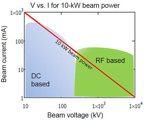
Figure 1. Operating beam current vs. beam voltage for a 10-kW electron beam as generated by a DC-based electrostatic accelerator (blue) and an RF-based linear accelerator (green). The red line indicates a constant beam power of 10-kW.
The development of RF-based particle accelerators for space missions dates back to the 1980s when Los Alamos National Laboratory successfully launched and operated a radio-frequency quadrupole (RFQ) accelerator aboard a rocket (O'Shea, 1990). The RFQ accelerated H− ion beams that were then neutralized to produce neutral hydrogen atom beams for the BEAR (Beam Experiment Aboard a Rocket) project as part of the Neutral Particle Beam program. RF linac use time-varying electric fields along the axis of a resonant RF structure consisting of a number of RF cavities to accelerate charged particle beams. An RF cavity is a hollow piece of electrical conductor enclosing an evacuated volume that stores electromagnetic energy in the form of time-varying electric field (pointing along the cavity axis) and magnetic field (circulating near the outer cavity walls). The two halves of an RF cavity made out of copper are shown together with an HEMT (small white square) mounted on a printed circuit board in Figure 2A. Typical amplitudes of the accelerating electric fields range from a few megavolts per meter (MV/m) for a low-gradient structure to more than 100 MV/m for a high gradient linac. In order to realize these high accelerating fields, RF linac have historically been driven by high-power RF sources, such as klystrons, that are capable of delivering 5–100 MW of RF power over the duration of a few microseconds. These high-power sources are large and heavy, and they require pulse forming networks and high-voltage (e.g., 50–100 kV) power supplies. The output of the source is typically shared between a large number RF cavities, depending on the particulars of the design. For our mission to deploy a compact and lightweight accelerator in space, we need a new source of RF power that eliminates the need for high voltages and bulky pulse forming network. Figure 2B shows the model of a 55-cavity, 1.7-m long accelerator that weighs about 127 kg including the weights of all low-voltage RF power sources and beam control systems.
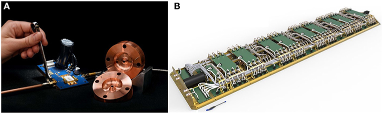
Figure 2. (A) Photo of two halves of a C-band cavity and an HEMT on a printed circuit board; (B) A compact 55-cavity, 1.7-m long, 1-MeV electron accelerator based on HEMT solid-state RF sources.
Compact RF power source now exists with the recent release of high-power solid-state RF amplifiers such as the Wolfspeed/Cree CGHV59350 high-electron-mobility transistors (HEMTs) (Cree, 2018). These HEMTs are capable of ~500 W of RF power each, and they can be used to power individual accelerating cavities with independent phase and amplitude controls (Lewellen et al., 2016; Nguyen et al., 2018). Our accelerator design differs from the more traditional approach of combining a large number of solid-state RF amplifiers into a high-power all-solid-state RF system (Di Giacomo, 2009). By using HEMTs for direct pumping without the power combiner and operating at relatively low accelerating gradient, we improve the efficiency of converting electrical power into electron beam power. The overall wall-plug efficiency for the HEMT-powered accelerator is estimated at 10% or greater. For the CONNEX experiment, to produce 1 kW of electron beam power (1 MeV at 1 mA average current), the accelerator is expected to have DC power consumption of 10 kW during a 10-s burst every 5 min. The average power consumption during a 4-h engagement is only about 500 W.
A New Concept for Electron Accelerators
Several factors need to be considered when selecting the accelerator technology for space applications: size, weight, power requirement (efficiency) and reliability of the accelerator system. Typical terrestrial RF linear accelerators consist of a string of either copper or niobium resonant cavities assembled in a continuous structure known as an accelerator module. Water-cooled copper accelerator modules operate at room temperature, driven by high-power klystrons or solid-state power-combined sources, and are temperature-stabilized to within a fraction of a degree C. Typical efficiency of converting electrical power to beam power is around 7% (Has Tajar et al., 2016). Niobium linear accelerator modules can approach 50% efficiency and can be driven by low-voltage, solid-state RF sources. However, the niobium cavities must be maintained below 4 K (liquid helium boiling point) to remain superconducting, and thus require a large and vibration-sensitive liquid helium cryoplant and cryomodules. Including the cryoplant power requirements, the wall-plug efficiency of superconducting accelerator modules is also usually in the single digits (Has Tajar et al., 2016). Both types of RF linac have significant size, weight, and power requirement as well as a single point of failure: the klystron and its high-voltage power supply for copper accelerators and the liquid helium cryoplant for niobium accelerators. Neither would be ideal for a space-borne accelerator.
In the past 3 years, Los Alamos National Laboratory has developed a new configuration of space-borne accelerators based on a new class of solid-state RF sources that are sufficiently small and lightweight to be deployed in space and that run on low-voltage power supplies. Our new concept of space-borne electron accelerators differs in several respects from conventional electron accelerator design, reflecting the very different environment in which it must operate. First, each accelerator cavity is individually powered by solid-state HEMTs serving as its own RF amplifier chain, and operates at relatively low gradients of 1–5 MV/m. Secondly, there is no active temperature stabilization. Instead, the cavity temperatures are allowed to rise during operation and the rates of temperature rise in individual cavities depend on the interior surface ohmic losses and the heat capacity of individual cavities. Thirdly, the cavity frequencies are monitored and adjusted with the use of active frequency control to allow the cavities to operate over a range of temperatures.
The new accelerator configuration has several operational benefits. First, using HEMTs as the RF amplifiers running on low-voltage DC power supplies eliminates the problems of operating high-voltage devices in space. Secondly, the system wall-plug efficiency can be much higher than conventional linear accelerators, because (a) no power is expended on active cooling of the accelerator cavities, and (b) the cavities operate at relatively low accelerating gradients allowing a greater fraction of the RF power to be delivered to the beam. Finally, the accelerator system is robust against failure of individual components due to the inherent modularity of the design. For instance, in a conventional accelerator a klystron failure will definitely lead to a system shutdown, whereas in the new modular design, the failure of a single HEMT would result in only a small reduction in the total beam energy.
A key feature of the new design is the low accelerating gradient and thus a higher fraction of the RF power going into the beam. As shown in equation 1 below, operating at low accelerating gradient (E0) and high beam current (Ib) reduces the RF power delivered to the cavity (the first term on the right-hand side of Equation (1) and increases the power delivered to the beam (the second term in Equation 1).
Here, PRF is the total RF power required, Rs is the shunt impedance of the cavity per unit length, Lcav is the cavity length, Vb is the voltage gain of the beam through the cavity, and Ib is the beam current. For illustration, let us consider an RF accelerator design capable of generating a 1 MeV, 10-mA beam operating at a 10% duty cycle (1 kW average power) as required to effectively probe the coupling between the Earth's magnetosphere and ionosphere (Marshall et al., 2014; Dors et al., 2017). If we select an accelerating gradient of 1.5 MV/m for the C-band cavity with 1.3 cm active length–the cavity length is chosen to match the average velocity of the sub-relativistic electrons throughout most of the cavities–then the cavity power (the first term of Equation 1) is about 300 W and the voltage gain per cavity is 20 kV. With 10 mA instantaneous current, the instantaneous beam power is 200 W, so 40% of the incoming RF power (~500 W) is converted into beam power. While the DC-to-RF conversion efficiency of individual HEMTs is at least 50%, since we have to use two HEMTs for each cavity due to their low gain, the DC-to-RF conversion efficiency drops to about 25% for the pair. Thus, the net efficiency of converting DC electrical power to beam power is 10%, which is still higher than a typical efficiency of terrestrial RF linacs.
A unique feature of the RF linac is its ability to produce a beam pulse format consisting of a series of pulses, minipulses and micropulses. For an RF linac operating at 5.1 GHz, the micropulses are separated by 0.196 ns, the inverse of 5.1 GHz. The length of the minipulses is set by the duration of the RF amplifier pulses, which for HEMTs is about 100 microseconds (us). During the 100-us minipulse, the beam power shall be 10 kW (1 MeV, 10 mA). Using the 25% DC-to-beam conversion efficiency, the DC power requirement for the space-borne accelerator would be 40 kW. The average power requirement would be lower since the HEMTs operate at 10% duty factor, i.e., the minipulses shall be on for 100 us and off for 900 us. The CONNEX mission requires an electron beam pulse, consisting of approximately fifty minipulses, that is sufficiently long (~0.5 s) to deposit a substantial amount of energy (~500 J) from the electron beam into the upper ionosphere to achieve good signal-to-noise ratio on the ground detectors.
The CONNEX accelerator design consists of a low-voltage DC electron gun, a buncher RF cavity, where the electron beam undergoes density modulations and forms short bunches, and 54 accelerating cavities assembled in nine groups of 6 cavities separated by focusing solenoids (Figure 3A). The first cavity acts as a “buncher” cavity to modulate the continuous electron beam from the DC electron gun into short bunches separated by one RF period. For most of the accelerator, the electron beam travels at sub-relativistic velocity, i.e., the particle velocity is much less than the speed of light. In a terrestrial RF linac, this would require adjusting the cavity length to match the velocity of the particle beam. In our space-borne accelerator, we shall fix the cavity to a length corresponding to the average beam velocity (about 0.4 times the speed of light). In operation, we shall adjust the RF phases of individual cavities such that the electron bunches arrive at the longitudinal center of the cavities when the accelerating field is at or near the maximum. This is made possible by using a low-level RF control system that independently phases the RF input to the HEMT amplifiers that power each individual cavity. Beam dynamics simulations using the GPT particle-pushing code (van de Meer and De Loos, 2001) show that 50% of the electrons from the DC gun are bunched, captured and accelerated continuously to 1 MeV with the use of this independent RF phase adjustment (Figure 3B). In addition to independent phase adjustments, the field amplitude of these cavities can also be independently controlled to maximize the capture efficiency and the total energy gain. The choice of fixed cavity length simplifies the cavity design and fabrication, and allows the heat load to remain the same for all cavities, an important feature when operating these cavities without active cooling as it simplifies the frequency stabilization.
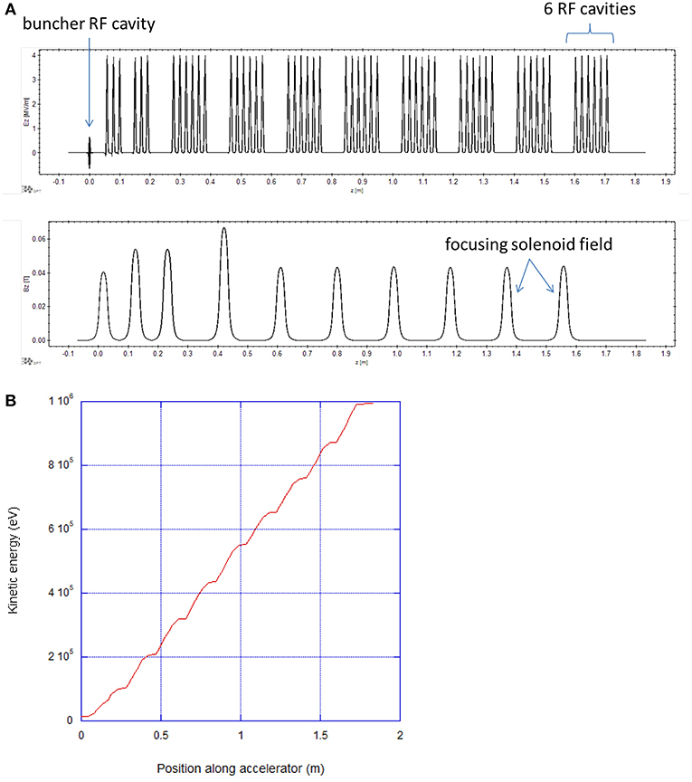
Figure 3. (A) Plot of accelerating field magnitudes of individual RF cavities and focusing solenoid fields along the accelerator; (B) plot of kinetic energy in eV vs. position along the accelerator.
Gallium Nitride High Electron Mobility Transistors
Wide-bandgap GaN-based HEMT are a new class of RF power devices that have recently found widespread use in wireless and satellite communication. These HEMT devices can also be used as high-power RF amplifiers over a broad range of radio-frequencies thanks to their large breakdown voltage and high electron velocity (Mishra et al., 2008). The fabrication of HEMTs typically involves growing GaN films via epitaxial layer growth on semi-insulating SiC substrates and then a thin layer of AlGaN is grown over the GaN film to form an AlGaN/GaN heterojunction (Figure 4A). Due to the different energy bandgap structures of AlGaN and GaN, large energy band bending occurs at the heterojunction, creating a potential difference that results in a flow of free electrons (Figure 4B) toward the underlying GaN, forming a two-dimensional electron gas (2DEG) (Lee, 2014). This high-density accumulation of free electrons, combined with the high polarization field at the sharp interface between AlGaN and GaN layers, is responsible for the high electron mobility in HEMTs.
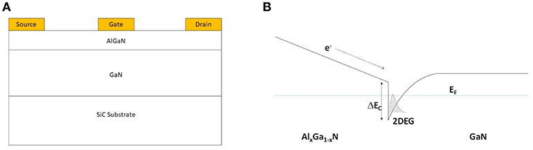
Figure 4. (A) Schematic of a typical GaN HEMT cross-section showing a thin (~20 nm) AlGaN layer and a micron-thick GaN layer grown on top of a SiC substrate; (B) The energy band structure of AlGaN/GaN showing the formation of the two-dimensional electron gas (2DEG) at the interface.
HEMTs can be constructed to operate over a broad range of frequencies, with center frequencies ranging from 1.2 to 9.6 GHz and bandwidths up to ~20%, and delivering RF power up to 700 W per device at 2–4 GHz. The RF power needed to drive a single accelerator cavity scales with the square of the accelerating field, inversely with the cavity shunt impedance per unit length (Rs) and proportionally with the cavity length, as shown in Equation 2.
We selected the Cree HEMTs at 5–6 GHz because these HEMTs provide the highest available RF power for the electron beam, defined as the difference between the HEMT output and the cavity power. The cavity power is calculated from the expected shunt impedance for copper cavities at different frequencies assuming 1 MV/m as the accelerating gradient in these cavities. The scaling of cavity shunt impedance (a measure of how efficiently RF cavities utilize RF power in establishing the cavity accelerating field), cavity length and cavity power with frequency is shown in Equations 3–5. The HEMT output and calculated cavity power for the frequency range 2–10 GHz is plotted in Figure 5.
The RF power available for the electron beam is the difference between the HEMT output power (Figure 5, red dots) and the cavity power (Figure 5, blue curve). As can be seen in Figure 5, the available RF power for the particle beams is greatest at the 5–6 GHz frequency band (C-band).
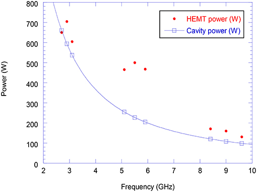
Figure 5. Plot of HEMT output power (red) and calculated cavity power (blue) vs. frequency.
To characterize the RF performance of commercial C-band HEMTs for accelerator operation, we set up a test fixture and measured the output power, small-signal gain and harmonic content of the HEMT output. The RF input with amplitude of about 0 dBm (1 mW) was generated by a low-noise continuous-wave (CW) network analyzer followed by an RF switch to produce low-amplitude RF pulses, with duration up to 500-us and repetition rates up to 600 Hz, to be amplified in the preamp with 40–50 dB gain. The 40-W output from the preamp was amplified in a GaN HEMT with 10 dB small-signal gain to produce 400 W of RF power. Figure 6 shows the schematic of the HEMT RF accelerator performance characterization set-up. The combination of pulse duration and repetition rate allowed us to explore HEMT performance up to 30% duty factor, three times higher than the nominal rating of the device.
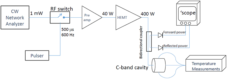
Figure 6. Schematic of the HEMT RF accelerator performance characterization.
The output power from a single HEMT is plotted vs. the network analyzer power in dBm in Figure 7A, showing linear response over a range of input power until the output is saturated at about 400 W. At saturation, the single-pass gain of the HEMT is only 10 dB which requires us to have two GaN HEMTs operating in series for each cavity. Figure 7B shows the typical waveform of a 500-μs RF pulse from the HEMT. The HEMT output pulse shows a power drop from ~550 W at the leading edge to ~400 W at the trailing edge. We have not ascertained the cause of this power drop. However, we expect the HEMT output power to depend on temperature of the AlGaN/GaN junction; as the output power exceeds 500 W, the AlGaN/GaN junction temperature rises. The AlGaN/GaN HEMT drain current has been shown to drop as a function of junction temperature and one expects the output power to also decline at high temperature (Wang et al., 2013).
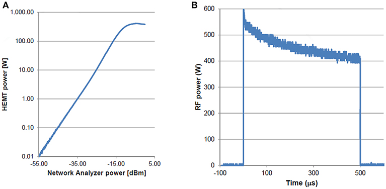
Figure 7. (A) Plot of HEMT output power vs. the network analyzer power in dBm; (B) a typical 500-us waveform of the HEMT output showing ~30% power drop.
Several aspects of HEMT performance are of particular concern for space-borne applications. These include basic performance (power output, small signal gain, etc.), operating in low-power-consumption modes, and power drop over the pulse. The nominal requirement for a single cavity for the CONNEX project is the acceleration of a 10-mA beam through a 20-kV gap; thus 200 W of RF is needed for the electron beam power per cavity. Using Equation 2 and the measured shunt impedance of the C-band cavity, we estimate approximately 250 W of cavity power is needed to generate the required 20-keV acceleration, so each cavity will require a total of 450 W of RF power. The nominal minimum output of the HEMT is 350 W; in practice, we find HEMTs can usually produce 450 W even when operated at 50 V DC, the lower end of their operating range.
We tried to maximize the HEMT output power by adjusting the drain-source voltage (Figure 8A). As the drain-source voltage was increased from 40 to 90 V, the HEMT output power rose to a maximum of 610 W at 65 V and then decreased at higher drain-source voltage. We also tried to reduce the HEMT quiescent current (thus improving the average efficiency) by operating the HEMT at two sub-threshold gate bias voltages. At gate bias voltage more negative than −3.7 V, the quiescent current decreased to zero, and the HEMT power draw was zero without RF. As we increased the input RF power to 35 dBm, the HEMT generated power with 10 dB small-signal gain at −3.7 V gate bias voltage (Figure 8B). At −5 V bias voltage and high input power, the small-signal gain rose to more than 9 dB if the input RF power exceeded 44 dBm. These results suggest that the HEMT output power and efficiency can be improved by optimizing the drain-source and gate bias voltages.
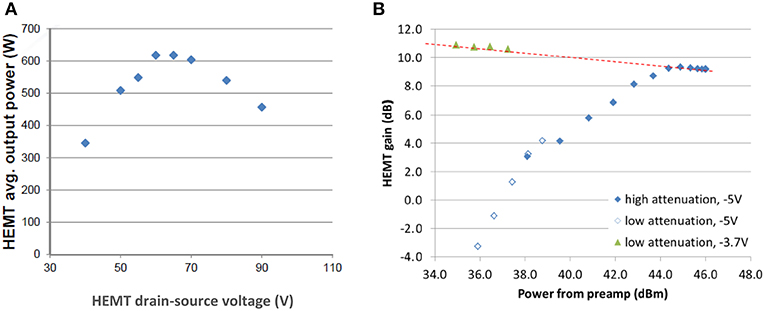
Figure 8. (A) Plot of HEMT output power vs. HEMT drain-source voltage; (B) HEMT gain at two different gate bias voltages, −3.7V and −5V, both below the threshold to turn on the HEMT.
Initial Accelerator Operation and Energy Measurements
Calorimetric Measurements
We operated the single-cavity accelerator without active cooling for extended durations, measured the absorbed RF power and compared the results with RF measurements. The cavity temperatures were plotted vs. time (Figure 9, blue curve) and from the temperature rise, we estimated the RF power absorbed in the cavity using a calorimetric model. As the cavity resonant frequency shift is inversely proportional to the temperature rise, the RF source frequency was also varied to track the cavity frequency. In our simple calorimetric model, the rate of cavity heating due to the average RF power absorbed in the cavity is the sum of two terms: (1) the rate of heat causing the cavity temperature to rise, i.e., the cavity heat capacity term, and (2) the heat loss due to conduction to the surroundings, which is expressed as the inverse of the thermal resistance. The average RF power absorbed in the cavity is given by Equation 6,
where θ is the difference between the current and initial temperatures, θ = T − Tini, m is the copper cavity mass, Cv is copper heat capacity and RT is the thermal resistance. The thermal resistance is calculated from the thermal decay time constant τ, defined as τ = mCvRT, which can be extracted from the temperature decay curve (Figure 9) after the RF power was turned off.
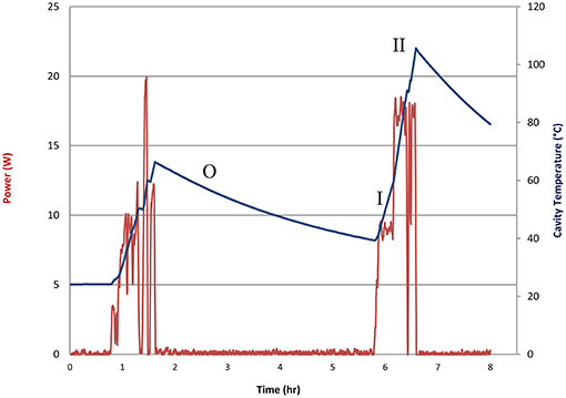
Figure 9. Plots of average RF power (red) and cavity temperature (blue) as functions of time. The time period O corresponds to no RF power; I corresponds to RF on at 5% and II at 10% duty factor.
Based on the temperature decay after RF power was turned off (time period O), we calculated a decay time constant of τ = 13, 064seconds = 3.629 hours.From the cavity mass and heat capacity, the calculated thermal resistance is RT = 28.78°C/W. From Equation 6, we calculated the average RF power deposited into the cavity from the rate of temperature rise and the thermal resistance. During the two time periods labeled I and II in Figure 9, the HEMT duty factor was 5% (region I) and 10% (region II), and the calculated average power delivered to the cavity was 8.5 W (region I) and 17 W (region II). These average power measurements translate into a peak value of absorbed RF power of 170 W for both regions.
Temperature-Dependent Frequency Shift
As described above, the space-borne accelerator will not have temperature stabilization, so all cavities must be maintained at the same frequency with active frequency control. We measured the resonant frequency of a C-band cavity as it was powered with 170 W at 5 and 10% duty factors without water cooling. As the cavity temperature rose by 65°C in 48 min, its resonant frequency decreased by 5.7 MHz (−88 kHz/°C) at an average rate of 2 kHz/s. To compensate for the temperature-induced frequency shifts, we designed a piezo tuner to be inserted into the cavity which would reduce the cavity inductance and thus shift the cavity resonant frequency to a higher frequency. The measured and CST-modeled cavity resonant frequency shifts vs. piezo tuner displacement in the cavity is shown in Figure 10. The range of piezo movement needed to compensate for the 5.7 MHz frequency shift due to the cavity temperature rise of 65°C is <4 mm. We have found that both copper and aluminum make good material for the tuner as they preserve 99% of the cavity quality Q at the largest tuner displacement. In space, the accelerator will be mounted on a temperature-controlled surface and operated at approximately the same location in its orbit such that the temperature of the accelerator during operation will be between 15° and 25°C.
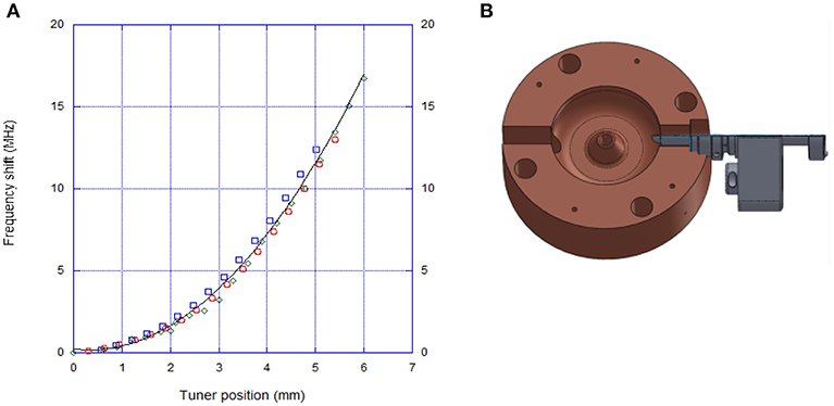
Figure 10. (A) Cavity frequency shift vs. tuner position for two separate sweeps of the tuner (blue and green markers) and CST simulation results (red markers) superimposed with the fit of all three data; (B) Solid model of the cavity with a section view of the piezo tuner.
Energy Gain Measurement
The single-cavity energy gain was measured using the experimental setup illustrated in Figure 11A. A low-current 20-kV DC beam from a commercial Kimball Physics electron gun was passed through a prototype C-band cavity (labeled C in Figure 11B) powered with a single HEMT at various power levels. The deflection of the beam by a fixed-field dipole spectrometer (labeled D in Figure 11B) is proportional to the beam momentum, allowing measurement of the energy gain delivered to the beam.
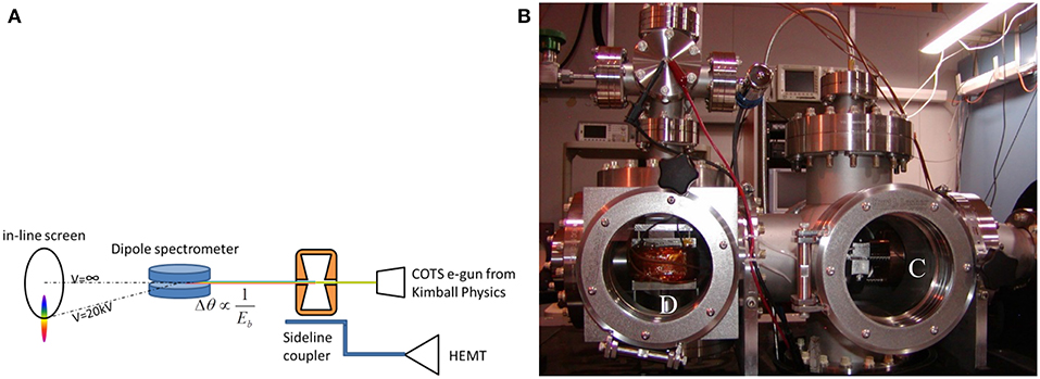
Figure 11. (A) Schematic of the single-cavity energy gain measurement. The deflection angle is inversely proportional to the momentum of the electron beam; (B) Photo of the single-cavity energy gain measurement with the cavity (labeled C) mounted immediately after the Kimball-Physics electron gun (to the right of this picture), and the dipole spectrometer (labeled D).
With low-power RF delivered to the cavity, the DC electron beam experienced weak bidirectional energy shifts, i.e., energy modulations, and the energy gain was measured at the maximum energy of the energy-modulated beam on the screen. Figures 12A–C show images of the electron beams with no energy modulation (a), weak energy modulation with low cavity RF power (b) and strong energy modulations with medium RF power (c).
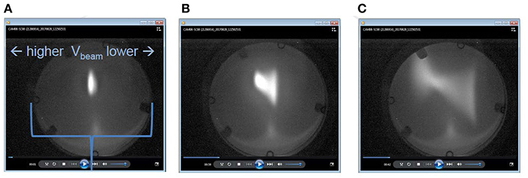
Figure 12. (A) Position of the incoming electron beam on the screen with cavity RF off; (B) Energy-modulated electron beam with weak energy modulation at low RF power; and (C) Energy-modulated beam with strong energy modulation at medium RF power.
At even higher RF power (and thus higher energy gains), we were able to detect a well-defined beam on the screen corresponding to those electrons that are accelerated at the peak of the RF field. Since only a small fraction of the incoming electrons are at the peak of the RF field, the maximum-energy beam spot (Figure 13B) is dimmer than the incoming DC beam spot (Figure 13A).
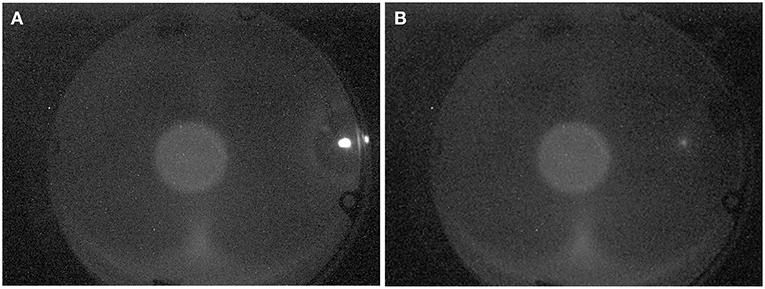
Figure 13. (A) Position of the incoming electron beam with the cavity RF power turned off; (B) Position of the beam with cavity power turned on (the beam intensity was dimmer because only a small fraction of the incoming electrons were accelerated to the maximum energy).
With the dipole turned off (and degaussed) and the cavity RF off, we established the “zero” position of the incoming DC beam on the screen. This zero position was approximately centered on the round image of the faint cathode glow on the screen. Then, with RF power to the cavity still off, we adjusted the dipole field such that the incoming electron beam at 20 kV (called the 20-kV zero), or at 30 kV (called the 30-kV zero), impacted at the edge of the screen (Figure 13A). This calibrated the combination of dipole field and drift distance to displacement on the screen for a known beam energy. Next, as we increased the cavity RF power, the beam moved toward the center (Figure 13B) and the beam's angular movement was used to determine the energy gain provided by the cavity.
The energy gain in an RF cavity is a product of the accelerating field and the transit-time corrected cavity length. Since the accelerating field is proportional to the square root of the RF power, the energy gain can be expressed by Equation 8.
Figure 14 shows the measured (red circles) and calculated (blue line) energy gain as a function of the cavity power. While the HEMT was operating at ~530 W, the cable connecting it to the cavity (inside a shielded enclosure) imposed ~3 dB attenuation, limiting our maximum power to the cavity to 264 W. From the fit of the measured energy gain vs. the cavity power, we estimated the product of the shunt impedance per unit length (Rs) and the effective length (Lcav) of our C-band cavity to be 1.6 ± 0.1 MΩ.
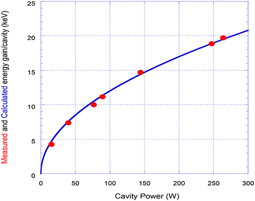
Figure 14. Plot of measured (red circles) and calculated (blue line) energy gain vs. cavity power.
We experimentally measured the beam energy gain as a function of RF power levels via three different methods: (1) By measuring the deflection of the incoming 20-kV beam from the screen edge as a function of cavity power (the 20-kV-zero method); (2) by measuring the deflection of the incoming 30-kV beam from the screen edge as a function of cavity power (the 30-kV-zero method); and (3) by measuring the cavity RF power needed to move the 20-kV beam from its zero position to the position of the 30-kV beam (the 20-30-kV-delta method). The beam kinetic energy gains measured by these three methods are plotted vs. the square root of cavity power in Figure 15.
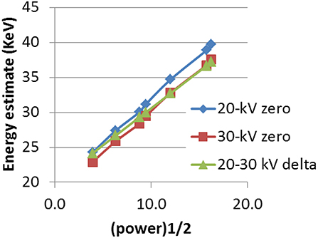
Figure 15. Beam kinetic energy vs. RF input power using a 20-kV calibration (blue line), a 30-kV zero calibration (red line) and a third calibration using the power required to move the beam between the 20-kV and 30-kV calibration positions, for a fixed dipole field (green line).
Conclusion and Future Plan
We have demonstrated key aspects of technology required for the development of space-borne electron linacs. These include RF power source characterizations, tuner design, and beam acceleration with energy gain measurements. These initial test results show that HEMTs, operating with 50 V DC power supplies, can deliver sufficient RF power to individual accelerator cavities to provide energy gain of 20 keV per cavity. Raising the energy of the electron beam to 1 MeV will require approximately fifty of these C-band cavities, with each cavity powered by its own HEMTs and operated without water cooling. Compared to traditional klystron-based designs, the HEMT-powered linac design is more compact, efficient and suitable for space missions. It also avoids the use of high-voltage klystrons and associated power supplies which have been the single-point failures of terrestrial RF linacs. Currently, our team is concentrating effort on testing a multi-cavity prototype with the goal of accelerating the electron beam continuously in these cavities to a higher beam energy. The prototype will make use of an improved cavity design and an RF system that mimics a flight-appropriate system as closely as possible. As these cavities are physically independent, we may explore the possibility of using the first cavity as the buncher cavity, i.e., the first cavity will be used to modulate the energy of the incoming DC electron beam. The energy-modulated electrons will form short bunches of electrons at the cavity resonant frequency after drifting a short distance and these electron bunches will be captured and accelerated in the subsequent RF cavities. The phase and amplitude of the RF cavities can be independently adjusted to improve the fraction of electrons captured by the cavities. Finally, the multi-cavity prototype will allow exploration of various low-level RF control algorithms for maintaining cell-to-cell frequency and phase stabilization.
Author Contributions
JL provided the physics design, performed all experimental work and analyzed the data. CB provided engineering designs, set up the beam experiment and assisted with the experimental work. BC was responsible for the first iteration of the CONNEX accelerator design. GD performed the initial HEMT tests and evaluation. MH and DP performed most of the HEMT testing and provided engineering support to the experiments. SS developed the engineering model of the CONNEX MeV space-borne accelerator. DN originated the concept, provided technical leadership, interpreted the data and prepared the manuscript with help from the co-authors.
Funding
Research presented in this article was supported by the Laboratory Directed Research and Development program of Los Alamos National Laboratory under project number 20170521ER.
Conflict of Interest Statement
The authors declare that the research was conducted in the absence of any commercial or financial relationships that could be construed as a potential conflict of interest.
Acknowledgments
The authors are grateful to the SLAC National Accelerator Laboratory team led by Jeffrey Neilson for the accelerator cavity design and numerous accelerator/injector physics discussions, and the Magnetosphere-Ionosphere Connections (CONNEX) satellite team led by Eric Dors for close collaborations and many fruitful discussions.
References
Cohen, H. A., Adamo, R. C., Aggson, T., Chesley, A. L., Clark, D. M., Damron, S. K., et al. (1980). “P78-2 satellite and payload responses to electron beam operations on March 30, 1979,” in NASA Conference Publication 2182–Spacecraft Charging Technology. (Colorado Springs, CO), 1980, 509–559.
Cree (2018). CGHV59350 Data Sheet, 350 W, 5200-5900 MHz GaN HEMT for C-Band Radar. Available online at: https://www.wolfspeed.com/downloads/dl/file/id/463/product/174/cghv59350.pdf (accessed May 29, 2018).
Di Giacomo, M. (2009). “Solid-state RF amplifiers for accelerator applications,” in Particle Accelerator Conference (PAC09), paper TU4RAI01. (Vancouver, BC).
Dors, E. E., MacDonald, E. A., Kepko, E. L., Borovsky, J. E., Reeves, G. D., Delzanno, G. L., et al. (2017). “CONNEX: Concept to Connect Magnetospheric Physical Processes to Ionospheric Phenomena,” in Active Experiment in Space: Past, Present and Future Workshop (Santa Fe, NM).
Has Tajar, M., Méot, F., and Peggs, S. (2016). “Energy Efficiency of High Power Accelerators for ADS Applications,” in Proceedings of IPAC2016, paper TUPOY044 (Busan).
Hendrickson, R. A., McEntire, R. W., and Winckler, J. R. (1975). Echo 1: an experimental analysis of local effects and conjugate return echoes from an electron beam injected into the magnetosphere by a sounding rocket. Planet. Space Sci. 23, 1431–1444. doi: 10.1016/0032-0633(75)90039-2
Hendrickson, R. A., Winckler, J. R., and Arnoldy, R. L. (1976). Echo iii: a study of electron beams injected into the auroral ionosphere. Geophys. Res. Lett. 3, 409–412.
Lee, D. S. (2014) Deeply scaled GaN high electron mobility transistors for RF applications Thesis, Massachussetts Institute of Technology, Dept. of Electrical Eng. and Computer Science, 2014 (Cambridge, MA).
Lewellen, J. W., Buechler, C., Dale, G., Moody, N. A., and Nguyen, D. C. (2016). “Spaceborne electron accelerators,” in Proceedings of LINAC2016, paper MO3A03 (East Lansing, MI).
Lucco Castello, F., Delzanno, G. L., Borovsky, J. E., Miars, G., Leon, O., Gilchrist, B. E., et al. (2017). Spacecraft-charging mitigation of a high-power electron beam emitted by a magnetoscpheric spacecraft: Simple theoretical model of the transient of the spacecraft potential. J. Geophys. Res. Space Phys. 123, 6424–6442. doi: 10.1029/2017JA024926
Marshall, R. A., Nicolls, M., Sanchez, E, Lehtinen, N. G., and Neilson, J. (2014). Diagnostics of an artificial relativistic electron beam interacting with the atmosphere. J. Geophys. Res. Space Phys. 119, 8560–8577. doi: 10.1002/2014ja020427
Mishra, U. K., Shen, L., Kazior, T. E., and Wu, Y. F. (2008). GaN-based rf power devices and amplifiers. Proc. IEEE 96, 287–305. doi: 10.1109/jproc.2007.911060
Nguyen, D. C., Buechler, C., Dale, G., Dolgashev, V., Fleming, R, Jongewaard, E., et al. (2018). “The path to compact, efficient solid-state transistor driven accelerator,” in Proceedings of the 9th International Particle Accelerator Conference, IPAC2018, paper MOPML052. (Vancouver, BC).
Obayashi, T., Kawashima, N., Kuriki, K., Nagatomo, M., Ninomiya, K., Sasaki, S., et al. (1982). “Space experiments with particle accelerators (SEPAC),” in Artificial Particle Beams in Space Plasma Studies, (Boston, MA: Springer). 659–671.
O'Shea, P. G. (1990). “A linear accelerator in space - the Beam Experiment Aboard Rocket,” Proceedings of the 1990 Linear Accelerator Conference, (Albuquerque, NM), 739–742.
Sasaki, S., Kawashima, N., Yanagisawa, M., and Obayashi, T. (1986). Vehicle charging observed in sepac spacelab-1 experiment. J. Spacecr. Rockets 23.
van de Meer, B., and De Loos, M. (2001). The General Particle Tracer code, Design, Implementation and Application, PhD Thesis: Eindhoven University of Technology.
Wang, Y.-H., Liang, Y. C., Samudra, G. S., Chang, T. F., Huang, C. F., Yuan, L., et al. (2013). Modelling temperature dependence on AlGaN/GaN power HEMT device characteristics. Semicond. Sci. Technol. 28:125010. doi: 10.1088/0268-1242/28/12/125010
Keywords: electron accelerators, space-borne accelerators, radio-frequency linac, high electron mobility transistors, particle beams in space, magnetosphere, ionosphere
Citation: Lewellen JW, Buechler CE, Carlsten BE, Dale GE, Holloway MA, Patrick DE, Storms SA and Nguyen DC (2019) Space-Borne Electron Accelerator Design. Front. Astron. Space Sci. 6:35. doi: 10.3389/fspas.2019.00035
Received: 30 January 2019; Accepted: 23 April 2019;
Published: 15 May 2019.
Edited by:
Evgeny V. Mishin, Air Force Research Laboratory, United StatesReviewed by:
Alexei V. Dmitriev, Lomonosov Moscow State University, RussiaArnaud Masson, European Space Astronomy Centre (ESAC), Spain
Copyright © 2019 Lewellen, Buechler, Carlsten, Dale, Holloway, Patrick, Storms and Nguyen. This is an open-access article distributed under the terms of the Creative Commons Attribution License (CC BY). The use, distribution or reproduction in other forums is permitted, provided the original author(s) and the copyright owner(s) are credited and that the original publication in this journal is cited, in accordance with accepted academic practice. No use, distribution or reproduction is permitted which does not comply with these terms.
*Correspondence: Dinh C. Nguyen, ZGNuZ3V5ZW5AbGFubC5nb3Y=