 Angela D. V. Di Virgilio
- Istituto Nazionale di Fisica Nucleare (INFN) Pisa Section, Pisa, Italy
Large-frame optical Sagnac gyroscopes, more commonly called ring laser gyroscopes, are considered the only device able to provide fast and very high sensitivity measurement of the length of the day (LOD) and of the Earth rotation axis variations. Several large-frame Sagnac gyros are presently operative with a high duty cycle and a sensitivity well below fractions of nrad/s in 1 s measurement. At present, other inertial angular rotation sensors are not competitive with ring laser gyroscopes. The feasibility depends on the so-called hetero-lithic ring lasers. The present state of the art is reported and the feasibility of the main goals for geodesy discussed.
1. Introduction
More than 100 years ago, the French physicist Georges Sagnac, in his research aimed at the discovery of the ether, found an effect of special relativity (now usually referred to as the Sagnac effect): the interference of two beams counter-propagating in a closed path attached to a frame is proportional to the rigid rotation of the frame (Sagnac, 1913a,b; Post, 1967). The discussion of how to correctly interpret Sagnac's experiment is interesting (Pascoli, 2017). The Sagnac effect has had, and still has, a large impact on inertial navigation, and it is relevant for GNSS (ESA, 2020) and fundamental physics tests in space (Spallicci et al., 1997). The family of inertial angular rotation sensors based on the Sagnac effect (SG) is rather large. These can be based on atoms or light; if the latter, there are devices based on optical fibers (FOG) and others based on resonant ring cavities. This last group is further divided in two: passive ring cavity (PRC) and active ring cavity, also called ring laser gyro (ARC or RLG). PRC and RLG are based on the same apparatus: in one case the laser light is injected from the outside, while the other contains an active medium and operates as a laser with two counterpropagating modes. The same apparatus could in principle be operated as active or as passive, and this is a very interesting feature for very high sensitivity measurements to get rid of the systematic. The scale factor of any SG depends on its geometry. General Relativity is necessary to fully describe the Sagnac effect and, for that we refer to, the work of Tartaglia et al. (2017), the main result can be seen in section 3. Here, we refer to the classical relationship, which in general is proportional to the ratio , where λ is the wavelength of the light and A the area enclosed by the ring path:
where c is the velocity of light, the normal vector upon the area, and the rate of rotation of the device. The situation is a bit different in the case of the RLG and PRC; here, it is proportional to the , where L is the perimeter of the ring and the ring an optical cavity. Equation (2) reports the general classical mathematical expression linking the Sagnac frequency of RLG and the angular rotation rate:
where ζ is the angle between of the RLG and the absolute orientation of the angular velocity of the apparatus (Ω being the modulus of the angular velocity). Any geometry or orientation change affects the response of the apparatus. For this reason, the details of the experimental apparatus matter in the final sensitivity and in general in its long time response. Besides that, it is very important to note that fs is the difference in frequency, induced by the rotation to the two counterpropagating modes; fs is quite often confused with the beat note fm between the two modes taken at the output of the RLG. The two quantities fs and fm are not equal, and other effects, mainly coming from the laser dynamic (which is non-linear), must be taken into account. The relation of the Sagnac effect taking into account the GR terms (Tartaglia et al., 2017), the main ones being the de Sitter and Lense-Thirring effects, is reported in subsection 3. The highest sensitivity sensors are lasers with ring cavities (laser ring or gyro-laser) and have perimeters from a few meters up to tens of meters. They have a record of sensitivity, response speed, and long-term stability. The most sensitive laser gyroscope currently active is G, 16 m perimeter (2001), of the Wettzell geodetic station in Bavaria. G was built almost 18 years ago to study the fast variations of the Earth rotation rate. Any RLG attached to the Earth crust is affected mainly by ; it is based on a monolithic design utilizing a block of Zerodur1, in practice the geometrical scale factor is constant by construction. Since this design cannot be further extended and cannot be utilized to form an array, the subsequent large base RLGs are based on hetero-lithic HL designs2. Examples of HL prototypes are GINGERINO, 14.4 m perimeter (2015), located inside the INFN laboratory of the Gran Sasso since 2015, and ROMY, 36 perimeter (2017), Schreiber et al. (2018) located in the seismological observatory of Bavaria, the first tri-axial observatory. A similar project has been recently funded in China, at HUST, Wuhan, but they are developing passive gyros with an HL design (Liu et al., 2019). Three sensors are the minimum number needed to reconstruct the three components of the rotation. RLGs can be oriented at will, and it is natural to develop arrays of RLGs. In 2011, we proposed the GINGER project to measure the Lense-Thirring effect with and array of RLG (Bosi et al., 2011; Di Virgilio et al., 2017; Tartaglia et al., 2017) in an Earth-based experiment. As shown in subsection 3, fs contains additive terms due to GR, in particular with the Lense-Thirring effect, and the confrontation of the measured fs with the measurement of Earth rotation rate carried out by the international system IERS gives us the opportunity to measure the Lense-Thirring effect on Earth. It is important to note that the Lense-Thirring effect has been measured in a space-based experiment (Ciufolini and Pavlis, 2004; Everitt et al., 2011; Ciufolini et al., 2016; Lucchesi et al., 2019), but the measurement of GINGER is not an averaged one and does not require a precise map of the gravity field. GINGERINO was built to validate the underground site of the Gran Sasso INFN laboratory for GINGER; at present, it is the only ring laser of great operational sensitivity in a seismically active area in the Mediterranean region, and it is able to operate with more than a 95% duty cycle and sensitivity of fractions of nrad/s in 1 s. Not only has it given unique information for geophysics since it is located in a very important seismically active area, but it has also provided a large amount of data in a very stable environment, demonstrating a possibility to improve the comprehension of the instrument, with special attention to the influence of laser dynamic.
The principle upon which the Sagnac effect is based may be exploited both for practical and for fundamental physics purposes. As for pure science, there are a number of activities under development: for example, GINGER has recently been proposed for Lorentz violation tests (Moseley et al., 2019). Moreover, there are also some proposals for measurements to be performed in space. In fact, the difference between right- and left-handed times of flight for electromagnetic waves traveling along a closed path gives information, first of all, on the absolute rotation (with respect to the “fixed stars”) of the device, such as the practical applications on vehicles or the use for dynamic geodesy and precise determination of the length of the day. However, the asymmetry of the propagation accounts also for the structure of the space-time in which the light moves. In particular, it is related to the spinning of the source of gravity, be it the Earth, the Sun, or even the Milky Way. Experiments evidencing this kind of phenomenon may be planned for testing, verifying, or disproving the General Relativity theory. While GINGER pursues these objectives on Earth, proposals of measurements in space that are all based on a Sagnac-like approach involve the Lagrange points of the Sun-Earth pair and the Galileo constellation around the Earth. The idea of the use of the Lagrange points (L-points) is based on the fact that such points accompany the Earth in its orbit around the sun, keeping a fixed configuration; putting transponders in three of the L-points (L4, L2, and L5) therefore draws a triangle (a closed circuit) at the scale of the inner solar system. This is the content of the LAGRANGE proposal (Tartaglia et al., 2018); the experiment would give information about the angular momentum of the Sun, but it could also put upper limits on the angular momentum of the Milky Way and, interestingly, on that of its dark matter halo (Tartaglia, 2018, 2019). Another proposal considers a triangle made of three satellites of the Galileo constellation, two located in an orbital plane and one in a different orbital plane; such configuration would give rise to an enclosed area changing in time and to a cyclically oscillating orientation of the plane of the triangle with respect to the galactic plane. In practice, a modulation would be introduced enabling the experiment to single out the galactic contribution from other components of the signal (Ruggiero and Tartaglia, 2019).
In the following a brief history of RLG will be reported, with details on fundamental physics and geophysics. The main expected objectives for geodesy are reported, and, at the end the sensitivity limits, the main problem on the reconstruction of the array and the importance of the reconstruction of the Sagnac signal taking into account the laser dynamic are discussed. Some of the most recent results of GINGERINO will be discussed.
It is important to say that sections 3 and 6 are simplifications extracted of our previous work (Di Virgilio et al., 2017), which contains calculations to find the specifications of the GINGER project designed for the Lense Thirring test; we have decided to report here those calculation with some simplification and making it more uniform with the present paper since they are straightforward mathematical calculations, but it is rather important to understand the key points and the requirements to combine the signals of RLG arrays keeping the shot noise limit. Our previous work was aimed at providing a full description of the requirements for GINGER as far as the GR test is concerned, while this paper is only focusing on providing the present status of art of RLG focusing on applications for geodesy and near future prospects.
2. A Bit of History and Link With Fundamental Physics and Geophysics
The light is the simplest probe we have in nature: extremely fast with constant speed and no coupling with the outside world nor with nearby masses. Moreover, it can be easily handed with mirrors and optical devices, and it is at the base of most very high-sensitivity meterological devices. The success of instrumentation based on light is at present in front of our eyes: VLBI, gravitational waves interferometers and optical interferometry in general, highly stabilized laser to build atomic clock that can measure gravity by gravitational red-shift just to give a list of top sensitivity apparatus, but the list could be much longer adding the use of light in everyday life. A comparison of two light beams that have followed a closed path in two different directions was used at the end of the nineteenth century for the intensive search of the ether. Certainly, it was not simple for Geoge Sagnac to observe the interference of two light beams counterpropagating in a closed path on 0.86 m2, rotating with 2 Hz rate, but he succeeded and observed the interferogram of 0.07±0.01 fringes, a shift that was directly proportional to the rate of rotation. His observation, universally referred to as the Sagnac effect, was the first evidence of the non-reciprocity of the time of flight of two photons count-propagating in a closed path.
Equation (1) reports the proportionality between the phase difference and the absolute rate of rotation of the entire apparatus, showing that this effect can be used to develop gyroscopes. Based on this, the optical path has been created by optical fibers or mirrors; in the first family, very long fibers are utilized in order to increase the response of the device, and in the second family, the mirrors are arranged in order to form a Fabry-Perot cavity. In this case the response follows Equation (2), and the scale factor is a bit different since it contains the ratio area over perimeter and not the only area. This simple fact is rather important for very high sensitivity applications; for a given required long-term stability, for example, to measure Ω with relative accuracy 1 part 1010 since the scale factor is a multiplicative factor, it must be stable up to 1 part 1010, assuming that λ can be measured with very high accuracy, in the case in which it depends on L. It is, however, necessary to keep it constant up to this level, which is rather demanding for large rings, while in the case in which the ratio A/L matters, it has been shown that it is possible to find a saddle point, and the control of the geometry can be relaxed (Santagata et al., 2015; Di Virgilio et al., 2017). In this section, it is important to remember that small size ring lasers have application in inertial navigation, and this kind of device is still produced, though at present FOG probably have larger diffusion.
It is absolutely necessary to cite the very important work of Jeffrey Stedman (Canterbury University, Christchurch, New Zealand) for the development of high-sensitivity ring laser gyros, work that has been completed later on by Karl U. Schreiber (TUM, Technical University of Munich, Germany). The importance for fundamental physics has been clear since the beginning, and the first experiment for the Lense Thirring test was proposed in the 1980s (Scully et al., 1981); however, the sensitivity has come close to the required sensitivity only in the last 10 years.
2.1. Link With Geophysics
The surface of the Earth moves with the passage of seismic waves generated by Earthquakes or by the interaction between the fluid component and the solid component of the planet as well as the effect of the dynamics of its interior. The complete description of the motion of a continuous medium requires at least six components, three linear and three rotational (there are also six component of strain). Traditionally, due to the greater difficulty inherent in their measure, the latter have generally been neglected by seismology, despite clear observations of their effect on buildings and geological structures have long been known. Completing the observation on all the six degrees of freedom would lead to progress in understanding the internal dynamics, the origin of the noise field generated by the Earth's ocean, and in general on inverse seismic problems aimed at reconstructing the structure and the source (Takeo and Ito, 1997; Cochard et al., 2006; Igel et al., 2007); as it would allow to better represent the wave field by analyzing components of the ground motion, otherwise ignored in the normal seismological modeling, but which could have non-secondary effects. Last but not least, it has been demonstrated that the use of rotational components allows to obtain direct measurements of the phase velocity of seismic waves (Cochard et al., 2006; Igel et al., 2007; Simonelli et al., 2018). As a result, it would allow to address in a complete new way seismological problems related to natural risks and for geophysical exploration. Rotational seismology is becoming a reality thanks to the development of suitable sensors, such as optical gyroscopes based on the Sagnac effect, which are very widespread and produced on an industrial level mainly for air, sea, and submarine navigation. Geophysical applications have required the development of more sensitive tools. There are two categories: portable sensors of relatively low sensitivity or very high-sensitivity sensors fixed permanently to the ground. The portable sensors are predominantly modified submarine navigation sensors.
3. The RLG Signal Expressed With the GR Terms
Since large based RLGs are mainly sensitive to the Earth rotation rate and we deal with an array, in the following the discussion will be extended to 2 RLGs, 1 and 2, with area versors in the meridian plane and dominant angular rotation term3. The calculations are done in two dimensions in order to simplify the calculations and since the GR terms are seen by the RLG as vectors contained inside the meridian plane.
Let us consider two RLGs defined by the area versors . As shown in Figure 1 the area versors of the two RLGs are and , ζ is the angle between and , and γ is the angle between and , which can be independently measured. The two indices can be interchanged.
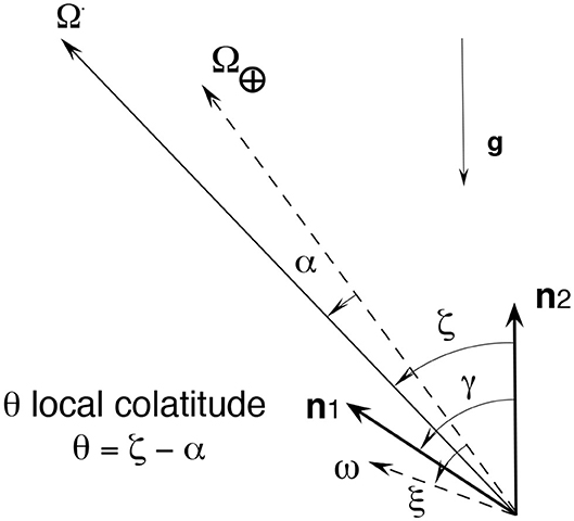
Figure 1. Pictorial view of the geometrical quantities: RLGs versors, the angular rotation vectors, and the main angles. The total angular rotation vector is the sum of two different vectors , the Earth angular rotation, and . The angles are positive with the convention expressed by the small arrows, and the RL2 is horizontal ( is vertical). The versors of the two RLGs, and are shown with thicker lines, the main angles ζ, γ, α, and ξ are shown, the angle α is the angle between and , while ξ is the angle between and . Adapted from Tartaglia et al. (2017) under the Creative Commons CCBY license.
The GR components depend on the ratio of Schwarzschild radius to the radius of the Earth (parameter ) and on its dimensionless moment of inertia (parameter ), accordingly for example the RLG, output Sagnac frequency f2 is expressed in function of a and b as
where the absolute value bars | have been introduced just to remember that the frequency is always a positive quantity; and β is the angle between and , β = ζ − α following Figure 1. The angle α is defined in GR (Tartaglia et al., 2017), and it is α = (a − 3) cos θ sin θ; taking into consideration that α = η⊥, and evaluating η∥ from Equation (3), it is possible to write
It is therefore possible to evaluate a and b if η⊥ and η∥ are evaluated from the experiment4, obtaining
From the numerical value of a and b, it is possible to show that of the GR terms gives and or, equivalently, η ~ 8.82 · 10−10 and ξ ~ 23.37°. If only the LT effect is taken into account, we obtain and or, equivalently, η ~ 3.64 · 10−10 and ξ ~ 71.56°. The procedure is valid if only the LT test is required; in this case, the de Sitter term, which is in principle well-known (Everitt et al., 2011), should be summed to the measurement of Ω⊕ done by IERS. It can be demonstrated that, with a single array and with the independent measurements of Ω⊕ done by IERS, it is possible to evaluate η∥ induced by the Lense-Thirring effect.
It is important to note that the vector associated with Lense-Thirring contribution is inside the meridian plane, but it cannot be distinguished from any geophysical perturbation. It is true that it is a DC term and most of the geophysical signals are not so, in particular, the tectonic plaques motions are less than the GR contribution, and its average motion is independently measured.
4. Large-Frame Ring Laser and Geodesy
The rotation rate of the Earth and the orientation of its rotational axis in space are the key observables linking the reference frames terrestrial (ITRF) and celestial (ICRF). In order to link the two reference frames, a set of far away radio sources (quasars) are interferometrically monitored. The network of VLBI radio telescopes and GNSS is utilized in order to constantly recover those two quantities. The International Association of Geodesy (IAG) carries out this effort, and, at present, accuracy limits are of about 10 μs for the measurement of the Length of Day (LOD) and 0.5 nrad for measurement of the pole position. The operation of such a large network requires quite a huge effort. It is worthwhile to explore complementary methods for the accurate estimation of Earth rotation and polar motion. A gyroscope based on the Sagnac effect provides suitable independent approach (Schreiber et al., 2011; Nilsson et al., 2012). RLGs are potential candidates, and a very attractive is the possibility to provide fast variations. The requirements for geodesy can be summarized as follows:
• sensitivity to angular motion of <0.1 prad/s over an integration time of about 1 h
• sensor stability of 1 part in 109 over several months (requirement for the measurement of the Chandler and Annual Wobble with high temporal resolution)
• resolution for the sensor orientation of ~1 nrad (in 1 h), corresponding to a polar motion effect of around 1 cm at the pole
The expected sensitivity of GINGER is expressed as relative accuracy in the Earth rotation rate, the first target being 10−9 and the final one 10−12; the first target is perfectly compliant with the above requirements.
5. Shot Noise, the Fundamental Sensitivity Limits
The RLG is a shot-noise limited instrument, the sensitivity limit ωsn, expressed as amplitude spectral density, is Schreiber and Wells (2013)
where c is the velocity of light, L the ring perimeter, A its area, hp the Planck constant, νλ the frequency of light, Q the quality factor, and Pμ is the total lost power of the cavity (Pμ = μPin); μ indicates the total losses of the cavity and Pin the intra-cavity power), while t is the time of measurement. Equation (6) can be rewritten expressing the different quantities in term of the total losses μ: let us define μi as the total losses of each mirror, in our case i = 1:4; we assume all μi = μs, and no other loss mechanism5, and μ = 4 · μs. In the ideal case in which A/L = l/4, l being the side length of the square ring cavity, the quality factor , Equation (6) can be rewritten in function of the losses:
Equation (7) shows that scales as the second power of the side length l.
Sensitivity and stability of the apparatus are two important points. In principle the larger the ring the better, but compact rings are advantageous in term of stability; at present, RLGs with a side between 4 and 10 m have been built and successfully operated. ROMY is the RLG array operative in Germany, and each ring has a perimeter of 36 m. Figure 2 clearly shows that an RLG attached with the earth crust could fulfill the Earth rotation rate measurement with precision 1 part 109 in 1 h integration time. Similar conclusion could be done for the angle variation measurement, but it is not possible to discriminate among variations of rotation or angle with a single RLG. For that purpose, an array of RLGs is necessary. In the following, assuming the scale factor is fixed and the constraints required in building the array are in keeping as limiting noise, the shot noise will be described. Each RLG can be oriented in principle at will, but the sensitivity depends on the alignment with the Earth rotation rate.
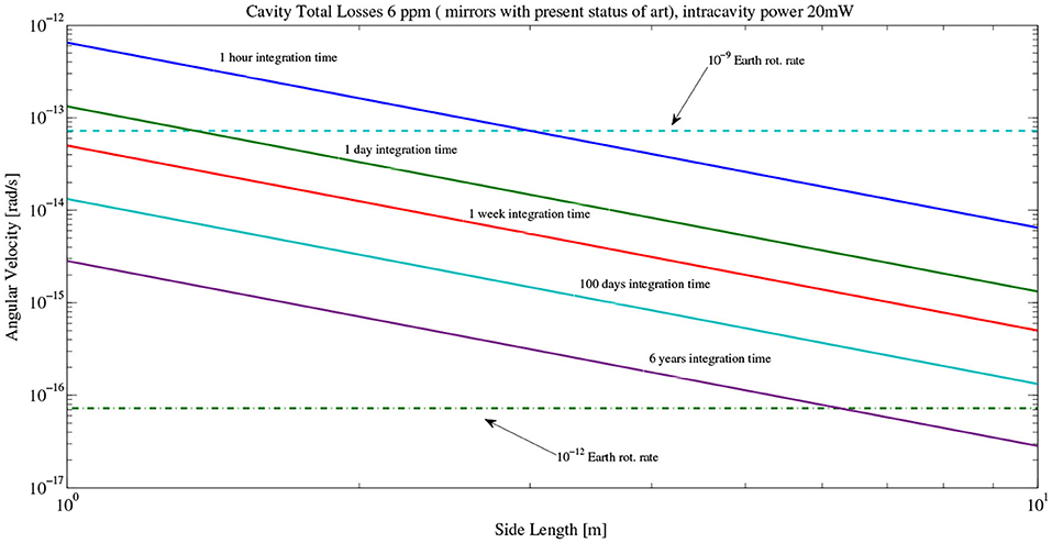
Figure 2. Sensitivity limit in function of the RLG side length, assuming 6 ppm total losses of the cavity (present best mirrors), internal power 70 mW (output power 20 nW, mirror transmission 0.3 ppm). The two GINGER targets, expressed as fraction of Earth rotation rate, are over-imposed.
Figure 2 shows the expected sensitivity, starting from the state-of-the-art (mirrors produced by FIVE9) of 10 prad/sHz−1/2, with μ = 44 ppm, assuming a reduction of the losses per mirror down to 6 ppm.
5.1. Resolution for Angular Rotation Rate and Angle Changes
RLGs are shot-noise limited sensors. In this section, the sensitivity limit induced by the shot noise will be discussed in function of the angle ζ, assuming the device ideal, i.e., comparing the variations of Equation (2) with the sensitivity limits induced by the shot noise. The measured quantity is fs, the Sagnac frequency, and it is therefore necessary to express the frequency variation δfs of fs due to shot noise:
Equation (2) shows that changes in scale factor (i), in orientation, i.e., δζ, and angular rotation rate changes δω will affect the response of the instrument. Since our gyros are fixed to the ground, all those changes are small, and can be studied with a first order expansion. The scale factor is a proportionality coefficient, should be stabilized by means of electronic control, and will be discussed in the scale factor control; here, the sensitivity for angular rotation rate and the inclination angle will be evaluated and discussed assuming that the inclination angle is ζ + δζ and the angular velocity Ω + δΩ. Equating the variations with shot noise the following limits are found:
The final sensitivity depends to the second power of the side length of the square device and on the static angle ζ, the orientation of the RLG with respect to the angular rotation rate direction. Regarding δΩ it is straightforward to see that angle ζ±π must be avoided, while δζ cannot be evaluated when the area versor is co-aligned with the velocity direction ±π. An angle of ±π/2 must thus be avoided for measurement of Ω, and when it is co-aligned, at the maximum Sagnac signal, it measures the modulus of Ω but is not sensitive to the variations of the inclination angle δζ. With the choice , Pin = 70 mW, static inclination angle of 45° we obtain the sensitivity rad/s, and rad for the angular rotation and the angle, respectively. The sensitivity of the RLG at ζ = 0 is slightly better rad/s. Assuming the integration time T = 3, 600 s, it is possible to show that the RLG must have side length l > 3.5 m in order to fulfill the above listed requirements, and l > 6 m will provide a shot noise a factor three below the target.
In general, a single RLG response will change the angular rotation rate or the relative alignment, and it is impossible to discriminate between δΩ or δζ; the RLG is aligned at the maximum Sagnac signal, and it provides the modulus of Ω and the variations of δΩ, while it is fairly insensitive to δζ, which affects to second power. Each RLG cannot be oriented with θ = ±π/2 since in this case the error would be too high. When it is aligned with the direction of Ω, the device is insensitive to δζ, called RLG at maximum Sagnac signal, and it is the best solution to deliver the modulus of Ω, and the error is also minimal.
6. Ring Lasers for Retrieving a General Rotation Vector and Evaluation of ζ
The beat frequency f of the RLG is proportional to the flux of the total rotation vector across the area of the ring. In general, we may write:
where is the unit vector perpendicular to the plane of the ring, is the scale factor of the RLG, and A and P are the area and perimeter of the ring cavity.
Taking into account the fact that Ω⊕ and the GR terms are contained inside the meridian plane, it is possible to restrict the analysis to the case of only two RLGs, arranged in such a way that these versors and the are all contained in one plane, and the problem becomes bi-dimensional. Calling the two, RL2 and RL1, making the scalar products explicit, we may write:
As shown in Figure 1 the area versors of the two RLGs are and , ζ is the angle between and , and γ is the angle between and , which can be independently measured. The two indices can be interchanged. Using Equation (12) the quantities Ω (the magnitude of ), and ζ can be retrieved:
or equivalently as . Each scale factor depends on the geometry of the RLG; devices with equal scale factors (S2 = S1 = S) are feasible to a certain extent, and the equations simplify if the RLG have equal scale factors (S2 = S1 = S):
The combination of the frequencies of the two RLGs determines the measurement of the amplitude of Ω, and, if the angle γ between the two RLs is independently measured, it is possible to measure ζ, the angle between the versor and the axis of the vector (γ − ζ being the angle between and , which in the following will be called ζ1).
It is extremely important that in this two-RLG system it is possible to determine the angle ζ of one of the two RLGs with respect to . It is necessary to estimate the error in the measurement of ζ, which depends on the independent measurement of γ and the indetermination of the frequencies, i.e., the shot noise. The error δζγ of ζ is proportional to the error δγ of the measurement of γ:
In general, the term multiplying δγ on the RHS of Equation (15) is not small, and the error in the measured ζ depends on δγ, i.e., the error in the measurement of the relative angle between RL1 and RL2.
Other noises will affect the evaluation of ζ. The output frequencies of the RLGs are shot-noise limited, and, assuming that the different contributions are independent, we therefore have
where δfsn is the shot noise, expressed in frequency. This noise contribution will be equal for both RLGs since they are considered equal in geometry, power, mirrors, etc.
Let us consider the special case in which RL1 is closely aligned with the total axis of rotation (). In this case, the angle ζ1 ≪ 1, assuming that γ is known with the error δγ (ζ1 = γ + δγ − ζ), substituting in Equation (12), it is possible to show that the error δζ depends at first order on the product ζ1 · δγ:
Assuming that cot ζ ≤ 2 (20° ≤ ζ ≥ 140°), it is straightforward to note that the error is depressed by the value of ζ1: improving the alignment of RL1 with the axis of rotation, the error δζγ decreases. For example, assuming rad, and δγ ~ 10−6 rad, we have δζγ ~ 10−12 rad. For example, if the RL2 is horizontally aligned with precision of 10−6 rad with respect to the local vertical, and rad, it is possible to say that the angle γ is equal to the co-latitude with an error δγ ≃ 10−6 rad, and it is not necessary to directly measure the angle γ.
Since a lot of disturbances will affect the apparatus, the orientation of the RL2 will change with time, and ζ will change accordingly (i.e., RL2 is a reference system not stable with respect to the local reference), it is impossible to distinguish between changes in the orientation of the RL2, or changes of , but the relative angle is always determined. The absolute orientation of RL1 does not play a significant role as long has ζ1 is sufficiently small; in the discussion of the experimental specifications the maximum allowed ζ1 will be evaluated.
The combination of two RLGs with one at maximum signal is very meaningful, as it allows very high precision in the determination of the angle ζ and the measurement of Ω (see Equation 12).
6.1. Array of RLGs in Order to Evaluate δω and δζ
As clearly said before the variation of the Sagnac frequency δfs of a single RLG can be interpreted as δΩ or as δζ, in order to discriminate the two, it is necessary to combine together more RLGs differently oriented, and, as we deal with vectors, three components are required in principle. So far, the response of each RLG in function of the orientation has been shown expressing the final sensitivity as shot noise is limited. The general response is that the discrimination is possible provide the relative angles γ1,2,3 are independently measured with adequate accuracy δγ1,2,3; in this way, enough equations can be written and solved (Tartaglia et al., 2017). In order to be shot-noise limited, the different δγ1,2,3 have to be at least compatible if not lower than the shot noise limits for δΩ and δζ, bearing in mind that no one of the RLG of the array has one of the not suitable orientations between the area. In order to evaluate δζ, at least two RLGs are necessary (since the Earth rotation axis is in the meridian plane, so the two RLG should have versors contained in the meridian plane), and the relative angle γ between the two RLGs should be independently measured with an error smaller than the shot noise limit of δζ. For instance, the sensitivity for the angle measurements should have an amplitude spectral density lower than the shot noise one 7.7 · 10−7/l2rad/s/; this is a rather tall order, and the larger the RLGs the higher is the required accuracy. In few words, for 6 m side rings, the required accuracy should be below 20 nrad in 1 s, and to that it is necessary to add the necessary continuous operation since it is possible that the angles may slightly change with time at the level of tens of nrad. Despite that, it must be said that suitable optical metrological systems exist (Donazzan et al., 2016) that have adequate accuracy; the problem is the cost and the fact that those systems measures distances between reference points, not between the light spots on the mirrors. A suitable solution exists that even avoids any external meterological system (Di Virgilio et al., 2017) with ad-hoc relative alignment of the rings: the RLG number 1 is aligned at the maximum Sagnac signal, and within an angular error that depends on the sensitivity required, this first ring will provide the modulus of Ω. The second ring could be horizontal, and in this way they will have both the area versor inside the meridian plane. The third could be vertical but not orthogonal or parallel to the meridian plane. Other solutions could be found for this third ring based on the available space and its orientation with the North6. Figure 3 shows a pictorial view of GINGER.
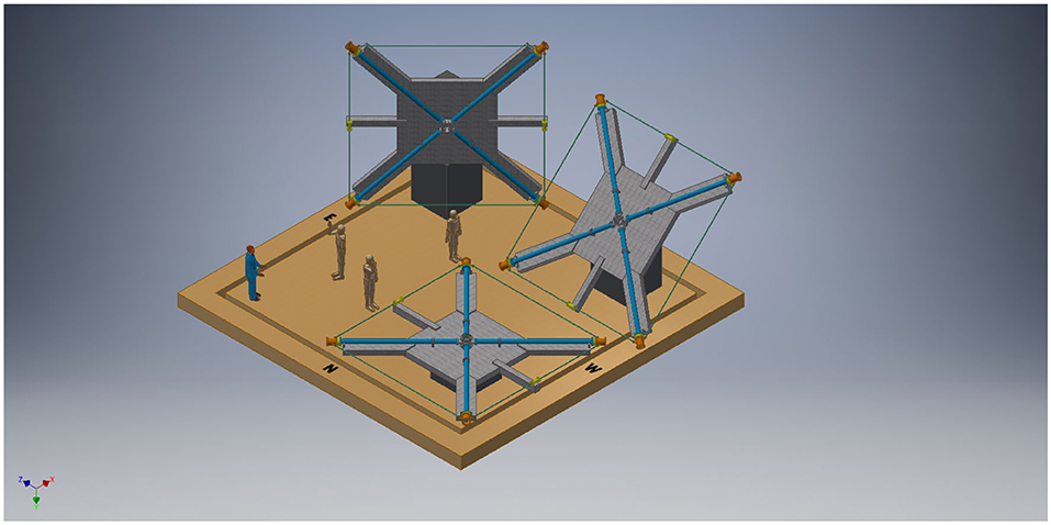
Figure 3. Pictorial view of GINGER, the three RLG are separated one from the other, and the details of the mechanical arrangement are shown.
As already said, the RLG 1 at the maximum Sagnac signal, i.e., parallel to the poles, has to be parallel to the poles with a certain error and has, in principle, adequate accuracy; for example, the proposed target could be obtained aligning the RLG at the maximum signal with mrad precision Di Virgilio et al. (2017). The second ring will provide changes of ζ in the meridian plane, while the third the projection of the changes in the plane defined by the two area versors of the first and third RLG.
Our prototype in Pisa, called GP2, is an example of a RLG aligned at the maximum signal; it is fixed, and so its alignment has not been optimized, but this is certainly feasible with “ad hoc” design of the mechanical HL RLG, equipped with actuators to optimize the alignment (Figure 4).
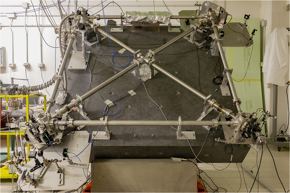
Figure 4. The RLG prototype GP2, oriented at the maximum Sagnac signal and devoted to tests of the geometry control.
6.2. Scale Factor Control
As already said the scale factor control is one of the requirements for high-sensitivity RLGs. Quite often, the control is simply done by controlling the perimeter in order to keep constant the wavelength. In short, a signal proportional to the wavelength can be obtained comparing one of the light modes with a reference laser source or also by observing the beat note between the higher-order modes resonating (in the same direction) inside the laser cavity, which is called auto-referencing. These methods, particularly the auto-referenced one, assume that the signal estimated with the wavelength depends on the geometry and the rotational signals only, while this should be avoided if noise of any nature affects the wavelength. To control the geometry, avoiding the RLG signals is feasible, and a simple procedure has been developed for GINGER. The control procedure will work in two steps. In the first step, the two diagonals are carefully measured and compared. Since the ring laser emission frequency is related to the ring perimeter length, it is possible to implement a procedure to optimize the geometry of the ring optical path by acting on the corner mirrors, as theoretically described in Santagata et al. (2015). It is possible to obtain a path which is as close as possible to a square by measuring the laser frequency at the same time with the diagonal lengths. In the second step, during the GINGER operation, the optical path geometry will be actively stabilized by locking the diagonal lengths to an external reference wavelength standard and will also act on the corner mirrors. From an experimental point of view, the diagonal lengths can be easily optically exploited, as they constitute two Fabry-Perot cavities, so that standard metrological techniques can be used. In these conditions, according to our analysis, a long-term stability of the scale factor of the order of 10−12 can be obtained if the error in the positions of the mirrors with respect to the square perfect geometry is lower than 1 μm (Santagata et al., 2015). This is the required stability for the 1% test of the Lense-Thirring effect (Di Virgilio et al., 2017). The GP2 prototype has been installed in a laboratory of the basement of the INFN Pisa building with the purpose of studying the experimental details of these procedures, and the main parts of the above explained procedure have already been tested (Beverini et al., 2020).
7. The Main Results of GINGERINO
In this section the main results of the large frame RLGs will be reported. It is a well-known fact that the G ring (monolithic RLG) of the geodetic observatory of Wettzell is the most sensitive one, and it has already proved the relative sensitivity of 1 part 3 · 109 of Ω⊕. The planned RLGS array, as ROMY (Schreiber et al., 2018), is based on the HL RLG mechanical scheme, and it is important to discuss the results of GINGERINO (square ring 3.6 m in side), which is an HL device operative on a continuous basis and of a similar shape to G (4 m in side) (see Figure 5). GINGERINO is based on a simple mechanical structure (made of steel), but it takes advantage of an underground quiet and thermally stable environment since it is located inside the Gran Sasso laboratory. Typically, the thermal stability is of the order of a few hundredths of a degree. GINGERINO is operative on a continuous basis unattended and free running with 95% duty cycle and sensitivity better than fractions of nrad/s in 1 s measurement. It has been the first HL operative with high duty cycle and sensitivity (Belfi et al., 2018). Since the geometry control has not been implemented, mode jumps and split mode operations do occur7, but typically they affects <5% of the data (Belfi et al., 2017, 2018). Our most recent study has shown that the main limitations are due to the systematic of the laser (Beghi et al., 2012; Cuccato et al., 2014; Di Virgilio et al., 2019), and we have developed a new analysis approach accordingly in order to improve the sensitivity. As already said, the measurement is based on the evaluation of the Sagnac frequency ωs from the measured beat note ωm of the two counterpropagating laser beams and the mono-beams signals PH1,2.
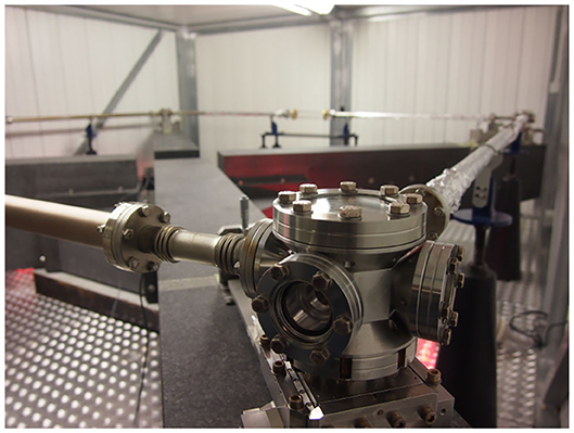
Figure 5. GINGERINO at the time of assembling. The mirror box and the pipes connecting the boxes, one of the Mitutoyo screw to orientate the mirrors is visible in front of the box. The mechanical structure is in steel, and the whole is attached to the granite monument, cross shaped, which provides stability of the ring perimeter.
7.1. The Analysis Scheme to Take Into Account Laser Dynamic
The general aim of the research is to evaluate the Sagnac frequency, eliminating the systematic due to the laser non-linear dynamic and using the available data: the measured beat note and the monobeams signals (Di Virgilio et al., 2019, 2020b). In the following, the Sagnac frequency will be express as a pulse frequency ωs (fs = ωs/2/π). This may generate confusion, but it is the preferable solution for the calculation which takes into account the laser dynamic. In our analysis, the true Sagnac signal ωs can be evaluated as the linear sum of several terms:
ωs0 contains most of the signal and takes into account the back-scatter term. In order to better define ωs0 and take into account the dark currents in the photodiode signals, the term ξ · ωsξ has been introduced. ξ is a proportionality constant that has to be evaluated by statistical means. These two terms are perfectly defined by the available measurements, and they do not depend on the laser dynamic:
where ωm is the measured beat note (expressed as pulse frequency), and I1,2, Is1, s2, and ϵ are respectively the DC level of the mono-mean signals, the amplitude at the beat note frequency, and the relative phase between the two beams.
The other terms in Equation (21) are rather small and can be evaluated by the available signals, but they require the evaluation of the Lamb coefficients (Menegozzi and Lamb, 1973)8 and the knowledge of the losses of the cavity μ. This quantity can be determined by the ring down time of the cavity with typically 10% error, but it can also display changes with time. As far as GINGERINO is concerned, it has been evident that μ changes with time, probably because the gain tube of the laser is not well-fixed, and its tiny motion modulates the losses of the optical ring cavity.
The general aim of the analysis will be to reconstruct ωs without any adjustment or fit, but since we are in a development phase and it is necessary to deeply investigate the quality and limits of the instrumentation, the present analysis is trying the recover ωs with statistical means. This is feasible since the dependence of the term , where μ is the total losses, considered unknown, while can be evaluated with the available measurements. In summary, the different terms are evaluated and stored on disk, and, in the second level of the analysis, the ξ and μ coefficients are found with linear regression models. It is important to remember that the available signals from the RLG are acquired at high frequency (typically 5 kHz), and the whole calculations have to be done at high frequency, in our case 2.5 kHz, and the data stored after decimation, usually 2, 1, or 0.1 Hz. The diagram in Figure 6 shows the first level, while Figure 7 shows the second analysis level. In Figure 8, we show on the left ωs0 and on the right the improvement after the subtraction with linear regression methods of ωsξ and ωns. In order to evaluate the influence of the environmental data on the apparatus, pressure, temperature, and other environmental monitors can be added to the linear regression model (Di Virgilio et al., 2019) (see Figure 7), assuming that they have a linear relationship with ωs0, which is certainly a good approximation for very small variations.
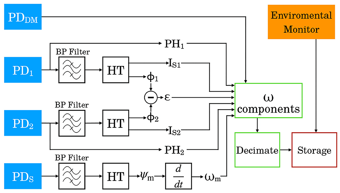
Figure 6. First analysis level and data storage.
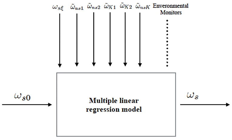
Figure 7. Linear regression model analysis scheme: with statistical means, the parameters ξ and μ, related to the reduction of the laser dynamic systematic, and all other parameters should take into account the environmental monitors are evaluated to determine ωs.
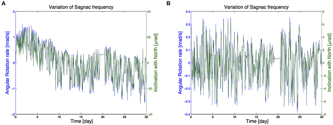
Figure 8. (A) The data utilized in the present analysis (30 days from June 15, 2018), ωs0 with mean subtracted, and the data after around day 20 have been removed since GINGERINO was in split mode. (B) ωs, mean subtracted, evaluated with the model of the laser systematic. The data have been decimated down to 1,800 s. Since GINGERINO is a single-ring gyroscope, with an ~45° inclination with the Earth axis, it is impossible to distinguish rotations and inclinations. On the right, the sensitivity is expressed in change of the relative angle with the Earth rotation axis, showing that the orientation of the apparatus of GINGERINO is stable at the level of a few μ rad.
7.2. Analysis Results
Several bunches of data are at present under investigation, and we briefly report here the evaluated ωs of 11 consecutive days starting from MJD 58007. Figure 9 shows the modified Allan deviation of the above data; with an integration time of 3 h, the MAD is 7 · 10−8, a figure a factor 70 far from the first target of GINGER. At present, we do not know the origin of the extra noise present in the region of several days, but we have checked that this level noise is a factor 2 − −3 larger than the polar motion signal (Di Virgilio et al., 2020a). It is important to remember that the geometry is not controlled, and the thermal expansion certainly plays a role. As far as we know, at present this is the best result for HL RLGs. This analysis has also shown that the orientation of the apparatus of GINGERINO is stable at the level of μrad, indicating that the Gram Sasso laboratory it a good location for the installation of a RLG at the maximum signal.
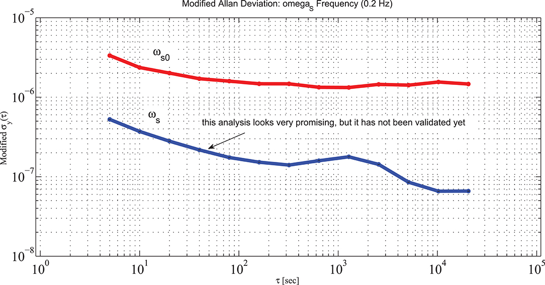
Figure 9. Modified Allan Deviation of the evaluated ωs0 and the ωs evaluated taking into account other terms induced by the laser dynamic; this analysis is still ongoing, and will be further investigated in the future.
8. Conclusions
The G ring of the geodetic observatory of Wettzell has demonstrated the feasibility of the measurement of the Earth rotation rate with relative precision of at least of 1 part in 3 · 109. G is based on a monolithic cavity, a scheme which cannot be further extended to develop an array of RLGs. The second generation of large frame RLGs are based on the so-called HL mechanical scheme, The HL RLG GINGERINO has already obtained 95% of duty cycle with high sensitivity (Belfi et al., 2018). It is a well-known fact that the dynamic of the laser is non-linear, and this fact so far has been a strong limitation for the diffusion of those instruments. At the end of 2018, we were able to find a suitable way to improve the analysis taking into account the laser dynamic. This analysis is still ongoing, the preliminary result shows that the response of GINGERINO is highly dominated by the laser dynamics. For example, the analysis of 11 days (September 2017) shows a Modified Allan Deviation going down to 7 · 10−8 after 3 h of integration, a value compatible with the thermal expansion of the geometry, with an improvement of more than a factor 10 with respect to the standard analysis approach.
GINGERINO has also shown that the Gran Sasso laboratory is stable in orientation at the level of a few μrad in the time lag of a few months, showing that it is a suitable location for the RLG at the maximum Sagnac signal. An RLG oriented at the maximum Sagnac signal would provide the modulus of the Earth angular rotation, and any other orientation would provide a projection of .
HL RLG are improving their sensitivity and the proposed target for application in geodesy of RLG seams now feasible.
Due to its very high sensitivity, GINGER, and any other similar RLG array, will provide at the same time suitable data for fundamental physics, geodesy and geophysics.
Data Availability Statement
The raw data supporting the conclusions of this article will be made available by the authors, without undue reservation upon reasonable request.
Author Contributions
The author confirms being the sole contributor of this work and has approved it for publication.
Funding
This research has been carried out and financed by the Italian INFN Research Institute.
Conflict of Interest
The author declares that the research was conducted in the absence of any commercial or financial relationships that could be construed as a potential conflict of interest.
Acknowledgments
I must acknowledge the work and the fruitful discussion I have had with all the physicists that have taken part in the RLG work around our ring laser prototypes. In particular, I have to mention Nicolò Beverini, Angelo Tartaglia, Jacopo Belfi, Enrico Maccioni, Antonello Ortolan, and Alberto Porzio.
Footnotes
1. ^Ultra-low expansion material: we note that very small RLGs for navigation have a similar monolithic design.
2. ^In the HL RLG, the mirrors are contained in small vacuum boxes in steel and connected together by tubes in order to enclose the whole light path in the same vacuum tank; the whole is supported by a rigid frame in reinforced concrete or granite. The mirrors are equipped with actuators and can be moved to optimize the relative alignment. In this case, the scale factor has to be electronically controlled.
3. ^This discussion is done using RLGs, but it is general and can be applied to any array based on Sagnac gyroscopes.
4. ^η⊥ and η∥ are the projections of , the vector we are going to evaluate, and are perpendicular and parallel, respectively, to .
5. ^For instance, this implies that losses associated with the gain tube must be minimized.
6. ^It is important to remind that we are talking to RLG attached to the Earth crust, which basically are going to study the Earth rotation rate Ω⊕ changes in amplitude and absolute orientation.
7. ^When the geometry changes, the wavelengths of the two modes changes accordingly. The mode jump is when they jump together while the split mode is when the difference between the two modes is separated by one free spectral range of the cavity. The mode jump affects a very small portion of data, typically a few seconds, while the split mode operation affects several hours, and split modes of several hours duration may occur.
8. ^All those calculations are feasible with the available data, but they require other information, such as beam size at the discharge, pressure of the gas, polarization of the gas, detailed characteristics of the gas, etc.
References
Beghi, A., Belfi, J., Beverini, N., Bouhadef, B., Cuccato, D., Virgilio, A. D., et al. (2012). Compensation of the laser parameter fluctuations in large ring-laser gyros: a Kalman filter approach. Appl. Opt. 51, 7518–7528. doi: 10.1364/AO.51.007518
Belfi, J., Beverini, N., Bosi, F., Carelli, G., Cuccato, D., De Luca, G., et al. (2017). Deep underground rotation measurements: Gingerino ring laser gyroscope in gran sasso. Rev. Sci. Instrum. 88:034502. doi: 10.1063/1.4977051
Belfi, J., Beverini, N., Carelli, G., Virgilio, A. D., Giacomelli, U., Maccioni, E., et al. (2018). Analysis of 90 day operation of the gingerino gyroscope. Appl. Opt. 57, 5844–5851. doi: 10.1364/AO.57.005844
Beverini, N., Carelli, G., Virgilio, A. D., Giacomelli, U., Maccioni, E., Stefani, F., et al. (2020). Length measurement and stabilisation of the diagonals of a square area laser gyroscope. Class. Quant. Grav. 37:065025. doi: 10.1088/1361-6382/ab4fd1
Bosi, F., Cella, G., Di Virgilio, A., Ortolan, A., Porzio, A., Solimeno, S., et al. (2011). Measuring gravitomagnetic effects by a multi-ring-laser gyroscope. Phys. Rev. D 84:122002. doi: 10.1103/PhysRevD.84.122002
Ciufolini, I., Paolozzi, A., Pavlis, E. C., Koenig, R., Ries, J., Gurzadyan, V., et al. (2016). A test of general relativity using the lares and lageos satellites and a grace earth gravity model–measurement of earth's dragging of inertial frames. Eur. Phys. J. C 76:120. doi: 10.1140/epjc/s10052-016-3961-8
Ciufolini, I., and Pavlis, E. C. (2004). A confirmation of the general relativistic prediction of the lense-thirring effect. Nature 431, 958–960. doi: 10.1038/nature03007
Cochard, A., Igel, H., Schuberth, B., Suryanto, W., Velikoseltsev, A., Schreiber, U., et al. (2006). “Rotational motions in seismology: theory, observation, simulation,” in Earthquake Source Asymmetry, Structural Media and Rotation Effects, eds R. Teisseyre, E. Majewski, and M. Takeo (New York, NY: Springer), 391–411. doi: 10.1007/3-540-31337-0_30
Cuccato, D., Beghi, A., Belfi, J., Beverini, N., Ortolan, A., and Virgilio, A. D. (2014). Controlling the nonlinear inter cavity dynamics of large he-ne laser gyroscopes. Metrologia 51, 97–107. doi: 10.1088/0026-1394/51/1/97
Di Virgilio, A. D. D., Giacomelli, U., Beverini, N., Carelli, G., Ciampini, D., Fuso, F., et al. (2020b). Identification and correction of sagnac frequency variations: an implementation for the gingerino data analysis. Eur. Phys. J. C 80:163. doi: 10.1140/epjc/s10052-020-7659-6
Di Virgilio, A. D. V., Basti, A., Beverini, N., Bosi, F., Carelli, G., and Ciampini, D. (2020a). Underground Sagnac gyroscope with sub-prad/s rotation rate sensitivity: toward general relativity tests on earth. Phys. Rev. Res. 2:032069. doi: 10.1103/PhysRevResearch.2.032069
Di Virgilio, A. D. V., Belfi, J., Ni, W.-T., Beverini, N., Carelli, G., Maccioni, E., et al. (2017). Ginger: a feasibility study. Eur. Phys. J. Plus 132:157. doi: 10.1140/epjp/i2017-11452-6
Di Virgilio, A. D. V., Beverini, N., Carelli, G., Ciampini, D., Fuso, F., and Maccioni, E. (2019). Analysis of ring laser gyroscopes including laser dynamics. Eur. Phys. J. C 79:573. doi: 10.1140/epjc/s10052-019-7089-5
Donazzan, A., Naletto, G., Pelizzo, M. G., Cuccato, D., Beghi, A., Ortolan, A., et al. (2016). “External metrology system for the stabilization of large ring-lasers,” in 2016 IEEE Metrology for Aerospace (Metroaerospace) (Florence: IEEE), 266–270. doi: 10.1109/MetroAeroSpace.2016.7573224
Everitt, C. W. F., DeBra, D. B., Parkinson, B. W., Turneaure, J. P., Conklin, J. W., Heifetz, M. I., et al. (2011). Gravity probe B: final results of a space experiment to test general relativity. Phys. Rev. Lett. 106:221101. doi: 10.1103/PhysRevLett.106.221101
Igel, H., Cochard, A., Wassermann, J., Flaws, A., Schreiber, U., Velikoseltsev, A., et al. (2007). Broad-band observations of earthquake-induced rotational ground motions. Geophys. J. Int. 168:182. doi: 10.1111/j.1365-246X.2006.03146.x
Liu, K., Zhang, F. L., Li, Z. Y., Feng, X. H., Li, K., Lu, Z. H., et al. (2019). Large-scale passive laser gyroscope for earth rotation sensing. Opt. Lett. 44, 2732–2735. doi: 10.1364/OL.44.002732
Lucchesi, D. M., Anselmo, L., Bassan, M., Magnafico, C., Pardini, C., Peron, R., et al. (2019). General relativity measurements in the field of earth with laser-ranged satellites: state of the art and perspectives. Universe 5:141. doi: 10.3390/universe5060141
Menegozzi, L. N., and Lamb, W. E. (1973). Theory of a ring laser. Phys. Rev. A 8:4. doi: 10.1103/PhysRevA.8.2103
Moseley, S., Scaramuzza, N., Tasson, J. D., and Trostel, M. L. (2019). Lorentz violation and sagnac gyroscopes. Phys. Rev. D 100:064031. doi: 10.1103/PhysRevD.100.064031
Nilsson, T., Böhm, J., Schuh, H., Schreiber, K. U., Gebauer, A., and Klügel, T. (2012). Combining VLBI and ring laser observations for determination of high frequency earth rotation variation. J. Geodyn. 62, 69–73. doi: 10.1016/j.jog.2012.02.002
Pascoli, G. (2017). The sagnac effect and its interpretation by Paul Langevin. Comptes Rendus Phys. 18, 563–569. doi: 10.1016/j.crhy.2017.10.010
Ruggiero, M. L., and Tartaglia, A. (2019). Test of gravitomagnetism with satellites around the earth. Eur. Phys. J. Plus 134:205. doi: 10.1140/epjp/i2019-12602-6
Sagnac, G. (1913a). The demonstration of the luminiferous aether by an interferometer in uniform rotation. Comptes Rendues 157:708–710.
Sagnac, G. (1913b). On the proof of the reality of the luminiferous aether by the experiment with a rotating interferometer. Comptes Rendues 157, 1410–1413.
Santagata, R., Beghi, A., Belfi, J., Beverini, N., Cuccato, D., Virgilio, A. D., et al. (2015). Optimization of the geometrical stability in square ring laser gyroscopes. Classic. Quant. Grav. 32:055013. doi: 10.1088/0264-9381/32/5/055013
Schreiber, K., Klügel, T., Wells, J.-P. R., Hurst, R., and Gebauer, A. (2011). How to detect the Chandler and the annual wobble of the earth with a large ring laser gyroscope. Phys. Rev. Lett. 107:173904. doi: 10.1103/PhysRevLett.107.173904
Schreiber, K. U., and Wells, J.-P. R. (2013). Invited review article: large ring lasers for rotation sensing. Rev. Sci. Instrum. 84:041101. doi: 10.1063/1.4798216
Schreiber, U., Igel, H., Wassermann, J., Simonelli, A., Gebauer, A., Kodet, J., et al. (2018). Progress in Sagnac Interferometry. Wettzell: European Geosciences Union General Assembly.
Scully, M. O., Zubairy, M. S., and Haugan, M. P. (1981). Proposed optical test of metric gravitation theories. Phys. Rev. A 24, 2009–2016. doi: 10.1103/PhysRevA.24.2009
Simonelli, A., Igel, H., Wassermann, J., Belfi, J., Di Virgilio, A., Beverini, N., et al. (2018). Rotational motions from the 2016, central Italy seismic sequence, as observed by an underground ring laser gyroscope. Geophys. J. Int. 214, 705–715. doi: 10.1093/gji/ggy186
Spallicci, A., Brillet, A., Busca, G., Catastini, G., Pinto, I., Roxburgh, I., et al. (1997). Experiments on fundamental physics on the space station. Classic. Quant. Grav. 14, 2971–2989. doi: 10.1088/0264-9381/14/11/003
Takeo, M., and Ito, H. M. (1997). What can be learned from rotational motions excited by earthquakes? Geophys. J. Int. 129:319. doi: 10.1111/j.1365-246X.1997.tb01585.x
Tartaglia, A. (2018). Dark angular momentum of the galaxy. Int. J. Mod. Phys. D 27, 1847012–1847011. doi: 10.1142/S0218271818470120
Tartaglia, A. (2019). Detecting the angular momentum of the galactic dark halo. Adv. Space Res. 64:545. doi: 10.1016/j.asr.2019.04.031
Tartaglia, A., Di Virgilio, A., Belfi, J., Beverini, N., and Ruggiero, M. L. (2017). Testing general relativity by means of ring lasers. Eur. Phys. J. Plus 132:73. doi: 10.1140/epjp/i2017-11372-5
Keywords: gyroscopes, laser, earth rotation change, lense-thirring effect, seismology
Citation: Di Virgilio ADV (2020) Sagnac Gyroscopes and the GINGER Project. Front. Astron. Space Sci. 7:49. doi: 10.3389/fspas.2020.00049
Received: 28 September 2019; Accepted: 30 June 2020;
Published: 06 October 2020.
Edited by:
Roberto Peron, Institute for Space Astrophysics and Planetology (INAF), ItalyReviewed by:
Alessandro D. A. M. Spallicci Di Filottrano, Université d'Orléans, FranceAnna M. Nobili, University of Pisa, Italy
Copyright © 2020 Di Virgilio. This is an open-access article distributed under the terms of the Creative Commons Attribution License (CC BY). The use, distribution or reproduction in other forums is permitted, provided the original author(s) and the copyright owner(s) are credited and that the original publication in this journal is cited, in accordance with accepted academic practice. No use, distribution or reproduction is permitted which does not comply with these terms.
*Correspondence: Angela D. V. Di Virgilio, YW5nZWxhLmRpdmlyZ2lsaW9AcGkuaW5mbi5pdA==