 Chinmayee Govinda Raj1
 Michael Cato2Nicholas Colby Speller2Zachary Duca3Philip Putman4Jason Epperson4Shaun Foreman5
 Jungkyu Kim6Amanda Stockton1*
- 1School of Chemistry and Biochemistry, Georgia Institute of Technology, Atlanta, GA, United States
- 2Georgia Tech Research Institute, Atlanta, GA, United States
- 3Savannah River National Laboratory, Jackson, SC, United States
- 4Sierra Lobo, Inc., Milan, OH, United States
- 5Department of Mechanical Engineering, Texas Tech University, Lubbock, TX, United States
- 6Department of Mechanical Engineering, University of Utah, Salt Lake City, UT, United States
Europa is an established high-priority astrobiology target where identifying chemical signatures of life is one of NASA’s highest-priority goals. Remote sensing techniques are powerful tools for extraterrestrial exploration, but in situ data through analyses of subsurface materials is necessary for ground-truthing these habitability investigations. Instrument designs fitting small volume, mass, and power consumption envelopes have a high potential for enabling efficient, low-cost missions. The Ice Shell Impact Penetrator (IceShIP) is a state-of-the-art miniaturized payload design dedicated to lower-cost extraterrestrial impact-penetrator missions. It houses the Icy Moon Penetrator Organic Analyzer (IMPOA), a first-of-its-kind payload housing miniaturized analytical instrumentation employing laser-induced fluorescence for the detection of low concentration organic species pervasive in the solar system. IMPOA is capable of sustaining high g-loads, avoiding the need for soft landing platforms, and facilitating crustal penetration for subsurface sample analyses. Three IMPOA test articles with varying material choices, construction designs, and internal components were modeled using COMSOL Multiphysics and then tested at 12 k-g, 25 k-g, and 50 k-g accelerations in an air gun assembly. The internal components consisted of linear piezoelectric micro-actuators, microcontroller board, mock microfluidic glass wafers, collimating lens, optical filters, and laser diodes. This work focuses on an extensive analysis of the impact-tested components. All components physically survived the impact tests except the mock microfluidic disk. Functionality tests of the individual components confirm their survival post-impact. All components used in this design are commercially available or easily machinable, which will simplify technology transfer for further technology elevation. Impact-resistance, miniaturization, energy efficiency, and cost-effectiveness are pivotal for impact-penetrator space-flight missions. This work satisfies these key aspects and demonstrates technology of a novel design for astrobiological in situ instrumentation.
Introduction
Europa, the smallest of the four Galilean moons, is an established target for astrobiological exploration due to its potential for habitability (National Research Council, Division on Engineering and Physical Sciences Space Studies Board, 2012). Scientific investigations to comprehensively test for habitability require access to subsurface materials (Hand, 2017). The Europa Lander is a concept flagship mission that could be the first in situ lander mission to look for signs of life in the icy crust of Europa (Hand, 2017). Typically, in situ missions are heavy and power-hungry with fragile instruments requiring complex soft lander deployment platforms that demand significant time and resource allocation for their development, launch, and operation. After landing, the Europa Lander would require robotic ice-drilling equipment for accessing radiation-shielded samples from beneath the surface. It would also be stationary, failing to provide geochemical spatial distribution information; Europa’s chaotic and diverse terrain, and the current lack of high-resolution surface maps, raise the likelihood of mission failure.
As an alternative to soft landers, low-cost impactor missions have been used for proxy in situ analyses, where a heavy impactor body strikes the surface and the debris ejected by impact is observed with a remote, often spacecraft-based, suite. An example is the Lunar Crater Observation and Sensing Satellite (LCROSS) mission, which had a 2,000 kg impactor to strike and loft subsurface material into the sunlight to be detected by Earth-based telescopes (Strycker et al., 2013). Another example is the Hayabusa2 mission, which had a 14 kg impactor to eject a sample from asteroid Ryugu (Saiki et al., 2013) that was then collected and sent back to Earth for further analysis (Saiki et al., 2017). In some cases, the impactor bodies carry instruments designed to function until the impact event, with examples being the Ranger series missions, Deep Impact, and Chandrayan-I. The Ranger series missions carried cameras to obtain close-up images of the Moon’s regolith (Hall, 1977), the Deep Impact mission to comet Tempel 1 (Meech et al., 2000) had fully functional self-navigation devices for flight path correction (Blume, 2003), and more recently, Chandrayaan-1’s Moon Impact Probe (MIP) had altimeters and CCD cameras. All of these probes transmitted back data until they crashed into the surface as planned. (Imbriale, 2006; Sridharan et al., 2010; Corda, 2017). Although successful by intended design, these probes fail to provide geochemical spatial distribution information, and could not collect in situ astrobiological measurement after impact.
In order to carry out true in situ analyses of subsurface material, penetrator mission architectures are important. Penetrators are designed to survive high-g impact loads, penetrating the crust to some depth, then conduction of on-board analyses. The letter g corresponds to the acceleration due to gravity on Earth, which is 9.8 m/s. The Lunar penetrometer is one example, which carried an omnidirectional accelerometer (McCarty et al., 1964; Carden and Mc Carty, 1968) to assess the penetrability and load-bearing characteristics of the Moon’s surface by measuring the acceleration profile during impact (Scientific and Technical Aerospace Reports, 1966). Sixteen penetrometers underwent freefall direct deployment and sent back data, making it the first and only successful penetrator mission to date (McCarty and Carden, 1967). The next penetrator mission three decades later, Mars-96 included a camera, thermoprobe detectors, and a magnetometer; inside, it housed a seismometer and spectrometers (Surkov and Kremnev, 1998), but failed during launch (Surkov and Kremnev, 1998; Lorenz, 2011). The Deep Space 2 mission to the Martian north pole was designed to sustain 30 k-g impact force and achieve a penetration depth of 0.2–0.6 m in pursuit of electrochemical data (Smrekar et al., 1999), but all communication was lost after impact (Albee et al., 2000; Lorenz, 2011).
Despite the relatively few examples of instrumented penetrator missions, interest in the concept remains high due to their potential for low-cost, high quality science data return. A joint penetrator was being designed for icy moons with velocities in the 100–300 m/s range to achieve a depth of 20–100 cm, with recommended penetrator components including power, communications, thermal control system, and supporting electronics for a seismometer (Gowen et al., 2011). Penetrators capable of surviving impact velocities in the 300–600 m/s range have been demonstrated to penetrate 1–2 m and collect terrestrial geologic cores (Winglee et al., 2017). Hopf et al. (2010) have reported on shock protection using encapsulants for seismometers for Europa and have demonstrated survival under loads of up to 15 k-g. Though the need for analytical instruments on penetrators for astrobiology-related science return is acknowledged as a critical need, they are currently not devoted to including them in their designs to date. No chemical analysis instrumentation has been built and tested at high-g loads for use with penetrators.
Analytical devices that can detect and identify amino acids are essential on astrobiology-oriented instrument suites (Neveu et al., 2018). Amino acids are recognized indicators for understanding a planetary body’s geochemistry based on their abundance distributions and the chemical processes that govern their production (Neveu et al., 2018). Amino acid chirality and compositional information is also thought to be a potential biomarker (Neveu et al., 2018; Duca et al., 2020). Amino acids are found in low abundances in multiple extraterrestrial samples (Ehrenfreund et al., 2001; Pizzarello, 2006) and require extremely sensitive detection techniques in situ. Laser-induced fluorescence (LIF) is a well-established, ultrasensitive, non-destructive technique requiring easily accessible commercial off-the-shelf (COTS) elements for the detection of these low concentration organic species. LIF on a microfluidic platform has the potential to meet challenging requirements of planetary missions by fitting within small volume, mass, power envelope designs, and promising rapid analyses with small sample volume consumption (Duca et al., 2022).
In this work, we discuss the construction of a compact instrument for a penetrator module capable of achieving a depth of 1–10 m. The Ice Shell Impact Penetrator (IceShIP) is a state-of-the-art payload design dedicated to extraterrestrial impact-penetrator missions. It contains the Icy Moon Penetrator Organic Analyzer (IMPOA), a first-of-its-kind miniaturized analytical instrument employing LIF for the detection of low concentration organic species necessary for the origin of life and habitability (Ehrenfreund et al., 2001; Pizzarello, 2006; Higgs and Pudritz, 2009). Three test articles with different body materials, construction designs, and internal components were modeled and tested experimentally at three accelerations using an air gun-magnetic capture assembly. This work focuses on an extensive analysis of the disassembled, impact-tested components. Canister geometries, component positional alignments, and electro-optical parameters of the lenstube assembly elements have been examined. All components used in this design are commercially available, simplifying technology transfer for further TRL elevation. Multiple IceShIP payloads could ride on a Discovery-class orbiter mission and be deployed at various locations to collect samples with significant geographical spacing without roving capabilities. Impact-resistance, miniaturization, energy efficiency, and cost-effectiveness are pivotal for impact-penetrator space-flight missions. This work satisfies these key aspects and demonstrates technology for a novel design for astrobiological in situ instrumentation.
Concept
The mission concept is shown in Figure 1. Instrumentation is housed in an impact-robust sabot, and the impact force could facilitate penetration into the ice crust (Figure 1A) with depths dependent on surface properties and sabot mass and geometry. Sample could be internalized during impact, and heaters on the sabot could enable melt flow for sampling (Figure 1B), with sipper ports placed nearby to intake liquid samples and deliver to the integrated microfluidic device (Figure 1C). An on-chip pumping mechanism could transfer the sample through the microfluidic device, facilitating mixing with a dye for laser-induced fluorescence (LIF) detection (Figure 1D).
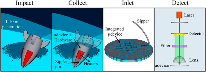
FIGURE 1. Artist’s representation of the sequence of operations of an IMPOA payload for detection of organics after “impact”, sample “collection”, “sample inlet” into the microfluidic device, followed by “detection”.
The LIF stack used for detection could be a single-axis design as opposed to the traditional orthogonal axis setup to improve impact resistance and miniaturization. Laser source emission would pass through a pinhole, focused by a half-ball lens to a spot in the microfluidic channel. Fluorescent light emission would be collected, collimated, passed through an optical filter, and collected by a custom patterned or commercial off-the-shelf photodetector (Duca et al., 2022). A cluster of IceShIP canisters, each with a starting payload chassis mass of 1 kg, could ride on a single Discovery-class orbiter and could be ejected at different time intervals to achieve significant geographical distribution without the need for a soft landing or ground roving capabilities.
Materials and Methods
Three test article canisters were machined in aluminum and stainless-steel alloys specific for each impact test. Machining was carried out at the Mechanical Engineering and Biomedical Engineering machine shops at the Georgia Institute of Technology (Atlanta, GA, United States). All stock metal and hardware materials were purchased from McMaster-Carr (Elmhurst, IL, United States) unless noted otherwise. The CAD designs of all test articles are shown in Supplementary Figures SA–SD. All x-ray analyses were carried out at the GA Tech Material Characterization Facility using the Dage x-ray system (XD7600NT, Nordson, Westlake, OH, United States). The COTS components used are tabulated in Supplementary Table SA. More information on test article assembly can be found in Cato et al. (2022).
Impact Test Assembly Specifications
Impact testing was performed utilizing a pressurized air gun with the M100 magnetic capture system at a Sierra Lobo test facility in Milan, OH, United States. The M100 allowed repeatable, non-destructive, high-g testing by creating an induced magnetic field with enough power to serve as an electromagnetic brake. The first test article inside the carrier is shown in Figures 2A,B. The articles were machined to snugly fit inside the carrier (PN: RD14-6011, Sierra Lobo, Milan, OH, United States), which was made to keep the test article centered in the magnetic capture system, and stiff spacers were used around the article to stabilize and avoid damping the loads experienced by the test articles inside. To meet the needs of rapid turnaround time and test requirement flexibility, key components in the system were fabricated using additive manufacturing methods. Impact tests #2 and #3 had an updated, consumable carrier printed out of white polycarbonate (Figure 2C) using a 3D-printer (MK2, Prusa Research, Czech Republic). A thin plastic liner tube (Proto Labs, Maple Plain, MN, United States, and ShapeWays, New York, NY, United States) was placed inside the capture system’s catch tube to provide a smooth pathway for the projectile and to protect the tube and magnets from the test article and debris.
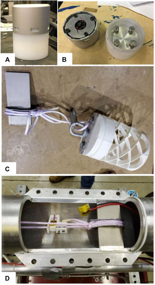
FIGURE 2. Impact test assembly. (A,B) Test article #1 inside the carrier. (C) 3D-printed polycarbonate carrier used with tether for test articles #2 and #3. (D) Tether and thermal knife system.
To get consistent release conditions with each test, a tether (SKU: NE133D, Teufelberger, Austria) and thermal knife system (PN: RD14-6012, Sierra Lobo, Milan, OH, United States) (Figure 2D) was used. The tether held the test article in place while the air gun ramped to the typical 100 PSIG test pressure. The knife was remotely activated to cut through the tether during testing. Two measurements were used to obtain the acceleration -- piezoelectric accelerometers (PN: 352C04, PCB Piezoelectronics, Depew, NY, United States) mounted on the capture skid, and a high-speed video camera (v210, Phantom, Wayne, NJ, United States) to record the slug as it stopped through a slot in the capture tube. Stopping distance was measured on the system sled. The data from the camera was used to obtain another measurement of the stopping distance, a position curve and velocity. The camera could directly track the test article as it stopped through a slot in the liner. Video and image processing was performed on Mathematica (Wolfram, Champaign, IL, United States) and Tracker (Open Source Physics) to find the position function, derivatives of which result in velocity and acceleration, giving the best plots for the acceleration. The resulting acceleration plots from the camera agreed with the average acceleration calculated from the stopping distance.
Computational Modeling
COMSOL Multiphysics (Stockholm, Sweden) software equipped with the structural mechanics module was used for impact simulations. A pulse wave spanning 1 ms was applied to visualize the effects of 12 k-g, 25 k-g, and 50 k-g impact loads on the CAD models of the test articles. The finite element analysis (FEA) mesh used in the static equivalent model had 14,000 elements with an average quality of 0.63. The lowest resonance was at 13,000 Hz for all test article models.
Post-Impact Microcontroller Board Testing
The central hollow space of test article #1 housed a COTS microcontroller board encapsulated in polyurethane. The board was placed with its USB connector port outside the encapsulation in the assembled canister. After the 12 k-g impact test, the board was connected to a Dell laptop with the Teensy software installed on it. A simple code for reading voltages on all the analog pins was uploaded to test the functionality of the board.
Post-Impact Piezoelectric Actuators Testing
Test articles #1 and #2 had micro piezoelectric actuators and were subjected to 12 k-g and 25 k-g accelerations. Impacted test articles were subjected to x-ray imaging. Both the wire bonds to each of the piezo stack elements were inspected at progressively higher magnification, x-ray power, and intensity settings. Higher magnification enabled better visualization, and higher x-ray power and intensity settings enabled better contrast for microfracture detection.
Post-Impact Optical Component Testing
Test article #3 had the lenstube assembly within a custom-machined threaded housing made of aluminum. External threads were machined on the lathe and internal threads were cut using a 0.535″-40 tap (PN: TAPSMO5, Thorlabs). The CAD design is shown in Supplementary Figure SD. The entire assembly was subjected to 50 k-g acceleration. The COTS components included a laser diode (PN: PNL405P20, Thorlabs) coupled with a laser diode mount (PN: S05PLM56, Thorlabs), a long pass optical filter (PN: ET425LP, Chroma), and a condenser lens (PN: 88-284, Edmund optics) both held in place using two pairs of retaining rings with rubber pads (PN: SM05LTRR, Thorlabs). Prior to disassembly, the lenstube was subjected to X-ray imaging. The images were post-processed on Inkscape (The Inkscape project) to inspect component misalignment after impact. The disassembled filter and condenser lens were later subjected to X-ray imaging to inspect for microfractures. The laser diode was inspected under a microscope (Dino-Lite, Torrance, CA, United States).
The laser diode functionality was tested at ambient temperature by powering it using a benchtop voltage source (PN: DP831A, Rigol, Cleveland, OH, United States). A beam profiler (PN: LBP2-HR-VIS2, Newport) fitted with an OD4 filter (PN: FGL400 on SM1A9 mount, Thorlabs) was used to analyze the beam shape, area, and intensity distribution. The beam power was measured using a light meter (PN: PM160T, Thorlabs). The laser diode and a 200 µm aperture (PN: P200H, Thorlabs) were placed approximately 5 mm apart inside a 1″ wide black anodized aluminum tube (PN: SM1S20, Thorlabs) on one end, the other end either had the beam profiler or the light meter placed approximately 15 mm away from the aperture based on the measurement required. The performance was compared with a new laser diode of the same part number tested under identical conditions.
Post-Impact Manifold Geometry Testing
Test article #1 was a full aluminum body. Test articles #2 and #3 had stainless steel on the base plate and the plate housing the glass disks. On all three test articles, the canister end housing the glass disk was the impact end. Deformation of the impacted canister bodies was inspected by subjecting them to X-ray imaging. Two x-ray scans of each test article were taken and stitched together during image post-processing using Inkscape. Articles with stainless steel had to be subjected to higher x-ray power for better visualization given their higher density. Thread damage of the screw-fitted components like bolts and the lens tube was tested manually during disassembly.
Results and Discussion
Impact Test Parameterization
For impact test #1, the acceleration of the article was estimated by scaling the ratio of the mass of the sled to the mass of the projectile, 263 kg/0.880 kg. The raw peak acceleration of this scaled data was 267 k-g; a low pass filter with a cutoff frequency of 550 Hz was applied and the peak acceleration experienced by the test article was measured to be 12.7 k-g (Figure 3A). Average acceleration estimated by measuring the stopping distance approximated it to be 12.2 k-g, which agreed reasonably well with the value from the sled-mounted accelerometer. Impact tests #2 and 3 had the same scaling technique -- the scaling ratio for this test was the mass of the sled to the mass of the carrier. Applying this factor and using a low pass filter gave a peak acceleration of 25 k-g and 66 k-g (Figure 3B). Issues with the data recording system prevented the collection of acceleration data from the sled-mounted sensors. Since the usage of stopping distance to estimate acceleration had given agreeable values in impact test #1, the same technique was used in this test with a resulting value of 51 k-g.
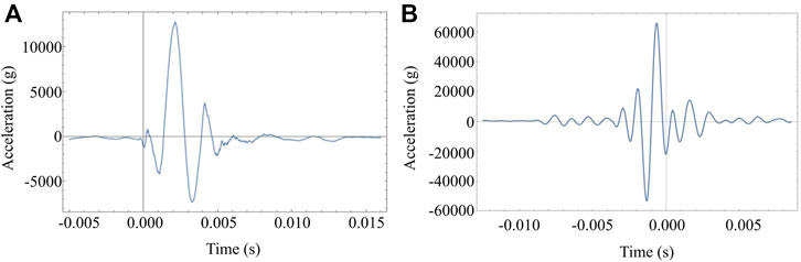
FIGURE 3. Acceleration profile plots from the first and third impact tests. The zero-point of the x-axis is arbitrary, making the axis useful for viewing the duration of the pulse during the impact event. (A) 12.7 k-g acceleration data after applying a low pass filter at 550 Hz. (B) 66 k-g acceleration data after applying a low pass filter at 1,000 Hz.
Post-Impact Mock Microfluidic Disk Inspection
All three test articles included a glass wafer in the place of a microfluidic device. The wafer casing type employed in each article is delineated in Supplementary Table SA and is discussed in greater detail in Cato et al. (2022), After the 12 k-g test, the glass wafer in the first test article had point fractures propagating from under the aluminum manifold openings and features. Nitrile film was placed above the baseplate (Figure 4A) and above the glass disk layer (Figure 4C). The fractures appeared to be correlated with deformable mass impacting the wafer (Figure 4C). Compression of the nitrile film (Figures 4B,D) from the aluminum manifold may have contributed to the impact events causing fracturing on impact. The 250 µm thick nitrile film had deformed at the actuator slots to accommodate for the displaced piezo actuators during impact and retained the deformation pattern post-impact (Figure 4D). After the 25 k-g test, the baseplate (Figure 5A) did not have any observable physical damage but the glass wafer had a similar fracture pattern hinting at the impact of unsecured masses inside the canister (Figure 5B). The fracture at the center of the manifold was likely due to inertia from the encapsulation compound used to fill cavity at the center, causing localized impacts and fracturing of the glass substrate (Figure 5D). The disassembled Test article #3 after the 50 k-g test is shown in Figure 6A. The fractures on the glass wafer appeared to have numerous microfractures but at similar locations as the previous impact tests (Figure 6B).
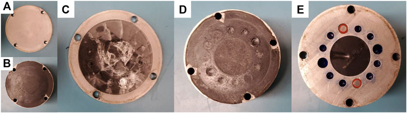
FIGURE 4. Disassembled Test article #1 after impact. (A) Baseplate. (B) Nitrile layer between the base plate and the ring housing the glass disk. (C) Glass disk inside the aluminum ring. (D) Nitrile layer between the glass disk and the potted portion of the canister. (E) Potted MCU board at the center and two piezo actuators in their slots.
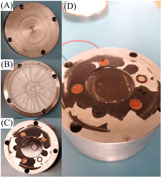
FIGURE 5. Disassembled Test article #2 after impact. (A) Baseplate. (B) Canister ring and PTFE cup housing the glass disk. (C) Potted canister core, three mock actuators, and one COTS piezo actuator in their slots. (D) Enlarged image.
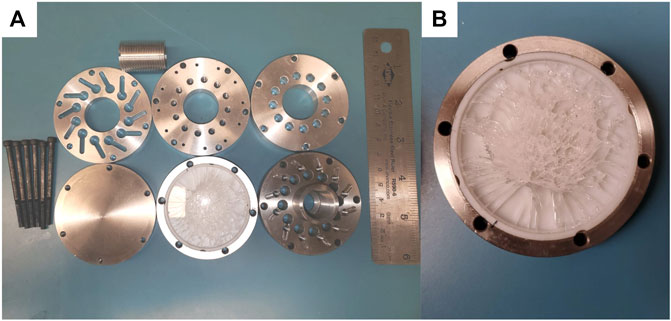
FIGURE 6. Test article #3 after impact. (A) Disassembled parts -- six canister plates, six bolts, and a lenstube. (B) Enlarged image showing the glass disk.
Post-Impact Microcontroller Board Testing
Test article #1 had a COTS Teensy microcontroller board potted in polyurethane. The disassembled test article #1 (Figure 4) shows the board encapsulated. There was no observable physical damage to the potting element (Figure 4E). The simplest code to generally test the functionality of MCU boards is the LED blink code. However, it could not be used in this case because the board potting material was opaque, and the blinking LED on the board was not visually observable. Therefore, a code for reading voltages on all the analog pins was uploaded to test the functionality of the MCU board and allowed to run for several seconds. The serial output screen showed a random voltage output confirming the software functionality of the board.
Post-Impact Piezoelectric Actuators Testing
The COTS micro piezoelectric actuators underwent 12 k-g and 25 k-g accelerations in Test articles #1 and #2. They were all subjected to X-ray imaging to test for wire bonding. The actuators have a simple construction with two copper wires bonded to a central cuboidal piezo element stack. Two intact wire bonds implied an operative actuator. Wire bonds to the piezo stacks were inspected at progressively higher magnification, x-ray power, and intensity settings. The piezo element stack had a density close to lead and showed up as a black block under x-ray without much scope for visualizing their contrast on the copper wires, which were of lower density. A top-view of the wire bonds was found to be the best way to check for bonding failure. The X-ray images of Test article #1 are shown in Figure 7. Figure 8 has the X-ray images of Test article #2.
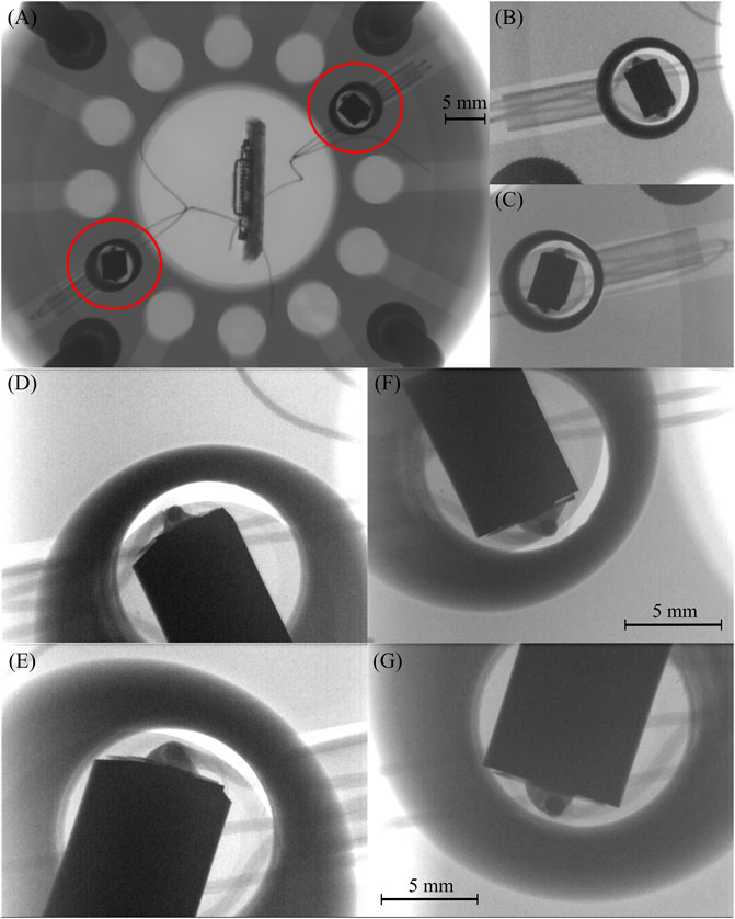
FIGURE 7. High-resolution x-ray images showing wire-bonding for both actuators on Test article #1. (A) Top x-ray image of the canister. The red circles indicate the piezo actuator placements. (B, C) Close-up x-ray image of the piezo actuators. (D–G) Close-up images showing the wire bonding on each side of the piezo-element stack.
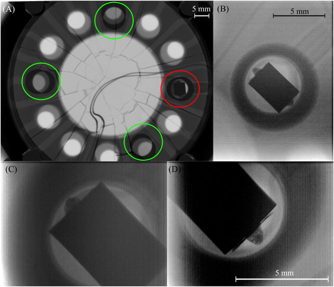
FIGURE 8. High-resolution x-ray images showing wire-bonding for the actuator on Test article #2. (A) Top x-ray image of the canister. The red circle indicates the piezo actuator placement. The green circles indicate the mock actuator placements. (B) Close-up x-ray image of the piezo actuator. (C,D) Close-up images showing the wire bonding on each side of the piezo-element stack.
Post-Impact Optical Component Testing
Test article #3 had a lens tube assembly inside a custom-made aluminum tube and was subjected to 50 k-g acceleration. After the impact test, the aluminum tube was easily removable from its canister slot implying there was no threading damage. The lens tube was subjected to X-ray imaging prior to disassembly, and the image was overlaid with a grid (Figure 9) to inspect component alignment after impact. The helix angle was determined to be 1.76 ± 0.17° by manually drawing lines diametrically from eight crests on the top of the image to their corresponding crests at the bottom and comparing them with the vertical grid line. The X-ray images were relatively low resolution and did not provide sharp, well-defined points to manually draw these lines with high accuracy, but given how the tolerance on the helix angle measurement was a mere 0.17°, this was a reliable technique to measure component alignment post-impact. The inclination of the optical filter was measured to be 1.87° by drawing lines along its optically active surface, and the inclination of the condenser lens was measured to be −0.80° by drawing a vertical line along its shoulder. The optical filter angle was within the tolerance of the helix angle and this led us to infer that it had not tilted upon impact. The condenser lens, however, is slightly rotated counterclockwise. The rounded shoulders of the lens could have contributed to a misalignment during assembly, or the shift could have occurred during impact. Due to the lack of X-ray imaging data of the assembly before impact, the cause for this misalignment cannot be ascertained.
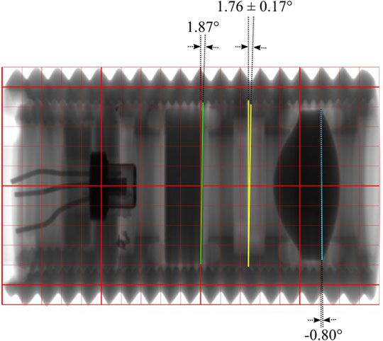
FIGURE 9. Lenstube optical component positional alignment test. Helix angle was measured to be 1.76 ± 0.17°. The inclination of the optical filter was 1.87°, and the condenser lens was −0.80°.
The disassembled lens tube components are shown in Figure 10A. Unscrewing the laser diode mount was easy and there was no observable threading failure in the top end of the tube. The laser diode was still firmly placed on the mount, but had a dislodged, broken optical window as anticipated. The optical window was made of glass and held in place by the can. Figure 10B is a brand-new laser diode of the same part number with an undamaged window compared to the impact-tested laser diode in Figure 10C.
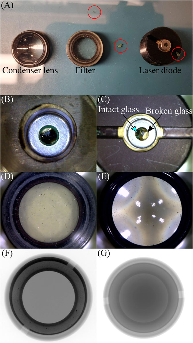
FIGURE 10. Impact-tested lenstube components from Test article #3. (A) Disassembled lenstube components. Broken shards of optical window glass of the laser diode are circled in red. (B) Microscope image of the new laser diode. (C) Microscope image of the impact-tested laser diode. (D) Impact-tested optical filter. (E) Impact-tested condenser lens. Minor internal thread damage due to impact is evident from the aluminum dust specks. (F) X-ray images of the filter showing no fractures. (G) X-ray images of the condenser lens show no fractures.
Retrieving the filter and the condenser lens from the tube was slightly harder but still possible -- the thread damage was not severe enough to lock the parts in place. Forcing them open by applying a slightly higher torque may have created aluminum dust that settled on the filter (Figure 10D) and the lens (Figure 10E). It is quite possible that the dust settled on the optical components during assembly. No microfractures were observed on either of the parts upon XRD inspection (Figures 10F,G).
The impact-tested laser diode’s opto-electrical performance was compared to that of a brand-new laser diode. The beam intensity distribution maps (Figures 11A,B) and the light-current-voltage (LIV) characteristic plots (Figures 11C,D) were slightly different. The beam intensity distribution map of the new laser diode was concentric with four circular disks, implying a uniform intensity distribution from the center. The beam radius of the new laser diode along the x and y axes varied only by 4.8%. The impact-tested laser diode, on the other hand, had a slightly jagged, but still concentric beam intensity distribution with a beam radius variation of 13.6% along the x and y axes. A major contributing factor to an uneven beam intensity distribution on the impact-tested laser diode is the partially broken window glass that was dislodged during impact, scattering light. The slightly elliptical beam shape could be due to the refraction of only a part of the laser beam at the broken glass window.
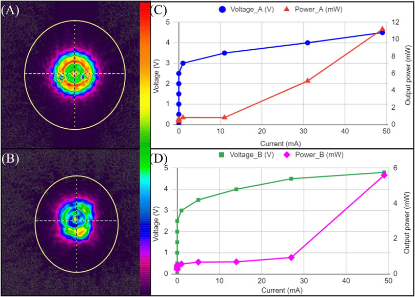
FIGURE 11. Impact-tested laser diode performance compared to a new laser diode. (A) New laser diode beam intensity distribution map. (B) Impact-tested laser diode beam intensity distribution map. (C) New laser diode light-current-voltage (LIV) curve. (D) Impact-tested laser diode LIV curve.
The beam area was 8.68% smaller with 50% lower optical output power on the impact-tested laser diode (Table 1). The reduction in output power is likely due to broken glass shards hitting and damaging the laser chip inside the can during the impact event. Impact test results show that the laser diode itself survived the impact, but custom packaging will likely be needed for ensuring complete resistance to impact. Using an aperture disk inside the can could be used to support the glass window and reduce the severity of this damage, but this technique requires further testing and validation.

TABLE 1. Laser diode performance comparison at the optimal voltage and current input parameters.
Post-Impact Manifold Geometry Testing
Deformation of the impacted canister bodies was inspected by subjecting them to X-ray imaging. Test article #1 was a full aluminum body and showed no deformation on the impact end (Figure 12). The aluminum baseplate had undergone elastic deformation during impact, consistent with COMSOL simulations that predicted a peak stress of 100 MPa at 12 k-g (Tamarin, 2002). Articles #2 and #3 had stainless steel on the baseplate and the plate housing the glass disks. Both articles had slightly expanded stainless steel canister plates implying a plastic deformation upon impact, inconsistent with COMSOL simulations that predicted a peak stress of 25 MPa at 50 k-g (Tamarin, 2002). These deformations can be clearly observed with a grid overlaid over the X-ray images in Figure 12. Inconsistencies between the simulated and experimental results can be attributed to computational models utilizing multiple physical assumptions to predict the outcome of a load, not all of which are true to the real-world scenario. The model assumes that all sections of the body are perfectly bonded together; this alters the force distribution because the entire surface is treated as a single unit. This assumption also contributed to a poor model for all press-fit components and did not predict their displacement upon impact. Further, the potting material was incorrectly assumed to be perfectly bonded in the model.
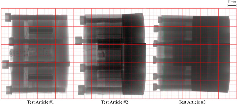
FIGURE 12. Post-impact test article manifold and bolt alignment visualization.
The X-ray imaging did not show any deformation of the steel bolts. Unfastening the M5 bolts was easy on articles #1 and #2, but article #3 had thinner M3 bolts and a slight bend on two of them was observable mechanically, but not visually. All six bolts on article #3 were retrievable despite the bend. Gowen et al. (2011) suggest titanium as an alternative to steel for lightness while offering high strength, but extensive characterization has not been carried out in the context of penetrators.
Conclusion
Planetary missions to astrobiologically significant worlds need access to subsurface samples for habitability analyses requiring complex, high-powered soft lander platforms that are large and heavy. Penetrator missions equipped with chemical analysis instruments fitting within small volume, mass, and power consumption envelopes have a great potential for enabling robust, distributed, low-cost science missions. IceShIP is a first-of-its-kind science payload platform for state-of-the-art analytical instrumentation employing a single-axis LIF system for detection of low concentration organic species. The design is small in size, low weight, and consumes low power, making it suitable for applications with small payload footprint requirements to meet the challenging demands of planetary science missions.
Here, we tested the survivability of multiple components of an LIF-based amino acid detection instrument for an IceShIP platform. Full survivability of linear piezoelectric micro-actuators, a microcontroller board, and optical components including a lens and filter was observed without significant structural support. Testing of a COTS laser diode package revealed survival of the diode, but not the packaging while all tests indicate that alternatives to glass for the microfluidic wafer, or alternative mounting strategies for glass should be explored and tested.
Future work can utilize strategies learned from the development of the test articles in this work. Reducing the mass and managing the mechanical loading on the glass wafers will be crucial for their survival. Polymer microdevice substrates could be a robust alternative to glass, and testing novel polymeric microdevices with a complete LIF assembly is warranted. Custom packaging designs must be explored to ensure physical survival of the laser diode during impact. While this was a hardware test, components were not configured to functionally conduct analytical measurements; we recommend that this testing be done in future work. COTS mini-actuators with limited failure modes might be explored as alternatives to the current piezo-based actuators, to satisfy needs for longer actuation lengths to facilitate fluidic movement within the chip. COMSOL modeling can and should be used for initial evaluation of test articles to guide impact tests, but modeling alone must not be relied on for high-g load survival assessments.
A cluster of IceShIP canisters could ride on an orbiting vehicle to be deployed at varying time intervals to achieve significant geographical distribution without the need for roving capabilities. A high reduction in payload size, weight, and power, and thus mission costs, could be achieved with microfluidic-based analytical instruments on a penetrator module in this study. All electrical and optical components tested in this work are currently commercially available and can be housed inside custom-machined manifolds to survive the large accelerations experienced during impact events. Impact-resistance, miniaturization, energy efficiency, and cost-effectiveness are pivotal for high-g load penetrator space-flight missions. This work satisfies these key aspects and demonstrates technology for a novel design for astrobiological in situ instrumentation.
Data Availability Statement
The original contributions presented in the study are included in the article/Supplementary Material, further inquiries can be directed to the corresponding author.
Author Contributions
CGR: Data collection, analysis, manuscript drafting process, and reporting out. MC: Design, fabrication, optimization, and analysis of the IMPOA test articles. NS: Microfluidic design, fluid actuation mechanisms, and optical design and testing. ZD: Optical design, testing, and optimization. PP: Co-investigator. Computational modeling and impact tests. JE: Computational modeling, impact tests, and reporting out. SF: Microfluidic design, testing, and fluid actuation mechanisms. JK: Co-investigator. Coordinated and advised microfluidic activities. AS: Primary investigator. Coordinated cross-institutional activities and advised all aspects of the work.
Funding
This work was supported by funding from the State of Georgia, the Georgia Institute of Technology, and NASA via the NASA Planetary Instrument Concepts for the Advancement of Solar System Observations (PICASSO, Grant# NNX15AM98G) program and the Small Business Technology [STTR, Grant# T8.03-9761 (STTR 2016-1)] program. Support for NS was provided via a NASA Postdoctoral Program (NPP) Fellowship. Support for ZD was provided via a NASA Space Technology Research Fellowship (NSTRF, Grant# NNX16AM82H). Support for CGR was provided by the NASA Future Investigators in Earth and Space Science and Technology (FINESST, Grant# 80NSSC20K1400) program. This work was performed in part at the Georgia Tech Institute for Electronics and Nanotechnology, a member of the National Nanotechnology Coordinated Infrastructure (NNCI), which is supported by the National Science Foundation (Grant# ECCS-1542174).
Conflict of Interest
Authors PP and JE were employed by company Sierra Lobo, Inc.,.
The remaining authors declare that the research was conducted in the absence of any commercial or financial relationships that could be construed as a potential conflict of interest.
Publisher’s Note
All claims expressed in this article are solely those of the authors and do not necessarily represent those of their affiliated organizations, or those of the publisher, the editors and the reviewers. Any product that may be evaluated in this article, or claim that may be made by its manufacturer, is not guaranteed or endorsed by the publisher.
Supplementary Material
The Supplementary Material for this article can be found online at: https://www.frontiersin.org/articles/10.3389/fspas.2022.943594/full#supplementary-material
References
Albee, A., Battel, S., Brace, R., Burdick, G., Casani, J., Lavell, J., et al. (2000). Report on the Loss of the Mars Polar Lander and Deep Space 2 Missions. NASA STIRecon Tech. Rep. N 00, 61967.
Blume, W. H. (2003). Deep Impact: Mission Design Approach for a New Discovery Mission. Acta Astronaut. 52, 105–110. doi:10.1016/S0094-5765(02)00144-3
Carden, H. D., and Mc Carty, J. L. (1968). Response Characteristics of Impacting Penetrometers Appropriate to Lunar and Planetary Missions. Washington, D. C: National Aeronautics and Space Administration. (No. NASA-TN-D-4454).
Cato, M. E., Govinda Raj, C., Speller, N. C., Duca, Z. A., Kim, J., Putman, P., et al. (2022). Icy Moon Penetrator Organic Analyzer (IMPOA) Impact Test Results. IEEE Aerosp. In press.
Corda, S. (2017). Introduction to Aerospace Engineering with a Flight Test Perspective. Germany: John Wiley & Sons.
Duca, Z. A., Speller, N. C., Cantrell, T., and Stockton, A. M. (2020). A Modular, Easy-To-Use Microcapillary Electrophoresis System with Laser-Induced Fluorescence for Quantitative Compositional Analysis of Trace Organic Molecules. Rev. Sci. Instrum. 91, 104101. doi:10.1063/5.0008734
Duca, Z. A., Speller, N. C., Cato, M. E., Morbioli, G. G., and Stockton, A. M. (2022). A Miniaturized, Low-Cost Lens Tube Based Laser-Induced Fluorescence Detection System for Automated Microfluidic Analysis of Primary Amines. Talanta 241, 123227. doi:10.1016/j.talanta.2022.123227
Ehrenfreund, P., Glavin, D. P., Botta, O., Cooper, G., and Bada, J. L. (2001). Extraterrestrial Amino Acids in Orgueil and Ivuna: Tracing the Parent Body of CI Type Carbonaceous Chondrites. Proc. Natl. Acad. Sci. U. S. A. 98, 2138–2141. doi:10.1073/pnas.051502898
Gowen, R. A., Smith, A., Fortes, A. D., Barber, S., Brown, P., Church, P., et al. (2011). Penetrators for In Situ Subsurface Investigations of Europa. Adv. Space Res. 48, 725–742. doi:10.1016/j.asr.2010.06.026
Hall, R. C. (1977). Lunar Impact: A History of Project Ranger. Scientific and Technical Information Office. Washington, DC: National Aeronautics and Space Administration.
Hand, K. P. (2017). Report of the Europa Lander Science Definition Team. National Aeronautics and Space Administration.
Higgs, P. G., and Pudritz, R. E. (2009). A Thermodynamic Basis for Prebiotic Amino Acid Synthesis and the Nature of the First Genetic Code. Astrobiology 9, 483–490. doi:10.1089/ast.2008.0280
Hopf, T., Kumar, S., Karl, W. J., and Pike, W. T. (2010). Shock Protection of Penetrator-Based Instrumentation via a Sublimation Approach. Adv. Space Res. 45, 460–467. doi:10.1016/j.asr.2009.08.015
Imbriale, W. A. (2006). Spaceborne Antennas for Planetary Exploration. Pasadena, CA: John Wiley & Sons.
Lorenz, R. D. (2011). Planetary Penetrators: Their Origins, History and Future. Adv. Space Res. 48, 403–431. doi:10.1016/j.asr.2011.03.033
McCarty, J. L., and Carden, H. D. (1967). Experimental Study of Vertical Impacts of an LM-Type Landing Gear Assembly under Simulated Lunar Gravity 56. NASA Technical Note (TN).
McCarty, J. L., Beswick, A., and Brooks, G. (1964). Application of Penetrometers to the Study of Physical Properties of Lunar and Planetary Surfaces (NASA Technical Note No. NASA TN D-2413). Hampton, VA: Langley Research Center.
Meech, K., A’Hearn, M. F., McFadden, L., Belton, M. J., Delamere, A., Kissel, J., et al. (2000). Deep Impact-Exploring the Interior of a Comet. Bioastronomy 213, 235.
National Research Council, Division on Engineering and Physical Sciences Space Studies Board (2012). Vision and Voyages for Planetary Science in the Decade 2013-2022. United States: National Academies Press.
Neveu, M., Hays, L. E., Voytek, M. A., New, M. H., and Schulte, M. D. (2018). The Ladder of Life Detection. Astrobiology 18, 1375–1402. doi:10.1089/ast.2017.1773
Pizzarello, S. (2006). The Chemistry of Life's Origin: A Carbonaceous Meteorite Perspective. Acc. Chem. Res. 39, 231–237. doi:10.1021/ar050049f
Saiki, T., Imamura, H., Arakawa, M., Wada, K., Takagi, Y., Hayakawa, M., et al. (2017). The Small Carry-On Impactor (SCI) and the Hayabusa2 Impact Experiment. Space Sci. Rev. 208, 165–186. doi:10.1007/s11214-016-0297-5
Saiki, T., Sawada, H., Okamoto, C., Yano, H., Takagi, Y., Akahoshi, Y., et al. (2013). Small Carry-On Impactor of Hayabusa2 Mission. Acta Astronaut. 84, 227–236. doi:10.1016/j.actaastro.2012.11.010
Scientific and Technical Aerospace Reports (1966). N66-28368-N66-29985. Washington, DC: NASA, Scientific and Technical Information Division, 16.
Smrekar, S., Catling, D., Lorenz, R., Magalhães, J., Moersch, J., Morgan, P., et al. (1999). Deep Space 2: The Mars Microprobe Mission. J. Geophys. Res. 104, 27013–27030. doi:10.1029/1999JE001073
Sridharan, R., Ahmed, S. M., Pratim Das, T., Sreelatha, P., Pradeepkumar, P., Naik, N., et al. (2010). The Sunlit Lunar Atmosphere: A Comprehensive Study by CHACE on the Moon Impact Probe of Chandrayaan-1. Planet. Space Sci. 58, 1567–1577. doi:10.1016/j.pss.2010.07.027
Strycker, P. D., Chanover, N. J., Miller, C., Hamilton, R. T., Hermalyn, B., Suggs, R. M., et al. (2013). Characterization of the LCROSS Impact Plume from a Ground-Based Imaging Detection. Nat. Commun. 4, 2620. doi:10.1038/ncomms3620
Surkov, Y. A., and Kremnev, R. S. (1998). Mars-96 Mission: Mars Exploration with the Use of Penetrators. Planet. Space Sci. 46, 1689–1696. doi:10.1016/S0032-0633(98)00071-3
Keywords: astrobiology, instrumentation, in-situ biosignature detection, astrobiology mission concepts, impact-penetrators
Citation: Govinda Raj C, Cato M, Speller NC, Duca Z, Putman P, Epperson J, Foreman S, Kim J and Stockton A (2022) Icy Moon Penetrator Organic Analyzer Post-Impact Component Analysis. Front. Astron. Space Sci. 9:943594. doi: 10.3389/fspas.2022.943594
Received: 13 May 2022; Accepted: 07 June 2022;
Published: 08 July 2022.
Edited by:
Hugh Kim, Korea University, South KoreaReviewed by:
Sangwon Cha, Dongguk University Seoul, South KoreaTae-Young Kim, Gwangju Institute of Science and Technology, South Korea
Copyright © 2022 Govinda Raj, Cato, Speller, Duca, Putman, Epperson, Foreman, Kim and Stockton. This is an open-access article distributed under the terms of the Creative Commons Attribution License (CC BY). The use, distribution or reproduction in other forums is permitted, provided the original author(s) and the copyright owner(s) are credited and that the original publication in this journal is cited, in accordance with accepted academic practice. No use, distribution or reproduction is permitted which does not comply with these terms.
*Correspondence: Amanda Stockton, YXN0b2NrdG9AZ2F0ZWNoLmVkdQ==