 S. S. Panini
 S. Narendranath2*
- 1Indian Institute of Astrophysics, Bengaluru, India
- 2UR Rao Satellite Centre, Indian Space Research Organisation, Bengaluru, India
- 3Indian Space Research Organisation, Bengaluru, India
Soft X-ray spectroscopy of the Sun is an important tool to understand the coronal dynamics and composition. The solar coronal X-ray spectrum below 1 keV is the least explored with high-resolution spectroscopy. Recent observations with Hinode XRT using coarse spectroscopy along with high-resolution imaging have shown that abundances in the coronae have variability associated with structures on the Sun. Disk averaged abundances with better spectral resolution spectrometers show time variability associated with flares. Both spatial and temporal variabilities seem to be related to changes in the magnetic field topology. Understanding such short term variabilities is necessary to model the underlying dynamics and mixing of material between different layers of the Sun. A Sensitive high-resolution spectrometer that covers the range in plasma temperatures and emission line complexes would uniquely reveal the entire evolution of flares. We are investigating a design of a multi-layer mirror-based X-ray spectrograph in the spectral range from 0.5 to 7 keV. The instrument operates in four asynchronous spectral channels operating one at a time. The multi-layer mirror placed at the focus of a Wolter type I telescope reflects a narrow band X-rays to the CCD which is placed at Nasmyth defocus. Converging X-rays from the front end optics helps to increase the spectral range of each channel while preserving the spectral resolution. This design is estimated to achieve a spectral resolution of 20 eV in the spectral range of 0.5–7 keV. With such high spectral resolution, we can resolve individual spectral features e.g., 6.7 keV Fe complex which can be used to diagnose high-temperature transient plasma during flares. The instrument design estimated performance and the science capabilities of this instrument will be discussed in detail in the paper.
1 Introduction
Solar coronal plasma is known to have a high temperature (1–2 MK) compared to the photosphere even during quiet periods (when no active regions are present). The coronal plasma across the solar disk is inhomogenous and changes as features develop at different spatial and temporal scales. Spectroscopic techniques in Far-UV to X-ray wavelengths have been used to study the evolution of plasma parameters such as electron temperature, densities, Differential Emission Measure and elemental abundances. The optically thin emission spectrum consists of a continuum and emission lines from highly ionized ions. In the soft X-ray regime, the continuum is a measure of the temperature and the emission line strengths that of the abundances. Systematic measurements of the plasma parameters from the pre-flare’ quiet sun phase to peak at uniform time bins is challenging given the large increase in the flux during such events. As a consequence, much of the past studies have focused on spectral evolution during flares and active regions. Also limited are high-resolution spectroscopic measurements in the <1 keV energy range, primarily due to the large flux.
This regime in X-ray wavelengths remains untapped despite its potential to answer several important questions pertaining to solar coronal heating:
• The quiet corona on an average has a temperature of 1.5 MK (Mackovjak et al., 2014). Variations and time scales of the quiet corona are an important input to current models of coronal heating.
• Does quiet corona harbor re connection, leading to micro-flares or nano-flares and are they accompanied by physical processes seen in active region flares such as magnetic re-connection, particle acceleration, shocks, waves, flow, evaporation, heating, cooling?
• Ishikawa et al. (2017) provided the first evidence for nano flare heated plasma in a non-flaring active region from the Focusing Optics X-ray Solar Imager (FOXSI-2) rocket sounding experiment. Evolution of plasma in such regions require high sensitivity instruments that can systematically trace the region.
• The low energy cut-off for the non-thermal power-law component is an important parameter to understand the energy partition between thermal and non-thermal regimes. Glesener et al. (2020) reported a value of 6.5 keV for a micro-flare observed with NuSTAR while for higher intensity flares the cut-off has been higher close to 10 keV (Aschwanden et al., 2019). Does this hold good in the quiet corona?
• The First Ionization Potential (FIP) bias varies in flares (Phillips et al., 2003; Katsuda et al., 2020; Narendranath et al., 2020) and active regions (Baker et al., 2015; Baker et al., 2019). Measurements of abundances in quiet regions and its possible variations are very limited. Ne and O (high FIP elements) measured in the solar wind (as Ne/O ratio) and with RESIK shows variations (Schmelz, 1993). The energy range ¡ 1 keV is thus important for understanding the FIP effect.
X-ray spectroscopy can be achieved either by the calibrated detectors using single-photon counting mode or by using dispersive elements such as gratings, crystals and multi-layer mirrors. Detector based spectroscopy provides a large bandwidth of operation but is limited by the low spectral resolution. Detector based spectroscopic instruments are suitable for cost effective operations and provide large band-width operation (Sylwester et al., 2008; Sylwester et al., 2012; Moore et al., 2018; Jain et al., 2008). Several dispersive elements provide very high resolution but cover small bandwidth in a given configuration. Over the last decade, X-ray imaging and spectroscopy have been implemented in several solar missions including SOHO (Malinovsky-Arduini and Froehlich, 1984), TRACE (Handy et al., 1999), HINODE (Kano et al., 2008), STEREO (Howard et al., 2000), SDO (Woods et al., 2002), RHESSI (Hurford, 2002), and STYX. X-ray spectroscopy in these instruments is implemented using the detector’s inherent spectral resolution when operated in the single-photon counting mode. Bragg crystal spectrometer (BCS) on-board Yohkoh satellite (Sylwester et al., 2005) used the graphite Bragg crystal to resolve the complex lines. Since the Bragg crystals have a very narrow band response, BCS used four channels (two for Fe lines, one for Ca and one for S) to study specific lines. Bragg crystals have unprecedented spectral resolutions of about 6,000 at 0.31 nm. BCS-Yohkoh has recorded the highest spectral resolution solar spectrum to date. However, due to the large field of view, it could only observe an averaged spectrum. Bragg crystal based monochromatic imaging instrument MgXII spectroheliograph, a part of CORONAS-F/SPRIT instrument (Zhitnik et al., 2003; Reva et al., 2012) provided deep insight to plasma temeperature and electron densities of Solar Corona. Soft X-ray telescope XRT (Kano et al., 2008) on the Hinode satellite has excellent imaging capability, determine an approximate temperature by taking filter ratios through multiple broadband filters. Focusing Optics X-ray Solar Imager (FOXSI) (Christe et al., 2017) flown on sounding rockets used direct imaging X-ray telescopes in the 3–70 keV energy range. Currently, Marshall Grazing Incidence X-ray Spectrometer (MaGIXS) (Athiray et al., 2019) is a grating-based solar X-ray spectrometer which operates from 0.5 to 2 keV under development for a rocket flight.
We have designed an instrument for the 0.5–7 keV energy range with high spectral resolution using multi-layer mirrors as dispersive elements. The instrument operates in four different spectral channels, one at a time, while the large effective area provided by the front end optics helps to reduce the integration time needed per channel, allowing fast switching between the channels. Independent channels also provide a provision to record dynamic events at high time resolutions in a single channel of scientific interest. The instrument can also be easily modified into an X-ray imaging telescope to image faint flares.
2 Instrument Design
The three major requirements of the instrument are large Bandwidth, high sensitivity and high spectral resolution. Single shell X-ray telescope is used at the front end to increase the photon collection capacity of the instrument. Multi-layer mirrors provide required spectral resolution but are limited in bandwidth. Band-width is increased by operating the instrument in four different channels by using a couple of mirrors in two different configurations. The instrument consists of three major components: Wolter type I front end telescope, multi-layer mirrors at the focus placed off-axis with respect to the optical axis, and an X-ray CCD at defocus position to capture the reflected X-rays from the multi-layer mirror. Figure 1 shows the simplistic schematic of the instrument for one channel. Two different multi-layer mirrors are used at two different angles in four asynchronous channels operating one channel at a time to cover different spectral regions. X-rays from the Sun undergo double reflection from the primary parabolic and secondary hyperbolic reflecting mirrors of the front end optics and gets focused on to a multi-layer mirror which is placed at a specific angle at the focus. Multi-layer mirrors consist of a series of thin alternative metallic and non-metallic layers deposited on a smooth substrate. When X-rays are incident on multi-layer mirrors above the critical angle, a narrow-band of X-rays are reflected at a given angle which is governed by the Bragg’s law. The energy of the reflected X-rays depends on the thickness of the coating materials and the angle of incidence of X-rays on the multi-layer mirror.
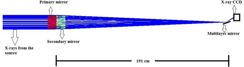
FIGURE 1. Schematic diagram showing the layout of the spectrograph. The X-ray telescope has a focal length of 191 cm. Multi-layer mirror is placed at the focus of the telescope at a specific angle to reflect the narrow band of X-rays to the detector at 10 cm defocus.
The front end optics is a single shell, gold-coated, Wolter type I optics with primary parabolic and secondary hyperbolic reflection. The diameter of the primary shell is 16 cm. The focal length of the telescope is 191 cm. The optics have an angle of incidence of 0.6° from the surface. The effective geometric area is 5.3 cm2. A 1 K × 1 K X-ray CCD is placed at the defocus position to record the reflected X-rays from the multi-layer mirror. X-ray CCD has a pixel size of 13.5 μm. X-ray CCD is also sensitive to the optical light. Since the Sun is the strong source of the optical light, a couple of optical light-blocking filters are used to reject the optical light and transmit the X-rays. First optical filter (Pre-filter) is placed at the entrance pupil of the X-ray telescope. The second filter (focal plane filter) is placed in front of the CCD. The visible light blocking requirement is of the order of 10−12. Hence each filter should have a rejection of 10−6. This requirement drives the minimum acceptable thickness for each filter. The visible light filter also has significant soft X-ray absorption. Hence thickness of the filters is optimized to have high visible-light blocking coefficient as well as less X-ray absorption. Mechanical stability of these filter to sustain the launching conditions also determines the materials and thickness of the filters. The pre-filter is a 125 nm Aluminum on a 250 nm Polyamide (C41H22N4O11). The focal length filter is a 600 nm Carbon on 250 nm Polyamide. Polyamide layer acts as a support structure to provide the required mechanical strength for the filters. Pre-filter also helps in keeping the optics from heating up during observation. Figure 2 shows the quantum efficiency of the X-ray CCD as provided by Teledyne-e2V with and without filters. From the figure, it is evident that the low energy X-rays are absorbed by the filters and hence reducing the quantum efficiency at the low energy region.
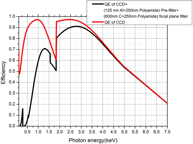
FIGURE 2. Quantum efficiency of the detector and the modification introduced by light filters.
2.0.1 Working Principle of the Spectrograph
In the spectrometer, the multi-layer mirror is placed at the focus at a particular angle with respect to the optical axis. Since the input beam from the X-ray telescope is a converging beam, X-rays make a cone of angles on the multi-layer mirror. An X-ray CCD is placed in the optical path 10 cm away from the focus. Since the detector is defocused, the spot size on the image plane is a circular annulus which represents the scaled version of the entrance pupil. When a multi-layer mirror is placed at an angle θ with respect to the optical angle, X-rays are incident on the mirrors with a cone of angles ranging from
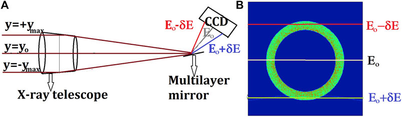
FIGURE 3. Working principle of the Spectrograph. (A) X-ray from different portions of the telescope are incident at different angles on the multi-layer mirror which reflects a range of energies. (B) Detector view when placed at 10 cm defocus as shown in Figure 1. Vertical axis contains the spectral information and the horizontal axis contains the spectral intensity information.
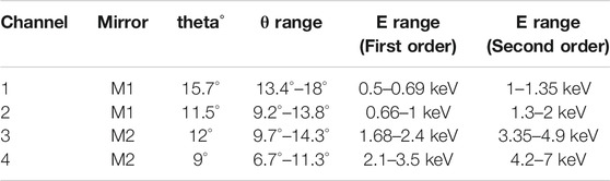
TABLE 1. Specifications of multi-layer mirrors and the positioning angles for all channels
2.0.2 Performance of the Spectrometer
M1 and M2 are W/B4C multi-layer mirrors with the thickness of bi-layers of 4 and 1.5 nm respectively. In-order to obtain high-reflectivity, 100 bi-layers are repeated in the multi-layer structure. Each bi-layer consist of two thin layers of Tungsten and Boron-Carbide. These multi-layers are fabricated on a smooth, flat Silicon wafers using magnetron sputtering technique to produce smooth and sharp interfaces between the Tungsten and Boron-Carbide layers. We have previously reported the fabrication procedure and studied the performance and stability of these mirrors (Singam et al., 2018a; Singam et al., 2018b).The ratios of Tungsten layer to the bi-layer thickness for each layer of multi-layer mirror is maintained at 0.33. This suppresses the third order Bragg peak from the multi-layer mirror. Reflection efficiency of higher order Bragg reflection from the multi-layer mirror are usually very low and can be neglected. Hence only first two significant Bragg orders are reflected from the multilayers.
From the optical design, it is noted that the first and second Bragg peaks are reflected at the same angle form the multi-layer mirror. Hence the photons from first and second order (typically twice the energy as the first order) reflection will incident at the same detector pixel. Hence it is not possible to spatially separate these photons. Hence we propose to use the X-ray CCD in single photon readout mode with spectrometer capability. The spectral resolution of X-rays CCDs operating in this mode is of the order of 100–150 eV at 1 keV (Bautz et al., 2004). Hence this coarse resolution is sufficient to separate first and second order from the multi-layers while the finer resolution is achieved by multilayer’s reflectivity that are spatially separated on the detector. Spectral resolution of the instrument in this configuration is governed by the Point Spread Function (PSF) of the telescope and the natural broadening of the Bragg peak of the multi-layer mirror. In the current configuration, the detector is sufficiently defocussed such that the spectral resolution is not limited by the PSF of the telescope. Rather, the spectral resolution for this design is driven by the natural Bragg peak broadening of the multi-layer mirrors. The resolution of a multi-layer mirror’s Bragg peak is dependent on several factors such as the number of bi-layers, angle of incidence, thickness of layer pairs, reflected energy and the order of Bragg reflection. As four different spectral channels with different specifications are used in the design, the spectral resolution of the instrument is not uniform through out the entire band-width of the instrument. Figure 4 shows the estimated spectral resolution of the instrument combined in all four channels. Each channel has both first and second order of reflection. Resolution of multi-layer mirrors increases as the order of the Bragg peak increases. The spectral resolution of the instrument is less than 20 eV for the major portion of the operation region. The instrument has the full field of view of 10’ which can cover an entire active region in the solar corona. The off-axis aberrations of the X-ray telescope affects the spectral resolution of the instrument at larger fields.
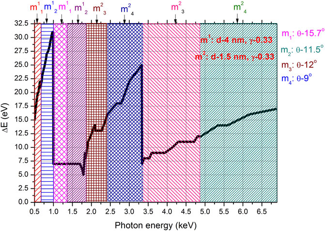
FIGURE 4. Estimated spectral resolution of the instrument combined in all four channels.Each channel has the first and second Bragg orders. m# represents two multi-layer mirrors with different coating specifications. m# indicates the four different angle of incidences of the mirror with respect to the optical axis as given in the inset.
The effective area of the instrument estimated by convolving the effective area of the front-end Wolter telescope with the energy dependent reflectivity of the multi-layer mirror and the quantum efficiency of the detector with filters. Since the multi-layer mirror reflects X-rays of different energies from different portions of the X-ray optics, the full geometric area of the optics is not used in spectrometer mode. As the angle of incidence of X-rays to ML mirror depends on the vertical axis of the telescope, the overall effective area of the telescope varies as a function of active reflecting area form the telescope as a function of photon energy. From Figure 3, the active area of the optics varies as the function of length of the chord which is maximum at y0 and gradually falls to zero at both the extreme ends. Hence at each channel, the effective area varies the profile of active area along y-axis as a function of energy. Effective area response of the spectrometer also varies significantly with the channel and the order of the Bragg peak. Figure 5 shows the estimated effective area of the instrument operating in spectrometer mode. The solar spectrum simulated for three temperatures from 1 to 14 MK involved with the response of the instrument in the spectroscopic mode (four channels combined) is shown in Figure 6. High resolution spectra of with a few seconds of time resolution is possible even down to 1 MK.
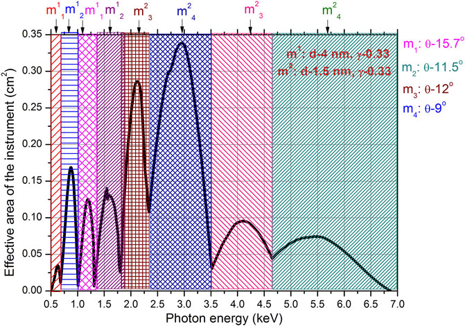
FIGURE 5. Effective area of the spectrometer combined in all four channels. m# represents two multi-layer mirrors with different coating specifications. m# indicates the four different angle of incidences of the mirror with respect to the optical axis as given in the inset.
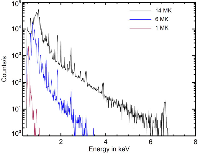
FIGURE 6. Expected solar spectrum in spectrometer mode (combined for the four channels) of the instrument. The spectrum is generated for a single temperature plasma using the Astrophysical Plasma Emission code based on AtomDB atomic data base.
2.1 X-Ray Imaging Telescope
The spectrometer can also be easily reconfigured into an X-ray imaging telescope during low solar activity. During weak flare conditions, the solar X-ray flux reduces several orders of magnitude. As the multi-layer mirror and the detector is placed on moving platforms for the spectrometer, there is a provision to physically move the X-ray CCD to the focus of the X-ray telescope to operate in the imaging mode.
The effective area of the instrument in the imaging mode is several orders of magnitude higher than the spectrometer. Hence the imaging mode can only be operated during low solar activity. The effective area in the imaging mode is estimated by convolving the effective area of the X-ray telescope with the efficiency of the X-ray CCD along with the absorption from optical light blocking filters. Figure 7 shows the estimated effective area of the instrument in the imaging mode. The field of view of the imaging telescope is limited to 0.1° to target small flares. As the effective area of the imaging telescope is very high, any bright event in the field can completely dominate the counts in the CCD. Hence the field of view is restricted using a custom designed central obscuration which also blocks ghost rays (single reflected and direct X-rays) reaching the X-ray CCD. Table 2 summarizes the design specifications of the instrument.
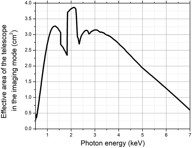
FIGURE 7. Effective area of the instrument in the imaging mode as a function of the photon energy.
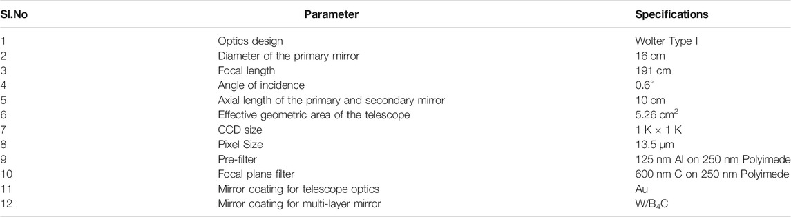
TABLE 2. Specifications of the instrument.
3 Summary
The proposed instrument design can provide spectral resolution around 20 eV over the large spectral band from 0.5 to 7 keV by using four different channels. The instrument is flexible to observe the entire broad spectrum as wells have the freedom to chooses a specific channel for observation at high temporal resolutions. Front end optics provides enough signal to observe the evolution of dynamic solar activities. At low activity levels, the configuration can be modified into pure imaging mode. The design is based on existing well-established technologies and thus is a potentially promising instrument for future small satellites.
Data Availability Statement
The original contributions presented in the study are included in the article/Supplementary Material, further inquiries can be directed to the corresponding author.
Author Contributions
All authors listed have made a substantial, direct, and intellectual contribution to the work and approved it for publication.
Conflict of Interest
The authors declare that the research was conducted in the absence of any commercial or financial relationships that could be construed as a potential conflict of interest.
Publisher’s Note
All claims expressed in this article are solely those of the authors and do not necessarily represent those of their affiliated organizations, or those of the publisher, the editors and the reviewers. Any product that may be evaluated in this article, or claim that may be made by its manufacturer, is not guaranteed or endorsed by the publisher.
References
Aschwanden, M. J., Kontar, E. P., and Jeffrey, N. L. S. (2019). Global Energetics of Solar Flares. VIII. The Low-Energy Cutoff. Astrophys. J. 881, 1. doi:10.3847/1538-4357/ab2cd4
Athiray, P. S., Winebarger, A. R., Barnes, W. T., Bradshaw, S. J., Savage, S., Warren, H. P., et al. (2019). Solar Active Region Heating Diagnostics From High-Temperature Emission Using the MaGIXS. Astrophys. J. 884, 24. doi:10.3847/1538-4357/ab3eb4
Baker, D., Brooks, D. H., Démoulin, P., Yardley, S. L., van Driel-Gesztelyi, L., Long, D. M., et al. (2015). FIP Bias Evolution in a Decaying Active Region. Astrophys. J. 802, 104. doi:10.1088/0004-637X/802/2/104
Baker, D., van Driel-Gesztelyi, L., Brooks, D. H., Valori, G., James, A. W., Laming, J. M., et al. (2019). Transient Inverse-FIP Plasma Composition Evolution Within a Solar Flare. Astrophys. J. 875, 35. doi:10.3847/1538-4357/ab07c1
Bautz, M. W., Kissel, S. E., Prigozhin, G. Y., LaMarr, B., Burke, B. E., and Gregory, J. A. (2004). “Progress in X-Ray CCD Sensor Performance for the Astro-E2 X-Ray Imaging Spectrometer,” in High-Energy Detectors in Astronomy. Editor A. D. Holland (Bellingham, WA: International Society for Optics and Photonics (SPIE), 111–122.
Christe, S., Shih, A. Y., Krucker, S., Glesener, L., Saint-Hilaire, P., Caspi, A., et al. (2017). “The Focusing Optics X-ray Solar Imager (FOXSI) SMEX Mission,” in American Geophysical Union, Fall Meeting 2017, San Diego, CA.
Glesener, L., Krucker, S., Duncan, J., Hannah, I. G., Grefenstette, B. W., Chen, B., et al. (2020). Accelerated Electrons Observed Down to 7 keV in a NuSTAR Solar Microflare. ApJl 891, L34. doi:10.3847/2041-8213/ab7341
Handy, B. N., Acton, L. W., Kankelborg, C. C., Wolfson, C. J., Akin, D. J., Bruner, M. E., et al. (1999). The Transition Region and Coronal Explorer. Sol. Phys. 187, 229–260. doi:10.1023/A:1005166902804
Howard, R. A., Moses, J. D., and Socker, D. G. (2000). “Sun-Earth Connection Coronal and Heliospheric Investigation (SECCHI),” in Instrumentation for UV/EUV Astronomy and Solar Missions, San Diego, CA. Editors S. Fineschi, C. M. Korendyke, O. H. Siegmund, and B. E. Woodgate (Society of Photo-Optical Instrumentation Engineers (SPIE) Conference Series), 259–283.
Hurford, G. (2002). “RHESSI Imaging Spectroscopy of Solar X-Rays,” in 34th COSPAR Scientific Assembly, Houston, TX.
Ishikawa, S.-n., Glesener, L., Krucker, S., Christe, S., Buitrago-Casas, J. C., Narukage, N., et al. (2017). Detection of Nanoflare-Heated Plasma in the Solar Corona by the FOXSI-2 Sounding Rocket. Nat. Astron. 1, 771–774. doi:10.1038/s41550-017-0269-z
Jain, R., Aggarwal, M., and Sharma, R. (2008). X-ray Emission from Solar Flares. J. Astrophys. Astron. 29, 125–145. doi:10.1007/s12036-008-0016-z
Kano, R., Sakao, T., Hara, H., Tsuneta, S., Matsuzaki, K., Kumagai, K., et al. (2008). The Hinode X-Ray Telescope (XRT): Camera Design, Performance and Operations. Sol. Phys. 249, 263–279. doi:10.1007/s11207-007-9058-7
Katsuda, S., Ohno, M., Mori, K., Beppu, T., Kanemaru, Y., Tashiro, M. S., et al. (2020). Inverse First Ionization Potential Effects in Giant Solar Flares Found from Earth X-Ray Albedo with Suzaku/XIS. Astrophys. J. 891, 126. doi:10.3847/1538-4357/ab7207
Mackovjak, Š., Dzifčáková, E., and Dudík, J. (2014). Differential Emission Measure Analysis of Active Region Cores and Quiet Sun for the Non-maxwellian κ-Distributions. Astron. Astrophys. 564, A130. doi:10.1051/0004-6361/201323054
Malinovsky-Arduini, M., and Froehlich, C. (1984). The Solar and Heliospheric Observatory, SOHO - A Phase-A Project of the European Space agency. Adv. Space Res. 4, 383–392. doi:10.1016/0273-1177(84)90214-X
Moore, C. S., Caspi, A., Woods, T. N., Chamberlin, P. C., Dennis, B. R., Jones, A. R., et al. (2018). The Instruments and Capabilities of the Miniature X-Ray Solar Spectrometer (MinXSS) CubeSats. Solar Phys. 293, 21. doi:10.1007/s11207-018-1243-3
Narendranath, S., Sreekumar, P., Pillai, N. S., Panini, S., Sankarasubramanian, K., and Huovelin, J. (2020). Coronal Elemental Abundance: New Results from Soft X-Ray Spectroscopy of the Sun. Sol.Phys. 295, 175. doi:10.1007/s11207-020-01738-5
Phillips, K. J. H., Sylwester, J., Sylwester, B., and Landi, E. (2003). “Solar Flare Abundances of Potassium, Argon, and Sulphur,” in AAS/Solar Physics Division Meeting, Laurel, MD.
Reva, A., Shestov, S., Bogachev, S., and Kuzin, S. (2012). Investigation of Hot X-Ray Points (HXPs) Using Spectroheliograph Mg Xii Experiment Data from CORONAS-F/SPIRIT. Sol.Phys. 276, 97–112. doi:10.1007/s11207-011-9883-6
Schmelz, J. T. (1993). Elemental Abundances of Flaring Solar Plasma: Enhanced Neon and Sulfur. Astrophys. J. 408, 373. doi:10.1086/172594
Singam, P. S., Nayak, K., Shyama Narendranath, K. C., Pradhan, P., Athiray, P., Sreekumar, P., et al. (2018a). Development of Multilayer Mirrors for Space-Based Astronomical X-ray Optics. J. Opt. 47, 91–95. doi:10.1007/s12596-017-0444-8
Singam, P. S., Nayak, M., Gupta, R., Pradhan, P. C., Majhi, A., Narendranath, S., et al. (2018b). Thermal and Temporal Stability of W/B4C Multilayer Mirrors for Space-Based Astronomical Applications. J. Astronom. Telesc. Inst. Syst. 4, 1–8. doi:10.1117/1.JATIS.4.4.044003
Sylwester, J., Gaicki, I., Kordylewski, Z., Kowaliński, M., Nowak, S., Płocieniak, S., et al. (2005). Resik: A Bent Crystal X-Ray Spectrometer for Studies of Solar Coronal Plasma Composition. Sol. Phys. 226, 45–72. doi:10.1007/s11207-005-6392-5
Sylwester, J., Kowalinski, M., Gburek, S., Siarkowski, M., Kuzin, S., Farnik, F., et al. (2012). SphinX Measurements of the 2009 Solar Minimum X-Ray Emission. Astrophys. J. 751, 111. doi:10.1088/0004-637x/751/2/111
Sylwester, J., Kuzin, S., Kotov, Y. D., Farnik, F., and Reale, F. (2008). SphinX: A Fast Solar Photometer in X-Rays. J. Astrophys. Astron. 29, 339–343. doi:10.1007/s12036-008-0044-8
Woods, T. N., Eparvier, F. G., Rottman, G. J., Judge, D. L., McMullin, D. R., Lean, J. L., et al. (2002). “Overview of the SDO Extreme Ultraviolet Variability Experiment (EVE),” in AGU Fall Meeting Abstracts, San Francisco, CA.
Zhitnik, I. A., Bugaenko, O. I., Ignat’ev, A. P., Krutov, V. V., Kuzin, S. V., Mitrofanov, A. V., et al. (2003). Dynamic 10 MK Plasma Structures Observed in Monochromatic Full-Sun Images by the SPIRIT Spectroheliograph on the CORONAS-F mission. Mon. Not. R. Astron. Soc. 338, 67–71. doi:10.1046/j.1365-8711.2003.06014.x
Keywords: solar corona, x-ray spectroscopy, X-ray telescope, multilayer mirror, X-rays
Citation: Panini SS, Narendranath S, Sreekumar P and Sankarasubramanian K (2021) Multilayer Mirror Based High-Resolution Solar Soft X-Ray Spectrometer. Front. Astron. Space Sci. 8:647828. doi: 10.3389/fspas.2021.647828
Received: 30 December 2020; Accepted: 07 June 2021;
Published: 26 July 2021.
Edited by:
Sergei Shestov, Royal Observatory of Belgium, BelgiumReviewed by:
Paola Zuppella, National Research Council, ItalyNikolai Chkhalo, Institute for Physics of Microstructures (RAS), Russia
Copyright © 2021 Panini, Narendranath, Sreekumar and Sankarasubramanian. This is an open-access article distributed under the terms of the Creative Commons Attribution License (CC BY). The use, distribution or reproduction in other forums is permitted, provided the original author(s) and the copyright owner(s) are credited and that the original publication in this journal is cited, in accordance with accepted academic practice. No use, distribution or reproduction is permitted which does not comply with these terms.
*Correspondence: S. S. Panini, c2luZ2FtLnBhbmluaUBnbWFpbC5jb20=; S. Narendranath, a2NzaHlhbWFAdXJzYy5nb3YuaW4=