 Joseph E. Borovsky
 Brian A. Bauer
 Michael Holloway
- 1Space Science Institute, Boulder Colorado, Boulder, CO, United States
- 2Johns Hopkins University/Applied Physics Lab, Laurel Maryland, Laurel, MD, United States
- 3Los Alamos National Laboratory, Los Alamos New Mexico, Los Alamos, NM, United States
MIO (Magnetosphere-Ionosphere Observatory) is designed to definitively fix a cause-and-effect problem: In the nightside magnetosphere-ionosphere system we don’t know what is connected to what. The MIO mission concept is to operate a powerful 1-MeV electron accelerator on a main spacecraft in the equatorial nightside magnetosphere: the electron beam is directed into the atmospheric loss cone to deposit ionizing electrons in the atmosphere sufficient to optically illuminate the magnetic footpoint of the spacecraft while 4 nearby daughter spacecraft make equatorial magnetospheric measurements. A network of ground-based optical imagers across Alaska and Canada will locate the optical beamspot thereby unambiguously establishing the magnetic connection between equatorial magnetospheric measurements and ionospheric phenomena. Critical gradient measurements will be made to discern magnetospheric field-aligned-current generator mechanisms. This enables the magnetospheric drivers of various aurora, ionospheric phenomena, and field-aligned currents to be determined. In support of the Solar and Space Physics (Heliophysics) 2022 Decadal Survey, an experienced team of engineers and scientists at The Johns Hopkins University Applied Physics Laboratory (APL) have developed a NASA HMCS (Heliospheric Mission Concept Study) mission concept that can achieve the science objectives. The mission concept presented here is the result of trade studies that optimized the mission with regard to factors such as science objectives, concept study requirements, space environment, engineering constraints, and risk. This Methods paper presents an overview of the MIO concept.
1 Scientific motivation for MIO
Insufficiently accurate magnetic-field-line mapping between the equatorial nightside magnetosphere and the ionosphere/atmosphere prevents the space-physics community from determining the causes of the diverse types of aurora and ionospheric phenomena and from knowing many of the connections in the magnetosphere-ionosphere-thermosphere system. The bold MIO mission concept uses a powerful 1-MeV electron accelerator fired from the equatorial nightside magnetosphere: with the beam directed into the atmospheric loss cone the accelerator optically illuminates the magnetic footpoint of the spacecraft in the atmosphere (cf. Figure 1). Four nearby daughter spacecraft make equatorial magnetospheric gradient measurements (cf. Figure 1). 1 MeV was chosen as the beam energy to optimize several factors in a trade study, discussed in Section 5. A network of 29 ground-based optical imagers in Alaska and Canada locate the optical beamspot, thereby unambiguously establishing the connection between the equatorial magnetospheric measurements and ionospheric phenomena. Critical gradient and boundary measurements will be made to discern magnetospheric generator mechanisms and boundary mapping.
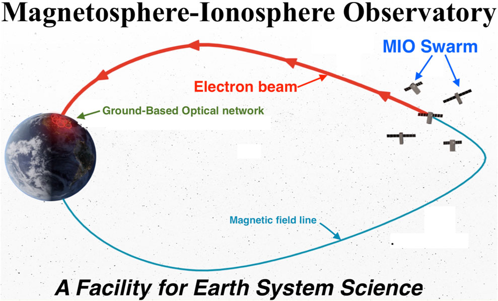
FIGURE 1. A depiction of the MIO mission configuration, which includes a main spacecraft operating a relativistic-electron accelerator, 4 nearby daughter spacecraft making gradient measurements, and a ground-based optical network covering Canada and Alaska.
Magnetic-field models are not accurate enough in the dynamic nightside magnetosphere to establish detailed magnetosphere-ionosphere connections and it is unlikely that breakthroughs in these models will be achieved. Examples of the poor results of magnetic-field-line mapping with models can be found in Thomsen et al., 1996, Weiss et al., 1997, Ober et al., 2000, Shevchenko et al., 2010, and Nishimura et al., 2011. “Magnetosphere-to-Ionosphere Field-Line Tracing Technology” using an energetic electron beam fired from a magnetospheric spacecraft was called out in the National Research Council 2013 Solar and Space Physics Decadal Survey [National Research Council, 2013, pp. 333-334] as an “instrument development need and emerging technology” that 1) is in need of a technology boost and that 2) could have a substantial impact in solar and space physics. The MIO research team of accelerator physicists, plasma physicists, instrument designers, space engineers, system engineers, and magnetospheric and ionospheric scientists has responded to that Decadal-Survey call, culminating in a NASA-sponsored Heliospheric Mission Concept Study (HMCS) mission point design.
The Magnetosphere-Ionosphere Observatory (MIO) mission is designed to conclusively fix a major gap in our knowledge of system-level dynamics: the gap that in the multiply-connected magnetosphere-ionosphere system we don’t know what is connected to what. Specifically, we don’t know what fundamental magnetospheric processes drive the diverse ionospheric and auroral phenomena and we don’t know what form of energy is extracted from the nightside magnetosphere and transferred to the ionosphere and atmosphere. An important example is the longstanding question of how the magnetosphere drives quiescent low-latitude (growth-phase) auroral arcs: a large number of diverse generator mechanisms have been hypothesized (reviewed over the decades by e.g. Falthammar 1977, Atkinson 1978, Swift 1978, Borovsky 1993, Paschmann et al., 2002, Haerendel 2011, 2012, Hearendel, 2022, and Borovsky et al., 2020a) but equatorial magnetospheric measurements have not been unambiguously connected to arcs in the ionosphere, preventing scientists from identifying the correct generator mechanisms. The dilemma is similar for other types of aurora and ionospheric phenomena. The heliospheric community does not yet understand the energy-conversion processes in the equatorial magnetosphere that drive these near-Earth processes; and the community does not understand the origins of the Alfvenic energy that drives some of the nightside aurora. This broad knowledge gap underlies the decades-old question of how the magnetosphere drives aurora and underlies the more-modern problems of how the magnetosphere drives other ionospheric phenomena such as SAPS, SAID, STEVE, and ionospheric density irregularities. MIO will decisively fix this gap by unambiguously connecting the magnetosphere and its physical processes to the ionosphere and its diverse phenomena. By making the unambiguous magnetosphere-ionosphere connection MIO will be able to finally elucidate the main drivers of major ionospheric space-weather phenomena and establish a fundamental link to reveal how energy flows between the magnetosphere and the ionosphere. MIO is the result of substantial technology development and will provide the magnetospheric, ionospheric, and atmospheric communities with a unique scientific facility. See Table 1 for a catalog of MIO uses for Earth system science.
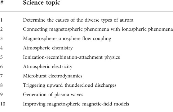
TABLE 1. Summary of the science of MIO for the diverse Earth-system-science communities: see also Sanchez et al., 2019, Marshall et al., 2019, and Borovsky et al., 2020c and in particular the Appendix of Borovsky et al., 2020b for details and references.
This paper is organized as follows. Section 2 presents a high-level overview of the MIO mission. Section 3 outlines the goals and objectives of MIO. Section 4 describes the basic mission architecture of MIO. Section 5 describes the innovative space-based design of the MIO 1-MeV electron accelerator. Section 6 details the payload of the MIO mother and daughter spacecraft and the ground optical facilities. Section 7 discusses the mission operations. Section 8 overviews the risk and costs of MIO.
2 The Magnetosphere-ionosphere observatory mission overview
The MIO mission concept (Figure 1) is to operate a powerful electron accelerator (beam energy 1 MeV, beam power 1 kW) on a main spacecraft (see Figure 2) in the equatorial nightside magnetosphere with the beam directed into the atmospheric loss cone to optically illuminate the magnetic footpoint of the main spacecraft. Four nearby (100s of km apart) daughter spacecraft make magnetospheric measurements. The optical beamspot in the atmosphere is located using a network of 29 TREx (Transition Region Explorer) ground-based optical imagers that covers Canada and Alaska (cf. Figure 3). MIO thereby unambiguously establishes the magnetic connection between magnetospheric measurements and ionospheric phenomena.
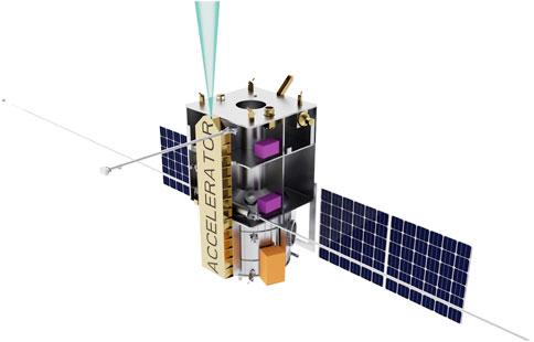
FIGURE 2. The non-spinning mother spacecraft carrying the electron Accelerator. The green cone is the range of magnetic steering of the relativistic electron beam.
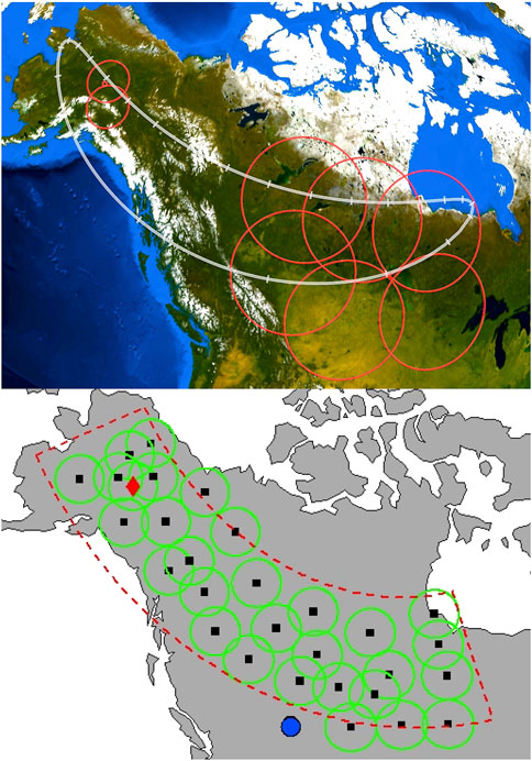
FIGURE 3. (Top Panel) An estimate of the 24-h magnetic-footpoint track (gray) of the MIO swarm in its 4.3 × 9 RE 24-h orbit at a magnetospheric-activity level of Kp = 2: the large red circles are the fields of view of the present-day TREx camera network and the smaller red circles are the ranges of the PFISR and HAARP ionospheric facilities. (Bottom Panel) The locations costed for the extended TREx array of 29 optical imagers (black squares): the red triangle is Fairbanks between the locations of the PFISR and HAARP ionospheric facilities and the blue dot is the location of the University of Calgary ground station.
A 4.3 × 9 RE low-inclination (quasi equatorial) orbit with a 24-h period is chosen such that the magnetic footpoint of MIO is always over Canada-Alaska (see top panel of Figure 3). MIO is designed to have a regular beam firing every 5 min to make a magnetosphere-ionosphere connection every 5 min in the orbit, with extra beam firings triggered by onboard magnetospheric measurements of boundary crossings or triggered by a scientist-in-the-loop monitoring the ground-based imaging.
On the main spacecraft it is essential to accurately know the direction of the local magnetic field to be able to point the accelerator beam into the atmospheric loss cone. In actuality the northern and southern atmospheric loss cones for energetic electrons both are shifted eastward from the magnetic-field direction owing to finite-gyroradii effects in the magnetosphere Mozer, 1966; Il’in et al., 1992; Il’ina et al., 1993; Porazik et al., 2014: the MIO Science Team has put in significant efforts to understand and predict this angular shift Borovsky et al., 2022a, 2022b; Borovsky, 2022a. (As discussed in Section 4, this loss-cone-shift effect to some degree restricts the selection of the MIO orbit.). Non-spinning spacecraft can suffer from magnetometer offsets preventing the magnetometer from accurately determining the magnetic-field direction. An electron-drift instrument (EDI) on the non-spinning main spacecraft overcomes this problem by accurately determining the direction of the local magnetic field, enabling magnetometer offsets to be corrected. When the accelerator electron beam is fired, about 0.001°C of negative charge is removed from the main spacecraft and the main spacecraft could be subject to uncontrolled spacecraft charging. The MIO Science Team has made significant progress in understanding how to mitigate this accelerator-induced charging Delzanno et al., 2015a, 2015b, 2016; Lucco Castello et al., 2018: on the main spacecraft it is essential to operate a plasma contactor to prevent catastrophic spacecraft charging during accelerator-beam operations.
To be successful MIO must make measurements in the magnetosphere to identify magnetospheric regions (e.g., electron plasma sheet, ion plasma sheet, remnant layer, plasmasphere, lobes), magnetospheric boundaries (e.g., plasmapause, inner edge of electron plasma sheet, plasma sheet boundary layer), and magnetospheric phenomena (e.g., velocity shears, plasma waves, ULF waves, substorm particle injections). These measurements are made with electrostatic analyzers (ESAs), magnetometers, EDI, and plasma-wave instrumentation. For auroral physics, measuring the magnetospheric electric field is essential: EDI makes that measurement. The ESAs are on the four daughter spacecraft. To make the clearest identifications of the magnetospheric generator mechanisms driving field-aligned currents (including auroral field-aligned currents) the four daughter spacecraft measure critical gradients in the magnetosphere: gradients in n, Ti, Te, Pi, Pe, v, and B so that the various terms in the current-generator equation (cf. Eq. 1 of Borovsky et al. [2020b])
can be evaluated. Here j|| is the field-aligned current density, ω = ∇×v is the vorticity, ρ is the plasma mass desity, L is the length of the generator region along the field line (j||/L–dj||/dL), and the || subscript means parallel to the local magnetic field B. Each term in the generator equation involves one perpendicular-to-B gradient crossed with another perpendicular-to-B gradient: hence the orbits of the 4 daughter spacecraft are designed to simultaneously measure radial gradients and azimuthal (local-time) gradients in the equatorial magnetosphere. Another current-generation mechanism involves Hall currents: to detect and quantify Hall currents the ion and electron cross-field velocities must be separately measured. To do this the ESAs measure the ion velocity and the EDI measures the electron velocity.
For the operation of the MIO mission, several technical issues had to be studied and overcome. The Appendices of Borovsky et al., 2022c discuss the critical issues of temporal evolution of the electron beam, relativistic-electron beam stability, pitch-angle scattering of the beam electrons by ambient magnetospheric plasma waves, optical beamspot detection, statistics of cloud cover at the ground-camera sites, and safe operations of the accelerator in space (which includes mitigating spacecraft charging during the beam firings).
Community use of MIO is possible via 1) conjunctions with low-altitude spacecraft, 2) collaboration with global ionospheric radars, 3) conjunctions with incoherent-scatter (ISR) radars and ionospheric heaters (cf. Figure 3), and 4) ground-based ionospheric and atmospheric instrumentation fielded along the footpoint path (cf. Figure 3). In Table 1 bold and innovative scientific uses of MIO are listed for the diverse Earth-science communities. Via scientific campaigns with the magnetospheric, ionospheric, and atmospheric communities MIO will serve as a meta-instrument for Earth System Science Borovsky and Valdivia, 2018.
3 Magnetosphere-ionosphere observatory goals and objectives
MIO addresses unsolved scientific questions about the physics of energy flow and cause and effect within the interconnected magnetosphere-ionosphere system. MIO focuses on the “weakest link” in our understanding of the coupled system, which is the fact that we don’t know what couples to what! The MIO mission will conclusively fix that key knowledge gap throughout the complex nightside magnetosphere-ionosphere system.
The overarching science goal of the MIO mission is to Determine the magnetospheric processes that drive multiple types of aurora, multiple ionospheric phenomena, and field-aligned currents and to determine the multiple unknown connections in the magnetosphere-ionosphere system.
The overarching objective of MIO is to Unambiguously connect magnetospheric measurements to ionospheric phenomena. This is accomplished with the mission objective to regularly connect magnetospheric measurements to an observed beamspot in the ionosphere-atmosphere.
Specific objectives of MIO are to make the connected measurements to:
Objective 1. Determine to what regions in the magnetosphere the various auroral forms and the various ionospheric phenomena map.
Objective 2. Determine to where in the ionosphere magnetospheric regions, boundaries, and events map.
Objective 3. Determine what processes in the magnetosphere produce the various auroral forms and ionospheric phenomena.
Objective 4. Determine in what ways the magnetosphere drives field-aligned currents.
The MIO mission will determine what forms of energy are converted in the magnetosphere to drive ionospheric phenomena, enabling us to better understand the impact on the magnetosphere of its driving of the ionosphere. Tests of the diverse theories of auroral generators can finally be made. And the MIO mission, with collaboration with global radars, can test M-I-coupling ideas about where the magnetosphere is driving ionospheric convection versus where the ionosphere is driving magnetospheric convection. Suspected connections between the ionosphere and the magnetosphere can be definitely confirmed or refuted. MIO will be the Rosetta Stone to finally enable views of the dynamic aurora to be interpreted as a TV screen depicting what is going on in the nightside magnetosphere and magnetotail [e.g. Akasofu, 1965; Mende, 2016a,b].
A science traceability matrix (STM) for meeting the goals and objectives can be found in Borovsky et al., 2022c.
More details about the science and the mission concept can be found in Borovsky 2002; 2022b and in Borovsky et al., 2020b, 2022c.
4 The basic mission architecture
The MIO concept study was performed at The Johns Hopkins University Applied Physics Laboratory (APL) concurrent engineering laboratory (ACELab) (Smith et al., 2021). The MIO Engineering Team personnel are listed in Table 2 and the MIO Science Team personnel interacting with the engineering team are listed in Table 3. The engineering team arrived at a concept representing a mission point design at Concept Maturity Level (CML) 4, understanding trades and development to be conducted in subsequent mission phases, and identification of mission-level risks and mitigations. The result is a well-defined, feasible mission that accomplishes the science goals at reasonable cost and with low schedule risk. The team therefore recommends MIO as the best concept for determining the magnetic connections between the Earth’s magnetosphere and ionosphere.
Mission and spacecraft design features of the MIO concept include the following
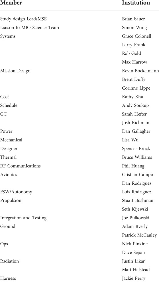
TABLE 2. The MIO HMCS engineering team at the applied physics lab.
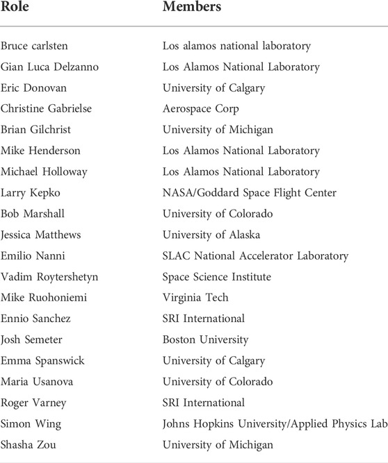
TABLE 3. The MIO HMCS Science Team membership.
A non-spinning mother spacecraft with four spinning daughter spacecraft in a 4.3 × 9 RE, 24-h orbit with inclination <5° (2° was chosen for the study in order to avoid conflict with the geosynchronous-orbit belt). The daughter spacecraft are equally spaced around the mother in a 200 × 400 km relative orbit. All spacecraft are powered by solar panels.
The eastward shift of the atmospheric loss cone (both the northern and the southern loss cones) for beam electrons limits where in the nightside magnetosphere MIO can be successfully operated: avoidance of large shifts drives the orbit selection for MIO. In a dipole magnetic field the angular shift is easy to predict [e.g., Borovsky et al., 2022a] and so the operators know where to aim the accelerator relative to the local magnetic-field direction. However, in some of the non-dipolar-field regions of the nightside magnetosphere predicting where to aim is a guess (Borovsky, 2022a). In Figure 4 is a map of the magnitude of the loss-cone angular shift eastward in the nightside magnetosphere when Canada is at local midnight near the December solstice. The map was created using the Tsyganenko T96 (Tsyganenko, 1995; Tsyganenko and Stern, 1996) magnetic-field model to calculate the magnetic-field strength B and the local (B × ∇B) curvature of the magnetic-field lines. Magnetic-field lines are drawn in black. Note that there is a strong “dipole tilt” to the field in the Canadian sector with the dipole equator southward from the geographic equator. The purple line segments in Figure 4 denote the planes of 4.3RE-by-9RE orbits with different inclinations as labeled. The yellow-shaded zones in Figure 4 are regions of the magnetosphere where the atmospheric loss cone angular shift is small (<0.5°) and hence where the aiming of the MIO electron beam along the magnetic field is certain to hit the atmospheric loss cone. For comparison, Figure 5 plots the half-angle θl.c. Of the atmospheric loss cone (colors) for the same dipole tilt as Figure 4 and labeling the same orbital inclinations for MIO. In choosing the orbit it is very desirable 1) to not operate the MIO 1-MeV electron accelerator in regions that are not yellow, 2) to operate the beam as close as possible to the non-yellow regions (where auroral-generation physics is suspected to be highest), and 3) to not operate the MIO accelerator in regions where the beam needs to pass through a non-yellow region to get to the northern ionosphere. (In those large-shift regions the electron orbits become stochastic (Borovsky et al., 2022a,b).) Hence, orbits with inclinations near 0° are most desirable from a mission-objective point of view. During other times of the year (away from the December solstice) the picture in the nightside magnetosphere is very similar, with large loss-cone shifts in the region associated with the cross-tail current sheet.
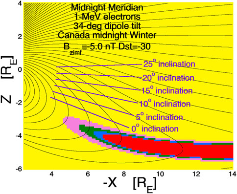
FIGURE 4. Magnetic-field lines in the nightside magnetosphere in the noon-midnight meridian are drawn as the black curves using the T96 magnetic-field model. The dipole equator on the nightside is tipped 34° southward, representing the dipole tilt at the December equinox when Canada is at local midnight. At this time the Earth’s spin axis is tilted away from the Sun by 23° and the dipole is tilted a further 11°. In the plot Z is the north-south direction and X is the Sun-Earth direction. The approximate orbital planes of a 4.3RE-by-9RE MIO orbit are drawn as the line segments labeled for the various orbit inclinations. The colored shading is the calculated eastward shift of the local atmospheric loss cone for 1-MeV electrons based on the local magnetic-field strength and the local radius of curvature of the magnetic field lines calculated in the T96 magnetic-field model. The color scheme is yellow (shift <0.5°), pink (shift 0.5°–1°), green (shift 1°–1.5°), blue (shift 1.5°–2°), and red (shift > 2°). Essentially, it is prudent to operate the MIO Accelerator only in the yellow shaded zones.
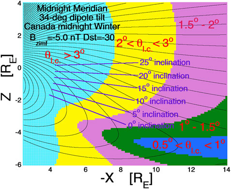
FIGURE 5. Same parameters as Figure 4, but the half-angle of the atmospheric loss cone θλc is plotted in color. In the light-blue shaded region θl.c. > 3°, in the yellow region 2° < θl.c < 3°, in the pink shaded region 1.5° < θl.c < 2°, in the green shaded region 1° < θl.c < 1.5°, and in the blue shaded region 0.5° < θl.c < 1°.
For the 4.3 × 9 RE orbit the launch C3 (characteristic energy) ≤ 0 km2/s2 for a launch from Cape Canaveral that includes inclination change and apogee insertion. After apogee insertion to 9 RE the mother spacecraft will then perform the 886 m/s perigee raise maneuver to 4.3 RE before releasing the 4 daughters.
For disposal, all spacecraft will perform a 242 m/s maneuver to raise their 4.3-RE orbit perigees above geosynchronous-orbit (6.6 RE).
Nominal Operations: Payloads onboard Mother and Daughters on and collecting data. The mother spacecraft is oriented so that the solar arrays are on the Sun.
Accelerator Operations: accelerator is firing three 0.5-s pulses spaced 0.5 s apart (like a Morse code S) with a 3-burst firing every 5 min. An array of TREx optical ground sensors observe the beam pulses as the pulses interact with the Earth’s upper (−60 km) atmosphere. Additional beam pulses may be triggered via magnetospheric-boundary-crossing detection onboard the spacecraft or via ground-operator command.
Daughters are relaying magnetometer and ESA plasma data to the mother every 12 s for boundary detection. Accelerator operations only take place when there are dark skies at the magnetic ground point and interference from the moon and clouds is minimal.
The mother spacecraft (cf. Figure 2) is a 1,660 kg wet mass, 3-axis-stabilizized spacecraft with 779 kg dry mass, 183 kg payload, 6.2 m2 solar arrays, and 1,334 m/s pressurized monopropellant propulsion.
The 4 daughter spacecraft are 87 kg wet mass, 5 RPM spinning spacecraft with 70 kg dry mass, 5.3 kg payloads, and 330 m/s blowdown monopropellant propulsion.
S-band uplink, downlink, and crosslinks provide 2,250 Gbits of total mission science data return and allow mother to autonomously detect magnetospheric boundary crossings.
The Mission Operations Center/Science Operation Center ground systems perform all functions needed to operate the mission, coordinate operations with the ground sensors, return data through the near-Earth network (NEN), distribute science and engineering data to the science teams, and analyze and archive mission data.
A small dedicated antenna will be located at the University of Calgary for operator-commanded pulsing and enabling/disabling accelerator operations on a science-target and weather basis.
The engineering team determined Technology Readiness Levels (TRLs) for spacecraft subsystem elements and instruments. All components of the spacecraft are at TRL 6 or higher. Where possible, the instruments included in the payload are based on previously flown instruments that would allow the mission to be flown now without technology development. The only exception is the accelerator, which is currently TRL 4 and needs work to advance its technology readiness prior to preliminary design review (PDR).
5 The Magnetosphere-ionosphere observatory electron accelerator
For the MIO mission concept to be successful, a powerful electron beam fired from the equatorial magnetosphere must go into the atmospheric loss cone. Typically the loss cone has a half angle of 1°–3° (cf. Figure 5). The power P of an electron beam is P = IV, where I is the beam current and V is the beam energy (Voltage). High-current beams have more space charge and the beam space charge leads to transverse electrostatic expansion of the beam after it exits the Accelerator, enlarging the angular divergence of the electron beam. The beam divergence must be kept small compared to the angular size of the loss cone so that the beam power can be deposited within the loss cone. Hence, to get high beam power, low I and high V are desirable. (There are also other tradeoffs to consider when choosing I versus V: cf. Borovsky et al., 2020c, Sect. 4 and Table 2 of Borovsky et al., 2020b, and Sect. A.2.2 of Borovsky et al., 2022c. Older-generation spaceflight DC-gun electron beams [e.g., Winckler et al., 1975; Winckler, 1992; O’Neil et al., 1978; Rapport et al., 1993; Prech et al., 1995, 2002, 2018; McNutt et al., 1995; Raitt et al., 1995] are limited to about 50 keV in beam energy: for 1-kW of beam power they suffer from an unacceptably large beam divergence. Hence, a completely new space-based accelerator design is needed for MIO.
A team of accelerator scientists and engineers at Los Alamos National Laboratory and at the SLAC National Accelerator Laboratory has been developing a novel 1-MeV space-based accelerator technology that enables the MIO mission (Lewellen et al., 2019). The beam energy of 1 MeV was chosen to optimize a number of factors in the trade study between beam energy and beam current: those factors include engineering practicality, power efficiency, beam divergence, loss-cone-shift effects, beam steering, spacecraft charging, and quenching of atmospheric optical emission (cf. Table 2 of Borovsky et al., 2020b).
The all-solid-state RF system is the key innovation that enables the MIO Accelerator design. The Accelerator is based on driving 5.1-GHz (C-band) radio-frequency (RF) cavities using high-electron mobility transistor (HEMT) high-power, solid-state amplifiers. Each cavity is directly driven by a pair of these devices. Each gallium nitride (GaN) HEMT amplifier is capable of generating up to 500 W (peak) of RF power at C-band with about 50% efficiency, and can operate at voltages as low as 50-V DC. Each HEMT can operate up to 10% duty cycle, for an average power of up to 50 W. The control electronics box of the Accelerator houses the control processor/FPGA (field-programmable gate array), digital and state of health electronics, and low-voltage power supplies. The high-voltage power supply is available as a commercial-off-the-shelf unit with flight heritage (3,000 + devices on orbit).
While a great deal of power is needed for the MIO Accelerator, these HEMT devices operate using a 50 V supply. This eliminates the need for a high-voltage high-power solution that would likely not be feasible for the MIO space mission. These relatively new devices have yet to be proven that they can be used in a space environment, and it is crucial these devices undergo radiation qualification testing. Some preliminary work was done via a NASA/Goddard-LANL partnership, but the initial testing was not conclusive.
The design using HEMTs to individually drive each RF cavity is relatively new. Currently there is a NASA/LCAS (low cost access to space) funded rocket experiment called the Beam Plasma Interaction Experiment (Beam-PIE) (Reeves et al., 2020). This rocket experiment will use several HEMT devices to power a single RF cavity to accelerate electrons up to 50–60 keV. This will be a first of its kind flight experiment using this technology though they will only operate for approximately 300 s and will experience a space environment (but not the long-term radiation environment). In addition a ground test accelerator for Beam-PIE that uses HEMT’s to drive an RF cavity has been developed and is operational. This test facility can be further utilized for the continual development of solid-state accelerator technology for a MIO mission.
The MIO Accelerator will operate much differently than a typical ground accelerator facility. Flight control systems will need to monitor and control temperature, cavity resonance, beam current, beam position in the Accelerator, and RF power to ensure beam energy and power are within mission specifications. For ground accelerator facilities, much of the delicate tuning of these machines is done manually in a control room, and it can take hours to get a beam ready for an experiment. Rapidly preparing an electron accelerator to fire on µs time scales is a unique challenge for this mission and active technology development will be needed for a MIO Accelerator control system.
6 The magnetosphere-ionosphere observatory payload description
The MIO payload design comprises five instruments accommodated on the mother spacecraft and two on each daughter. Additionally there is a ground-based network of 29 TREx optical imagers.
6.1 Electron accelerator (main spacecraft)
The 1-MeV electron Accelerator is discussed in some detail in Section 5. Its mounting on the main spacecraft can be seen in Figure 2.
6.2 Plasma contactor (main spacecraft)
On the main spacecraft a Plasma Contactor generates a xenon plasma cloud that offsets the charging impact of firing the electron Accelerator. The Plasma Contactor is composed of three contactors (cathode, anode, keeper, and heater assemblies), a xenon tank, valves, regulators, flow controllers, power supplies, radiators, and controller. Two contactors will be activated any time the Accelerator fires with a redundant contactor available to meet mission lifetime needs. For the MIO engineering study Brian Gilchrist (University of Michigan) led the Plasma Contactor design.
6.3 Electron drift instrument (main spacecraft)
The Electron Drift Instrument (EDI) measures the electron drift velocity and the electric field. EDI also measures the direction of the local magnetic field to a high level of accuracy. To do that, the instrument fires a pair of low-power electron beams in opposite directions, normal to the magnetic field line. The electron beams curl around the magnetic field line and are collected via a pair of detectors on the opposite sides of the spacecraft. The direction of the returning beams defines the plane normal to the local magnetic field. The EDI has successfully flown on Cluster and MMS [e.g., Torbert et al., 2016], but some additional shielding will be needed to mitigate the MIO radiation environment. For the MIO engineering study Matthew Argall (University of New Hampshire) led the EDI design.
6.4 Fluxgate magnetometer (main spacecraft)
The Fluxgate Magnetometer (FGM) instrument measures the three-component DC magnetic field. The FGM instrument in the notional MIO payload is based on the MAG instrument flown on the MESSENGER (Anderson et al., 2007) mission to Mercury. For MIO, the FGM sensor will be mounted on a single 2-m-long boom. For the MIO engineering study Matthew Argall (University of New Hampshire) led the FGM design.
6.5 Electric-field waves (main spacecraft)
The Electric Field Waves (EFW) instrument measures the three-component AC electric field to assess magnetospheric wave activity. The EFW instrument is based on the WAVES instrument on the MAVEN and Juno missions (Andersson et al., 2015; Kurth et al., 2017). For the MIO engineering study George Hospodarsky (University of Iowa) led the EFW design.
6.6 Magnetometer (daughters)
The daughter spacecraft magnetometer and boom are the GTOSat design with a similar magnetometer to MAVEN, Juno, Parker Solar Probe, and Van Allen Probes. For the MIO engineering study Larry Kepko (NASA/Goddard) led the magnetometer design.
6.7 Electrostatic analyzer (daughters)
The Electrostatic Analyzers (ESA) on the daughter spacecraft are baselined as the multiple ESAs flown on the THEMIS mission (McFadden et al., 2008). If the daughters are descoped from MIO, a pair of these ESA instruments will be added to the mother spacecraft. For the MIO engineering study Larry Kepko (NASA/Goddard) led the EDI design.
6.8 Flight system description
The MIO flight system consists of one mother spacecraft with four daughters. All spacecraft will be capable of communication with Earth, maneuvers, payload support, and power generation/distribution. During nominal operations, all data collected by the daughters will be relayed to the mother for downlink.
6.9 Main spacecraft
The mother spacecraft is a 3-axis-stabilized spacecraft (cf. Figure 2). The spacecraft bus is roughly 1.25 m across and 2.5 m high, with two deployable solar arrays and mounting/deployment interfaces for the four daughters. The Accelerator (about the size of a surfboard) runs the full length of the spacecraft. During daylight operations, the spacecraft will be oriented so that the solar arrays are directly pointed towards the Sun. During Accelerator operations, the Accelerator needs to be aimed along the local magnetic field line. The Electrical Power Subsystem architecture is a Direct Energy Transfer (DET) system with a battery dominated power bus. The 147 A-hr battery is comparable to the one being designed for the NASA DRAGONFLY mission (https://www.nasa.gov/dragonfly). The solar array is sized to generate 1,184 W end of life with triple-junction GaAs cells that are commercially available. The primary power bus of the spacecraft is 100 V, which helps to mitigate the current draw on the battery during Accelerator operations.
6.10 Daughter spacecraft
The daughters are spin-stabilized spacecraft (5 RPM). The spacecraft’s octagonal bus is 0.9 m across and 0.4 m tall with 7 body-mounted solar panels (7 of the 8 octagonal faces) and two deployable booms for the magnetometer and antenna. The notional design for these daughter spacecraft was heavily influenced by the NASA/Goddard MagCon (Magnetospheric Constellation) mission study led by Larry Kepko and either mission would benefit from the work done on the other.
6.11 Ground-based TREx optical imagers
The 4.3 × 9 RE 24-h orbit of MIO is chosen so that its magnetic footpoint in the atmosphere is imageable via the 427.8-nm band emission of nitrogen using an expanded ground-based array of 29 TREx optical imagers (Spanswick et al., 2018) (cf. Figure 3). Each TREx camera has an approximately 2000 km × 1,000 km field of view of the upper atmosphere. The cameras are multispectral imagers collecting 427.8, 557.7 nm, near-infrared, and full-color optical images with high time cadence for the 427.8 nm images. The locations costed for the network of 29 TREx imagers are shown in the bottom panel of Figure 3. Each TREx imager will also be accompanied by a co-located white-light auroral all-sky imager. More information about TREx can be found at (https://www.ucalgary.ca/aurora/projects/trex). The high-time-cadence 427.8-nm images will be processed in coordination with the Accelerator on-off blink sequence to maximize the beam-spot detection in the presence of auroral 427.8-nm emission. The Accelerator beam-blink sequence is 0.5-s on, 0.5-s off, 0.5-s on, 0.5-s off, 0.5-s on. To see the optical beam spot against the auroral background, the TREx images will be time integrated for 0.5 s and then image subtraction is used on adjacent integrated images. All Accelerator beam firings will be timed such that the estimated arrival time in the atmosphere of the beam front will always occur at the beginning of a UT second, so that image-processing software analyzing the TREx images geared to the UT seconds could run full time. Flight times from the Accelerator to the atmosphere are in the range of 0.1–0.2 s. For the MIO engineering study Emma Spanswick (University of Calgary) led the TREx expansion design.
6.12 Mission design
The science drivers of the MIO mission require the spacecraft to fly into the transition region between the Earth’s dipole region and the magnetotail (cf. Figure 4) and maintain a magnetic ground footprint that passes over the expanded TREx network in Alaska and Canada and the PFISR and HAARP ionospheric ground facilities in Alaska. The result is a 24-hr-period 4.3 × 9 RE orbit (semi-major axis = 42,164 km, eccentricity = 0.3565) with an inclination less than 5°. The MIO mission requires a spring launch with a science campaign that spans two winters and two summers, with apogee near local midnight over Canada in the northern winter and perigee near local midnight over Canada in the northern summer. All spacecraft in the swarm are in roughly the same orbit with the daughters evenly spaced around a –200 × 400 km relative orbit of the mother. Cape Canaveral is the launch site, although lower-inclination launch sites should be considered as part of the launch vehicle selection. A launch to the mission apogee has a C3 of −9.46 km2/s2 without accounting for the inclination change. Including the inclination change is a challenge without selecting a specific launch vehicle because there are different trajectories that balance the total time from launch to separation versus the total mass to orbit. The MIO engineering team opted for a longer, more efficient trajectory and assessed the C3 of our launch to be close to 0 km2/s2 for a launch to the mission apogee at an inclination of 2° (26.4° inclination change). After separation from the launch vehicle, the mother will perform the 886 m/s perigee raise across three orbits before the daughters separate from the mother. The transition from deployment through the final mission orbit will take 6 days with each daughter performing up to 10.0 m/s of delta-V. Station keeping is focused on compensating an eastward drift of the magnetic ground track and keeping Fairbanks (the PFISR and HAARP ionospheric facilities, cf. Figure 3) within access. The mother and daughters will each need 0.9 m/s per month on average to maintain the orbit semi-major axis and constellation phasing. At the end of mission, the mother and daughters will perform disposal maneuvers of 242 m/s to raise their orbit perigees above the geosynchronous-orbit graveyard.
7 Operations
The MIO mission involves two main modes of operations that are split between day and night. Accelerator operations take place only when the magnetic footpoint is in darkness (weather permitting) and involve bursts of three 0.5-s pulses spaced at a minimum average of 5 minutes apart. Standby operations occur whenever the Accelerator is not undergoing 5-min firing sequences and involve continuous collection of payload data. A hybrid ground approach is planned. The NEN will be used for data downlink and mission maintenance activities, while the smaller ground station at the University of Calgary (co-located with TREx imager-network operations) will be used for scientist-in-the-loop triggering of the Accelerator and updates to the operations schedule based on weather.
During standby operations, the mother spacecraft is oriented with its solar arrays directly on the sun
Accelerator operations will take place when it is night at the magnetic footpoint of the spacecraft with clear skies and little moonlight. The Accelerator will nominally fire one burst (three, 0.5-s pulses) every 5 minutes, but there are two other conditions that may alter the timing: magnetospheric boundary-crossing detection and ground-operator trigger. There is no expectation that the other main-spacecraft instruments (FGM, EDI, EFW) will collect good data during the brief Accelerator bursts, but they will collect data between bursts. The burst sequence involves coordinated activities between the Accelerator, FGM, Plasma Contactor, and EFW. Burst –1 min: the plasma contactor increases the cathode heater power in preparation for firing. Burst −40 s: main spacecraft is tipped to align Accelerator with the local magnetic field as determined from the FGM. Burst −20 s: the EFW instrument performs a 20-s waveform capture. Burst −7 s: plasma contactor heater lowers power and cathode is powered on. Burst −2 s: the plasma contactor emission is turned on. Burst −1 s: the Accelerator starts to checkout system and ramp up power and safe-to-fire checks are performed. (These safe-to-fire checks ensure that the Plasma Contactor is emitting plasma.) Burst −0 s: the Accelerator electron beam turns on. Burst + 0.5 s: Accelerator completes first pulse, Plasma Contactor emission stays on. Burst +1 s: Accelerator performs second 0.5-s pulse. Burst +2 s: Accelerator performs third 0.5-s pulse. Burst +2.5 s: Plasma Contactor emission turns off, Accelerator powers down, and contactor cathode powers off. The Accelerator control electronics and Plasma-Contactor low-power heaters remain on between 5-min bursts.
Boundary-crossing detection is performed onboard the mother with data from the daughters. Every 12 seconds, each daughter is completing a full revolution and can compute the ten values that need to be relayed to the mother (B, v, Ti, Te, ni, ne). During the next revolution, the mother commands each daughter, one at a time, to relay these values to her (<3 s per daughter). The mother does basic ratio calculations on the four data packets (40 values total) to determine if a boundary is being crossed and whether or not to initiate an Accelerator burst. Ground-triggered bursts are initiated via command from the University of Calgary ground station. When the scientist is in the loop, the mother is in contact with that ground site and is sending low-rate telemetry on the health and status of the Accelerator, plasma contactor, and vehicle. The operator will be able to see when the Accelerator is firing and determine, based on data from the TREx ground network, if there is a desire to manually trigger a burst (e.g. if there are specific auroral phenomena at the MIO footpoint).
Ground-based imaging of the electron beam’s interaction with the atmosphere with the TREx network is essential. Other available ground-based scientific assets will be exploited in the MIO science. The MIO orbit has been chosen so that once every 24 h the magnetic footpoint of MIO will pass in the vicinity of both the PFISR and HAARP ionospheric facilities in Alaska (cf. Figure 2). The SuperDARN radar network will certainly be utilized. Ground-based campaigns can be fielded along various regions of the MIO footpoint track by moving portable facilities such as riometers, imagers, and ionosondes. Possible atmospheric and ionospheric scientific campaigns with MIO include atmospheric chemistry, ionization-recombination physics, atmospheric electricity, microburst electrodynamics, and triggering of thundercloud discharges (cf. Table 1).
8 Risk and cost
Identified mission risks are the following: details of the potential impacts of these risks can be found in Borovsky et al., 2022c. The largest risk is the first one listed.
1. Accelerator does not reach Technical Maturity Level TRL-6 by the time of the Preliminary Design Review (PDR).
2. The Accelerator operations cannot be ground tested with the integrated flight system.
3. A daughter-spacecraft common-mode failure identified in environmental testing.
4. Inadequate staff and fabrication facilities during the integration-and-test phase.
5. Mother-daughter interface changes after the first daughter has been integrated.
The mission life-cycle cost estimate for the MIO mission is of Concept Maturity Level (CML) 4. The payload and spacecraft estimates capture the resources required for a preferred point design and take into account subsystem-level mass, power, and risk. The estimate also accounts for the technical and performance characteristics of components. Estimates for Science, Mission Operations, and Ground Data System elements (whose costs are primarily determined by labor) take into account the Phase A–D schedule and Phase E timeline. These costs include an estimated 39 staff years for mission-software programming, not including software for the instruments. The MIO Phase A–F baseline mission cost, including Launch Vehicle (LV) and unencumbered reserves of 50% (A–D) and 25% (E–F), is $1.3B in Fiscal Year 2022 dollars (FY22$), as shown in Table 4. Excluding all launch-vehicle-related costs, the MIO Phase A–D mission cost with reserves is $1.1B FY22.
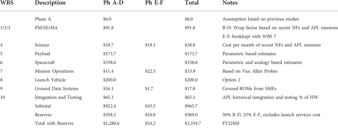
TABLE 4. Estimated Phases A-F MIO baseline mission cost by Level 2 work breakdown structure (WBS) element in Fy22$M.
Mission costs are reported in Table 4 using the level-2 (and level-3 where appropriate) work breakdown structure (WBS) provided in NPR (NASA Procedural Requrements) 7120.5F. The NASA New Start inflation index was used to adjust historical cost, price data, and parametric results to FY22 dollars if necessary. A launch vehicle cost estimate of $200 M is held in WBS 8, corresponding to Launch Vehicle Option 2 from the “Ground Rules for Mission Concept Studies in Support of Heliophysics Decadal Survey” [https://explorers.larc.nasa.gov] dated January 2022. A 44% cost to copy factor is applied to all copies of instruments and spacecraft (Whitley et al., 2013). Phase A–D cost reserves are calculated as 50% of the estimated costs of all components excluding the launch vehicle. Phase E–F cost reserves are calculated as 25% of the estimated costs of all Phase E elements excluding deep-sky network (DSN) aperture fees.
WBS 5 contains the Phase A-D costs for the mission payload. The instruments on the mother spacecraft were costed as $3.9 M for the FGM, $102.2 M for the Accelerator, $24.4 M for the Plasma Contactor, $10.3 M for the EDI, and $2.2 M for the EFW. For the 4 daughter spacecraft the 4 magnetometer instruments were costed at $6.1 M total, the 4 ESAs were costed at $7.0 M total, and 4 electronics boxes were costed at $4.3 M total. An 8.2% cost-to-cost factor was used in WBS 5 to estimate payload PM/SE/MA (program management/systems engineering/mission assurance) costs: the factor is based on the Van Allen Probes, New Horizon, MESSENGER, and Parker Solar Probe payload suite cost data with PM/SE/MA costs estimated as a percentage of the payload hardware. Technical management and systems engineering costs for individual instruments are carried in their respective instrument development costs.
There is technology development required for the Accelerator instrument prior to Phase A, and this development is estimated to be $27.1M–52.4 M FY22$. The main strategy for increasing TRL and reducing cost of the Accelerator will be to build a scaled down laboratory accelerator test stand consisting of a small number of Accelerator zones which would be sufficient for maturing key technologies [cf. Borovsky et al., 2022c].
A de-scope option is to remove the four daughter spacecraft and add two ESAs to the mother spacecraft. There are no changes to the launch vehicle assumption from the baseline mission. The same estimating methodologies for the baseline mission was applied to the de-scope option. The summary cost estimate with reserves for the de-scope goes from $1.335B to $999 M in FY22 dollars. In the de-scope option the ability to simultaneously measure radial and azimuthal gradients is lost: current generation mechanisms can be identified, but only poorly quantified. Hence the ability to satisfy Objective 4 of Section 3 is degraded in the de-scope.
A High-Level Mission Schedule was developed for MIO based upon the NASA Double Asteroid Redirection Test (DART), a mission of analogous scope and complexity for the main spacecraft. The four daughter spacecraft in MIO are less complex and are not expected to drive the MIO schedule. The Electron Accelerator is not currently at TRL 6: work will begin in Pre-Phase A to advance the TRL prior to PDR. All other instruments and spacecraft components are at TRL 6. The scheduling appears in Table 5. The scheduling is summarized as follows: Pre-Phase A (9 mos), Phase A Conceptual Design (12 mos), Phase B Preliminary Design (20 mos), Phase C Detailed Design (23 mos), Phase D Integration and Test (26 mos), Phase E/F Primary Mission Operations (24 mos). The Total Development Time Phase B-D (70 mos).
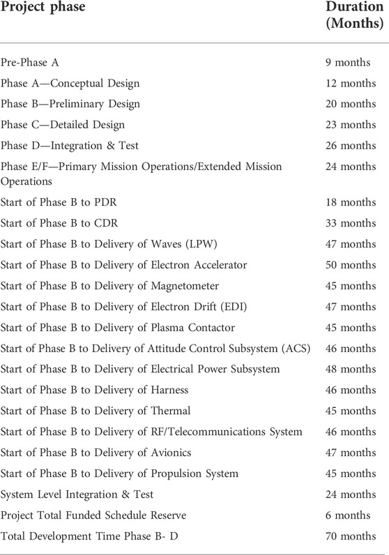
TABLE 5. Key phase duration table for the MIO mission concept.
Data availability statement
Publicly available datasets were analyzed in this study. This data can be found here: n/a.
Author contributions
JB (a) conceived of the MIO concept, (b) was the Principal Investigator for the NASA HMCS project, (c) led the MIO HMCS Science Team, and (d) helped to write this report. BB (a) led the JHU/APL Engineering Team that supplied the technical information in this report and (b) helped to write this report. MH (a) interfaced the MIO mission concept between the JHU/APL mission engineering and the LANL/SLAC accelerator-design work and (b) helped to write this report.
Funding
JB was supported at the Space Science Institute by the NASA Heliophysics Mission Concept Studies Program via award 80NSSC22K0113, by the NSF GEM Program via Grant AGS-2027569, and by the NASA HERMES Interdisciplinary Science Program via Grant 80NSSC21K1406.
Acknowledgments
The authors thank the members of the MIO HMCS Engineering Team listed in Table 2 and the members of the MIO HMCS Science Team listed in Table 3, particularly Gian Luca Delzanno, Eric Donovan, Brian Gilchrist, Mike Henderson, Larry Kepko, Bob Marshall, Vadim Roytershteyn, Emma Spanswick, Maria Usanova, and Simon Wing. The authors also thank Matthew Argall, Bob Ergun, George Hospodarsky, Omar Leon, Jonathan Van Noord, and Kateryna Yakymenko for their help.
Conflict of interest
The authors declare that the research was conducted in the absence of any commercial or financial relationships that could be construed as a potential conflict of interest.
Publisher’s note
All claims expressed in this article are solely those of the authors and do not necessarily represent those of their affiliated organizations, or those of the publisher, the editors and the reviewers. Any product that may be evaluated in this article, or claim that may be made by its manufacturer, is not guaranteed or endorsed by the publisher.
References
Anderson, B. J., Acuna, M. H., Lohr, D. A., Scheifele, J., Raval, A., Korth, H., et al. (2007). The magnetometer instrument on MESSENGER. Space Sci. Rev. 131, 417–450. doi:10.1007/s11214-007-9246-7
Andersson, L., Ergun, R. E., Delory, G. T., Eriksson, A., Westfall, J., Reed, H., et al. (2015). The Langmuir Probe and waves (LPW) instrument for MAVEN. Space Sci. Rev. 195, 173–198. doi:10.1007/s11214-015-0194-3
Atkinson, G. (1978). Review of auroral currents and auroral arcs. J. Geomagn. Geoelec. 30, 435–447. doi:10.5636/jgg.30.435
Borovsky, J. E. (1993). Auroral arc thicknesses as predicted by various theories. J. Geophys. Res. 98, 6101–6138. doi:10.1029/92ja02242
Borovsky, J., Bauer, B., Delzanno, G. L., Henderson, M., Holloway, M., Kepko, L., et al. (2022c). MIO magnetosphere-ionosphere observatory. Bull. Amer. Astron. Soc. in press.
Borovsky, J. E., Birn, J., Echim, M. M., Fujita, S., Lysak, R. L., Knudsen, D. J., et al. (2020a). Quiescent discrete auroral arcs: A review of magnetospheric generator mechanisms. Space Sci. Rev. 216, 1. doi:10.1007/s11214-019-0619-5
Borovsky, J. E., Delzanno, G. L., Dors, E. E., Thomsen, M. F., Sanchez, E. R., Henderson, M. G., et al. (2020b). Solving the auroral-arc-generator question by using an electron beam to unambiguously connect critical magnetospheric measurements to auroral images. J. Atmos. Sol. Terr. Phys. 206:105310, doi.org/doi:10.1016/j.jastp.2020.105310
Borovsky, J. E., Delzanno, G. L., and Henderson, M. G. (2020c). A mission concept to determine the magnetospheric causes of aurora. Front. Astron. Space Sci. 7, 595292. doi:10.3389/fspas.2020.595929
Borovsky, J. E., Delzanno, G. L., and Yakymenkno, K. N. (2022b). Pitch-angle diffusion in the Earth’s magnetosphere organized by the Mozer-transformed coordinate system. Front. Astron. Space Sci. 9, 810792. doi:10.3389/fspas.2022.810792
Borovsky, J. E. (2022a). Loss-cone-shift maps for the Earth’s magnetosphere. Front. Astron. Space Sci. 9, 944169. doi:10.3389/fspas.2022.944169
Borovsky, J. E. (2002). The magnetosphere-ionosphere observatory (MIO). Los Alamos National Laboratory Available at: https://www.lanl.gov/csse/MIOwriteup.pdf.
Borovsky, J. E. (2022b). The missing connections in the magnetosphere-ionosphere-thermosphere system: The science motivation for the HMCS magnetosphere-ionosphere observatory. Bull. Amer. Astron. Soc. in press.
Borovsky, J. E., and Valdivia, J. A. (2018). The Earth’s magnetosphere: A systems science overview and assessment. Surv. Geophys. 39, 817–859. doi:10.1007/s10712-018-9487-x
Borovsky, J. E., Yakymenko, K. N., and Delzanno, G. L. (2022a). Modification of the loss cone for energetic particles in the Earth’s inner magnetosphere. J. Geophys. Res. 123, e2021JA030106.
Delzanno, G. L., Borovsky, J. E., Thomsen, M. F., Gilchrist, B. E., and Sanchez, E. (2016). Can an electron gun solve the outstanding problem of magnetosphere-ionosphere connectivity? JGR. Space Phys. 121, 6769–6773. doi:10.1002/2016ja022728
Delzanno, G. L., Borovsky, J. E., Thomsen, M. F., and Moulton, J. D. (2015a). Future beam experiments in the magnetosphere with plasma contactors: The electron collection and ion emission routes. JGR. Space Phys. 120, 3588–3602. doi:10.1002/2014ja020683
Delzanno, G. L., Borovsky, J. E., Thomsen, M. F., Moulton, J. D., and MacDonald, E. A. (2015b). Beam experiments in the magnetosphere: How do we get the charge off the spacecraft? JGR. Space Phys. 120, 3647–3664. doi:10.1002/2014ja020608
Falthammar, C.-G. (1977). Problems related to macroscopic electric fields in the magnetosphere. Rev. Geophys. 15, 457. doi:10.1029/rg015i004p00457
Haerendel, G. (2011). Six auroral generators: A review. J. Geophys. Res. 116, A00K05. doi:10.1029/2010ja016425
Hearendel, G. (2022). My dealings with the aurora borealis. Front. Astron. Space Sci. 9, 1033542. doi:10.3389/fspas.2022.1033542
Il’in, V. D., Kuznetsov, S. N., Yushkov, B. Y., and Il’in, I. V. (1992). Quasiadiabatic model of charged-particle motion in a dipole magnetic confinement system under conditions of dynamic chaos. JETP Lett. 55, 645.
Il’ina, a. N., Il’in, V. D., Kuznetsov, S. N., Ysushkov, B. Y., Amirkhanov, I. V., and Il’in, I. V. (1993). Model of nonadiablatic charged particle mostion in the field of a magnetic dipols. JETP 77, 246.
Kurth, W. S., Hospodarsky, G. B., Kirchner, D. L., Mokrzycki, B. T., Averkamp, T. F., Robison, W. T., et al. (2017). The Juno waves investigation. Space Sci. Rev. 213, 347–392. doi:10.1007/s11214-017-0396-y
Lewellen, J. W., Buechler, C. B., Carlsten, B. F., Dale, G. E., Holloway, M. A., Patrick, D., et al. (2019). Space borne electron accelerator design. Front. Astron. Space Sci. 6, 35. doi:10.3389/fspas.2019.00035
Lucco Castello, F., Delzanno, G. L., Borovsky, J. E., Miars, G., Leon, O., and Gilchrist, B. E. (2018). Spacecraft-charging mitigation of a high-power electron beam emitted by a magnetospheric spacecraft: Simple theoretical model for the transient of the spacecraft potential. J. Geophys. Res. Space Phys. 123, 6424–6442. doi:10.1029/2017ja024926
Marshall, R. A., Xu, W., Kero, A., Kabirzadeh, R., and Sanchez, E. (2019). Atmospheric effects of a relativistic electron beam injected from above: Chemistry, electrodynamics, and radio scattering. Front. Astron. Space Sci. 6, 6. doi:10.3389/fspas.2019.00006
McFadden, J. P., Carlson, C. W., Larson, D., Ludlam, M., Abiad, R., Elliott, B., et al. (2008). The THEMIS ESA plasma instrument and in-flight calibration. Space Sci. Rev. 141, 277–302. doi:10.1007/s11214-008-9440-2
McNutt, R. L., Rieder, R. J., Keneshea, T. J., LePage, A. J., Rappaport, S. A., and Pualsen, D. E. (1995). Energy deposition in the upper atmosphere in the EXCEDE III experiment. Adv. Space Res. 15 (12), 13–16. doi:10.1016/0273-1177(95)00002-v
Mende, S. B. (2016a). Observing the magnetosphere through global auroral imaging: 2. Observing techniques. J. Geophys. Res. Space Phys. 121, 10623. doi:10.1002/2016ja022607
Mende, S. B. (2016b). Observing the magnetosphere through global auroral imaging: 2. Observing techniques. J. Geophys. Res. Space Phys. 121, 10638. doi:10.1002/2016ja022607
Mozer, F. S. (1966). Proton trajectories in the radiation belts. J. Geophys. Res. 71, 2701–2708. doi:10.1029/jz071i011p02701
National Research Council (2013). “Magnetosphere-to-ionosphere field-line tracing technology,” in Solar and space physics: A science for a technological society (Washington, D. C: Library of Congress 2013940083National Academies Press), 333–334.
Nishimura, Y., Bortnik, J., Li, W., Thorne, R. M., Lyons, L. R., Angelopoulos, V., et al. (2011). Estimation of magnetic field mapping accuracy using the pulsating aurora-chorus connection. Geophys. Res. Lett. 38, L14110. doi:10.1029/2011gl048281
Ober, D. M., Maynard, N. C., Burke, W. J., Moen, J., Egeland, A., Sandhold, P. E., et al. (2000). Mapping prenoon auroral structures to the magnetosphere. J. Geophys. Res. 105, 27519–27530. doi:10.1029/2000ja000009
O’Neil, R. R., Shepherd, O., Reidy, W. P., Carpenter, J. W., Davis, T. N., Newell, D., et al. (1978). Excede 2 test, an artificial auroral experiment: Ground-based optical measurements. J. Geophys. Res. 83, 3281–3288. doi:10.1029/ja083ia07p03281
Paschmann, G., Haaland, S., and Treumann, R. (2002). Auroral plasma physics. Space Sci. Rev. 104, 1.
Porazik, P., Johnson, J. R., Kaganovich, I., and Sanchez, E. (2014). Modification of the loss cone for energetic particles. Geophys. Res. Lett. 41, 8107–8113. doi:10.1002/2014gl061869
Prech, L., Nemecek, Z., Safrankova, J., and Omar, A. (2002). Actively produced high-energy electron bursts within the magnetosphere: The APEX project. Ann. Geophys. 20, 1529–1538. doi:10.5194/angeo-20-1529-2002
Prech, L., Nemecek, Z., Safrankova, J., Simunek, J., Truhlik, V., and Shutte, N. M. (1995). Response of the electron energy distribution to an artificially emitted electron beam: APEX experiment. Adv. Space Res. 15 (12), 33–36. doi:10.1016/0273-1177(95)00007-2
Prech, L., Ruzhin, Y. Y., Dokukin, V. S., Nemecek, Z., and Safrankova, J. (2018). Overview of APEX project results. Front. Astron. Space Sci. 5, 46. doi:10.3389/fspas.2018.00046
Raitt, W. J. (1995). Stimulating our piece of the universe: Active experiments in space. Rev. Geophys. 33, 559–564. doi:10.1029/95rg00102
Rapport, S. A., Rieder, R. J., Reidy, W. P., McNutt, R. L., Atkinson, J. J., and Paulsen, D. E. (1993). Remote x-ray measurements of the electron-beam from the EXCEDE-III experiment. J. Geophys. Res. 98, 19093–19098. doi:10.1029/93ja01154
Reeves, G. D., Delzanno, G. L., Fernandes, P. A., Yakymenko, K., Carlsten, B. E., Lewellen, J. W., et al. (2020). The Beam Plasma Interactions Experiment: An active experiment using pulsed electron beams. Front. Astron. Space Sci. 7, 23. doi:10.3389/fspas.2020.00023
Sanchez, E. R., Powis, A. T., Kagonovich, I. D., Marshall, R., Porazik, P., Johnson, J., et al. (2019). Relativistic particle beams as a resource to solve outstanding problems in space physics. Front. Astron. Space Sci. 6, 71. doi:10.3389/fspas.2019.00071
Shevchenko, I. G., Sergeev, V., Kubyshkina, M., Angelopoulos, V., Glassmeier, K. H., and Singer, H. J. (2010). Estimation of magnetosphere-ionosphere mapping accuracy using isotropy boundary and THEMIS observations. J. Geophys. Res. 115, A11206. doi:10.1029/2010ja015354
Smith, C. A., Edwards, R., and Whitley, S. (2021). APL’s spacecraft reliability performance. 2021 Annual Reliability and Maintainability Symposium, IEEE. 1–6. doi:10.1109/RAMS48097.2021.9605741
Spanswick, E., Donovan, E., Liang, J., Weatherwax, A. T., Skone, S., Hampton, D. L., et al. (2018). First-light observations from the transition region explorer (TREx) ground-based network. American Geophysical Union. Fall Meeting, abstract SM23B-04,2018AGUFMSM23B.04S.
Swift, D. W. (1978). Mechanisms for the discrete aurora -- A review. Space Sci. Rev. 22, 35. doi:10.1007/bf00215813
Thomsen, M. F., McComas, D. J., Reeves, G. D., and Weiss, L. A. (1996). An observational test of the Tsyganenko (T89a) model of the magnetospheric field. J. Geophys. Res. 101, 24827–24836. doi:10.1029/96ja02318
Torbert, R. B., Vaith, H., Granoff, M., Widholm, M., Gaidos, J. A., Briggs, B. H., et al. (2016). The electron drift instrument for MMS. Space Sci. Rev. 199, 283–305. doi:10.1007/s11214-015-0182-7
Tsyganenko, N. A. (1995). Modeling the Earth’s magnetospheric magnetic field confined within a realistic magnetopause. J. Geophys. Res. 100, 5599. doi:10.1029/94ja03193
Tsyganenko, N. A., and Stern, D. P. (1996). Modeling the global magnetic field of the large-scale Birkeland current systems. J. Geophys. Res. 101, 27187–27198. doi:10.1029/96ja02735
Weiss, L. A., Thomsen, M. F., Reeves, G. D., and McComas, D. J. (1997). An examination of the Tsyganenko (T89A) field model using a database of two-satellite magnetic conjunctions. J. Geophys. Res. 102, 4911–4918. doi:10.1029/96ja02876
Whitley, S., Hahn, M., and Powers, N. (2013). The incremental cost of one or more copies – quantifying efficiencies from building spacecraft and instrument constellations. Logan, UT: AIAA/Utah State University Small Satellite Conference. Available at: https://digitalcommons.usu.edu/cgi/viewcontent.cgi?article=2933&context=smallsat.
Winckler, J. R., Arnoldy, R. L., and Hendrickson, R. A. (1975). Echo 2: A study of electron beams injected into the high-latitude ionosphere from a large sounding rocket. J. Geophys. Res. 80, 2083–2088. doi:10.1029/ja080i016p02083
Keywords: aurora, magnetosphere, ionosphere, M-I coupling, electron beams, space experiments, earth system science
Citation: Borovsky JE, Bauer BA and Holloway M (2022) The magnetosphere-ionosphere observatory (MIO) mission concept. Front. Astron. Space Sci. 9:1052359. doi: 10.3389/fspas.2022.1052359
Received: 23 September 2022; Accepted: 27 October 2022;
Published: 10 November 2022.
Edited by:
Larry Lyons, University of California, Los Angeles, United StatesReviewed by:
Steve Milan, University of Leicester, United KingdomRobert Wilkes Ebert, Southwest Research Institute (SwRI), United States
Copyright © 2022 Borovsky, Bauer and Holloway. This is an open-access article distributed under the terms of the Creative Commons Attribution License (CC BY). The use, distribution or reproduction in other forums is permitted, provided the original author(s) and the copyright owner(s) are credited and that the original publication in this journal is cited, in accordance with accepted academic practice. No use, distribution or reproduction is permitted which does not comply with these terms.
*Correspondence: Joseph E. Borovsky, amJvcm92c2t5QHNwYWNlc2NpZW5jZS5vcmc=