 Jierong Liang*
 Cathrine D. Christiansen
 Kurt Engelbrecht
 Kaspar K. Nielsen
 Rasmus Bjørk
 Christian R. H. Bahl
- Department of Energy Conversion and Storage, Technical University of Denmark, Lyngby, Denmark
The efficiency of the magnetic refrigeration process strongly depends on the heat transfer performance of the regenerator. As a potential way to improve the heat transfer performance of a regenerator, the design of sub-millimeter hydraulic diameter porous structures is realized by freeze-cast structures. Four freeze-cast regenerators with different pore widths are characterized experimentally and numerically. Empirical parameters are determined for the correlations of heat transfer and flow resistance via a 1D model. Thermal effectiveness and pressure drop are measured for thermal-hydraulic evaluations. Temperature span and specific cooling capacity are obtained to compare the magnetocaloric potential based on the material La0.66Ca0.27Sr0.06Mn1.05O3. The stability of freeze-cast regenerators is validated by comparing the performance during, before and after oscillatory flow and periodic magnetic field tests. Smaller pore design obtain the better heat transfer performance and required mechanical strength, while pore design with significant dendrites provides the worst tradeoff between heat transfer performance and flow resistance.
Introduction
Magnetic refrigeration represents an environmentally friendly cooling technology with the potential for cost-saving operation, by using a solid refrigerant and using a thermodynamic cycle that can be more efficient than vapor compression cooling. The temperature change of a magnetocaloric material (MCM) in response to a changing magnetic field can be analog analog to the heating and the cooling of a gaseous medium in response to an adiabatic compression and expansion. The magneto-thermodynamic cycle named the active magnetic regenerator (AMR) cycle is commonly applied for prototypes in magnetic refrigeration (Barclay and Steyert, 1982; Kitanovski et al., 2015), due to the limited values of -isothermal entropy difference (ΔSiso) and adiabatic temperature change (ΔTad) in existing MCMs. As a core component in the AMR cycle, the regenerator undergoes: (1) adiabatic magnetization; (2) fluid flow from the cold to hot reservoir; (3) adiabatic demagnetization; and (4) reversed flow from the hot reservoir to the cold reservoir. AMRs, which perform as combined heat storage, heat exchanger and thermal energy generator, are moving closer to a possible commercialization, as they can lift the temperature span many times the adiabatic temperature change of the MCM (Kitanovski and Egolf, 2006; Kitanovski et al., 2015).
The MCM geometry is one of the critical factors that affects the AMR performance. The main reason is that a suitable porous structure of the MCM can effectively transfer the magnetic work to thermal energy at thermal reservoirs operating over a useful temperature span. Previous has focused on how the geometric parameters affect AMR performance. Lei et al. (2017) simulated and analyzed the regenerator performance with packed sphere beds, parallel plates, micro channels and packed wire screen geometries. This aimed at finding the optimal operating parameters. Li et al. (2019) tested and compared the performance of AMRs with gadolinium plates, spheres and flakes using a rotary magnetic refrigerator with the result that better cooling performance was obtained in the AMRs filled with flakes/spheres. Trevizoli et al. (2017) presented a systematic experimental evaluation of three AMRs with geometries of parallel-plate, pin array and packed sphere beds, based on approximately the same porosity and specific surface area; the AMR with packed spheres obtained the highest cooling capacity.
Packed bed regenerators are the most widely used geometry in AMRs due to their high cooling performance and easy fabrication. The reasons that other geometries such as parallel plates or mini-channels cannot easily replace the packed beds are: (1) thin walls are needed to facilitate heat conduction from the interior to the surface of MCM due to finite heat transfer (Nielsen and Engelbrecht, 2012); (2) thin walls are difficult to fabricate due to insufficient mechanical strength in MCMs (Nielsen et al., 2014; Tušek et al., 2014; Monfared and Palm, 2018); (3) high thermal performance requires small flow channel thickness, which can be difficult to manufacture consistently (Nielsen et al., 2013). The porosity of the MCM should not be too high in order to ensure the mechanical strength and energy generation density of the regenerator. Consequently, thin wall geometry results in a small hydraulic diameter and thus high flow resistance.
Freeze-casting is an environmentally friendly materials processing route (Deville, 2008), which freezes a suspension of material particles and solvent (normally water). During the solidification process, ice dendrites grow and particles concentrate within the space between the ice dendrites, forming channels of nearly pure ice surrounded by particles. After the ice is removed by freeze drying, micro-channels remain. The freeze-casting technique is intrinsically flexible to tune the pore characteristics within a certain range (Fukasawa et al., 2001; Naviroj et al., 2017; Scotti and Dunand, 2018). From our tuning abilities at the Technical University of Denmark (DTU), the pore size can be tuned by changing suspension characteristics and solidification conditions (Christiansen et al., 2018, 2019, 2020a). Generally, each regenerator is most efficient over a specific domain of operating conditions, which depends itself on geometrical parameters. To achieve a more in-depth investigation of freeze-cast regenerators, this study focuses on identifying the proper pore size and the corresponding operating conditions. A freeze-cast regenerator identified as having small hydraulic diameter and which may be manufactured with thin walls, was preliminarily studied previously (Liang et al., 2020), with focus on the heat transfer potential of freeze-casting ceramics applied in a passive regenerator. From zero applied field test of a single sample, the main advantage of the freeze-cast regenerator is the excellent heat transfer performance due to the small hydraulic diameter and large specific surface area. However, the flow resistance is larger than in packed bed regenerators. Thus, more samples with different morphologies are valuable to further assess the potential of freeze-cast regenerators.
No experimental or modeling data about freeze-casted structures as AMRs in a time-varying magnetic field has previously been published. Active characterization using a linear AMR test machine (Bahl et al., 2008) is a small-scale and simplified way to study the performance of freeze-cast regenerators with different geometry parameters. Temperature span and cooling capacity are the most common performance indicators in active characterizations (Paulo Vinicius Trevizoli, 2015). In the active mode, the performance is strongly related to the magnetocaloric effect (MCE) of the material, operating conditions (utilization and frequency), and intrinsic geometry parameters (porosity, specific surface area and pore size) (Tušek et al., 2013). The MCM in the freeze-cast regenerator studied in this work is La0.66Ca0.27Sr0.06Mn1.05O3 (LCSM06), which is identified as one of the magnetocaloric ceramics [La0.66Ca0.33−xSrxMn1.05O3, LCSMx (Dinesen et al., 2005)] with a second order phase transition (SOPT). LCSMx ceramics are attractive alternatives to the benchmark material gadolinium (Gd) due to similar specific isothermal entropy difference (Δsiso) during (de)magnetization (Dinesen, 2004), adjustable transition temperature, corrosion resistant and less expensive compounds. Bahl et al. (Bahl et al., 2012) experimentally extrapolated the maximum zero-span cooling capacity, which is significantly larger than the highest measured value for Gd plates in the similar tests. For the purposes of easy fabrication and mechanical stability, LCSMx is one of the best choices to freeze-cast the first generation regenerator. The freeze-casting process is flexible regarding material choice, where both metals (Chino and Dunand, 2008; Cuba Ramos and Dunand, 2012), ceramics (Fukasawa et al., 2001; Deville, 2008; Naviroj et al., 2017; Christiansen et al., 2018, 2019, 2020a; Scotti and Dunand, 2018), polymers (Zhang et al., 2005; Arai and Faber, 2019) and composites of the three (Zhang et al., 2005; Vickery et al., 2009) have successfully been shaped by this processing route. It can be assumed that other MCMs are compatible with freeze-casting. However, comparing the AMR performance of different freeze-cast regenerators based on the same MCM, is valuable to study the geometry effect on the conversion ability from magnetic work to thermal energy. The available performance metrics consist of cooling capacity, temperature lift, Coefficient of Performance (COP), exergetic power quotient (Griffith et al., 2019) and second law efficiency (Rowe, 2011).
In this paper, four freeze-cast regenerators are tested passively without magnetic field to investigate the heat transfer and flow resistance characteristics. Combined with the modeling modeling and fitting to the experimental data, correlations of Nusselt number and friction factor are determined. In the second step, active experiments of the same regenerators on a linear magnetocaloric test machine are carried out in order to evaluate the AMR performance. Finally, some of the passive and active experiments are repeated in order to validate the reproducibility and stability of the freeze-cast regenerators.
Regenerator Preparation and Geometric Characterization
Three regenerators (#1, #2 and #3, Figure 1) were fabricated by freeze-casting under similar conditions to our previous study on freeze-cast regenerators (regenerator #4) (Liang et al., 2020). A ceramic suspension for freeze-casting was prepared from 30 vol% of LCSM06 (CerPoTech, Norway) in MiliQ water with 2.5 wt%, solid to ceramic ratio, of dispersant (DURAMAX™ D-3005, Rohm and Haas, Dow Chemical, USA). PH was adjusted to ~7 by addition of 1M nitric acid in order to establish a sufficient dispersion of particles. The suspension was then homogenized for 72 h on a low energy ball mill. 2 wt%, solid to ceramic ratio, of binder (DURAMAX™ B-1022, Rohm and Haas, Dow Chemical, USA), was added and the suspension was mixed for a few hours. The suspension was de-aired in vacuum immediately before casting. During freeze-casting, the suspension of LCSM06 particles in water was frozen directionally by bringing one side of the suspension into contact with a cooling source. Here, we utilized a custom-built freeze-casting set-up with thermoelectric temperature control of the cooling source (Christiansen et al., 2020b). The temperature of the cooling source is decreased by −0.5, −1.5 and −2.5 K/min (regenerators #1 to #3, respectively) and the arising thermal gradient causes ice crystals to grow along the gradient direction, pushing aside particles, causing these to segregate, which results in a two phase structure of ice crystals along the thermal gradient and segregated ceramic particles. The ice was removed by sublimation in a freeze-drier and the green bodies were sintered at 1100 °C for 12 h, resulting in porous ceramic structures with well-defined microchannels where the ice used to be. The size of the ice crystals during freeze-casting, and thereby the size of the resulting micro-channels in the fired ceramic, depends on the freezing conditions; where faster cooling rates results in smaller channels (Christiansen et al., 2020b). Here, only the freezing rates were varied in order to achieve a range of pore widths enabling the study of the influence of pore width on AMR performance. The three new regenerators are compared with our previously published regenerator (#4), and all the geometrical parameters are summarized in Table 1. The structural features of the freeze-cast regenerators were characterized by image analysis of micrographs, as described in detail in previous studies (Liang et al., 2020). Micrographs were obtained using a scanning electron microscope (TM3000, Hitachi High-Technologies). For each sample 12 micrographs, covering an area of 3310 × 2483 μm each, in the perpendicular cross section, obtained evenly distributed across the cross sections, were analyzed. Pore width, macro porosity, specific surface area and tortuosity were evaluated based on image analysis. The mean and standard deviation of all parameters are listed in Table 1. From the regenerators with small pore width to large pore width (Figures 1A–D), the aspect ratio of cross sectional pore shape increases. That means the freeze cast regenerators with the small pore width are prone to have narrow channels.
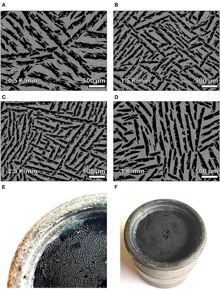
Figure 1. Geometry of freeze-cast regenerators. Scanning electron microscopy (SEM) micrographs of cross sections of the freeze-cast samples from regenerators #1 (A), #2 (B), #3 (C) and #4 (D), where gray areas are the ceramic walls and black areas voids in the form of aligned, lamellar channels. Micrographs were obtained at cross sections parallel to the freezing direction in the center of the structure. Photographs of regenerator #1 (E,F) after mounting the samples into the housing. A single freeze-cast regenerator matrix consists of two combined monolithic pieces of freeze-cast samples frozen at identical conditions and thus with homogenous structural characteristics. Other SEM images at different positions are available at Supplementary Presentation 1.
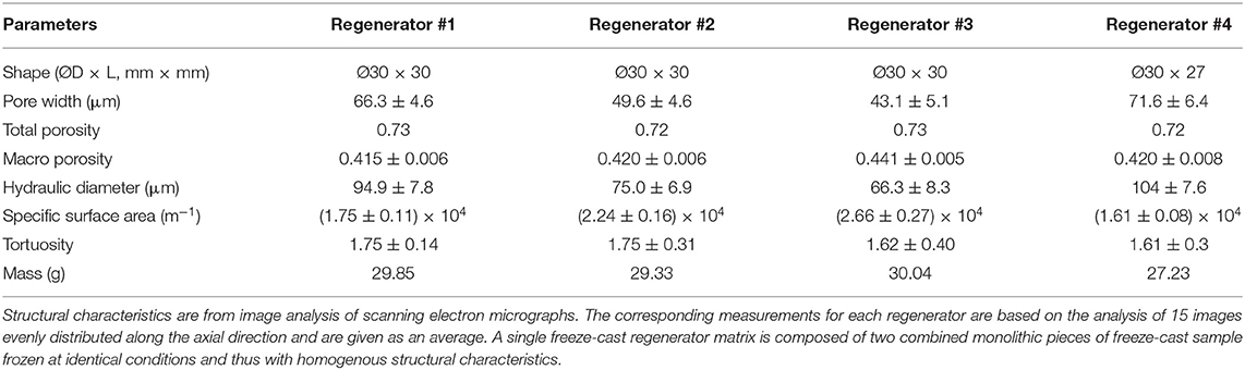
Table 1. Geometrical parameters of the freeze-cast regenerators.
As freeze-casting is very sensitive to apparent conditions complicating the reproducibility of freeze-casts across different suspension batches, set-ups, furnace conditions etc. (Naleway et al., 2016), regenerators #1-3 were fabricated from the same batch, frozen subsequently and dried and sintered together. Accordingly, regenerator #1-3 exhibits a larger degree of dendrites obstructing the channels than regenerator #4, which was fabricated from a different batch and with much smoother channel walls. Therefore, the measured mean pore width of regenerator #4 in Table 1 is greater than that of #3 in spite of the earlier argument stating that faster freezing results in smaller channels.
In porous media, the pores can be interconnected, dead end or isolated (Kaviany, 1995). The total void volume divided by the total volume occupied by the solid matrix and void volumes, is defined as the total porosity, or sample porosity (ε) in this study. However, the fluid only flows through the interconnected pores. The volume fraction of the interconnected pores is defined as the effective porosity or macro porosity (εm), which is derived from image analysis. As seen from Table 1, the macro porosity is about 2/3 of the total porosity. Thus, the dead end pores are assumed negligible. The remaining porosity can be treated as micro porosity in the walls. In this study, εm is used for determining pore velocity while ε is adopted for solid mass calculations. Additionally, the hydraulic diameter (Dh) and tortuosity (𝔗) are derived as follows:
where α is the specific surface area derived from image analysis, Lpore is the average pore length, and Lr is the length of the regenerator sample.
Experiment and Modeling
The experimental investigation was performed both on a passive rig (Lei, 2016) and active magnetocaloric test machine (Navickait et al., 2018) at DTU. The device configurations are discussed elsewhere (Lei et al., 2018), but the overall experiment program and the simplified diagram of the test device with the key measurements are given in Figure 2. The hydraulic flow profile in the passive rig and the synchronization of flow profile and magnetic field in the active machine are shown in Figure 3.
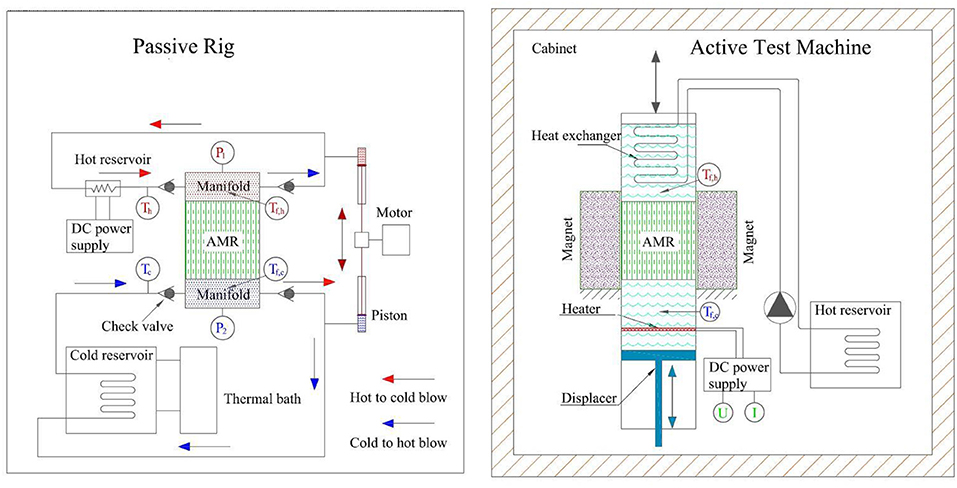
Figure 2. Schematic diagram of passive rig and AMR test machine. The passive rig consists of the regenerator, manifolds, cold and hot reservoirs, piston and motor assembly, and check valves. The manifolds are situated at the ends of the regenerator, which incorporates the type E thermocouples (Omega) and pressure transducers (Gems). The thermocouples for measuring Tf,h(t) or Tf,c(t) are positioned at the center of the cross section between the regenerator and manifoldTf,h(t)Tf,c(t)Tf,c(t). The outflow from the manifold goes through the outlet check valve, piston, cold reservoir or heater, inlet check valve, and then back to the inlet of the manifold. The test machine, which is situated in a temperature-controlled cabinet, consists of a stationary Halbach array permanent magnet, a movable regenerator, a piston for displacing fluid, and hot and cold reservoirs. The temperature of the hot reservoir is regulated by a heat exchanger interacting with the ambient in a cabinet. The heat load in the cold reservoir is simulated by a resistance heater. The whole experiment procedure goes through: (1) passive test with different operating parameters; (2) passive test with different manifolds; (3) repetition of passive experiments; (4) active test; and (5) repetition of passive experiments.
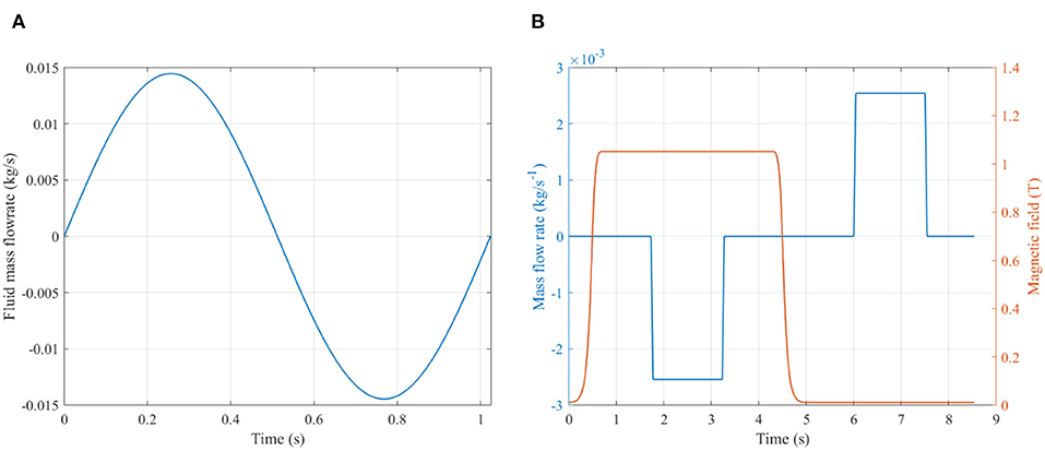
Figure 3. Time evolution of (A) the fluid mass flow rate in passive rig and (B) the synchronized magnetic field and fluid mass flow rate in active test machine during the different steps of over one magnetic cycle. Since the passive rig and AMR test machine run at different frequencies, the amplitudes of fluid mass flow rate are significantly different between passive and active characterizations.
Passive Characterization
Since the passive rig is essentially a synchronized AMR device with zero magnetic field, a comparative study of freeze-cast regenerators in terms of heat transfer performance and flow resistance can be addressed here. In the passive rig, the regenerator is subjected to an oscillatory flow in steady state with constant reservoir temperatures. The regenerator is treated as a thermal storage heat exchanger subjected to intermittent alternating heat transfer facilitates between the solid matrix and the fluid in two periods: (1) hot blow: fluid from the high-temperature reservoir warms up the solid matrix; (2) cold blow: reversing the fluid flow and the matrix releases the stored heat. The information from temperature and pressure measurements is further processed to obtain the thermodynamic indicators. The predefined operating parameters consist of motor frequency (f), piston stroke (Sp) and piston cross sectional area (Ac,p). Thermo-hydraulic parameters such as utilization (U) and Reynolds number (Reh) link to the operating conditions through:
Where ρf, cf and uf are the density, specific heat capacity and dynamic viscosity of the fluid, respectively. The subscripts f and s denote solid and fluid phases, respectively. Note that the solid specific heat capacity cs is strongly temperature dependent with a peak near the transition temperature. Here we use the background value rather than the peak value. The Reynolds number based on the pore velocity and hydraulic diameter Reh is selected to be consistent with the previous form of the correlations (Jiang et al., 2001). Ac,p and Ac,r are the cross sectional areas of the piston and the regenerator, respectively. vf is the superficial velocity in the regenerator, which is a hypothetical flow velocity disregarding the skeleton of the porous medium. vp is the moving velocity of the piston, its sinusoidal profile is determined by the crank motion in the passive rig.
The measurements for performance metrics are end pressure profiles [p1(t) and p2(t)], end temperature profiles [Tf,h(t) and Tf,c(t)] and reservoir temperatures (Th and Tc). The heat transfer performance and flow resistance can be characterized by the Nusselt number (Nu), number of transfer unit (NTU), effectiveness (ηh and ηc) and friction factor (Choi et al., 2004) (fosc).
Here h is the interstitial solid-fluid heat transfer, which is derived from modeling and fitting. The terms kf, α, Vr and Lr are fluid thermal conductivity, specific surface area, volume and length of regenerator, respectively. In the NTU approximation (Equation 7), constant fluid properties are assumed due to the weak temperature dependence on density and specific heat capacity in pure water. ηh and ηc are effectivenesses associated to hot blow and cold blow. The approximations in Equation (8, 9) eliminate the effect of possible mismatching phases of Tf,h, Tf,c and ṁf during the measurements. The parameter fosc is the oscillatory friction factor based on the maximum pressure drop consistent with the correlations.
Through the passive experiments, Nu and fosc have been correlated through model fitting based on a single regenerator previously reported (Liang et al., 2020). The parameters in the correlations are further validated by variable geometrical parameters, such as the pore size. The correlations in Nu and fosc are taken from our previous study based on the regenerator #4.
Where c1 ~ c4 are fitting parameters assumed to depend on matrix morphology only; Pr is the Prandtl number.
Active Characterization
The AMR test machine is a small-scale reciprocating system (Figure 2), which consists of a fixed Halbach cylinder permanent magnet and a reciprocating regenerator. The apparatus performs a four-step AMR cycle; the applied magnetic field is changed periodically from ~0 to 1.1 T. Oscillatory fluid blows are generated by the piston synchronizing with the magnetic field changing. The period for each of the four steps cycle are controlled by the stepper motors, and marked (τ1-τ4) in Figure 3A. Thus, the frequency in the AMR test machine is determined by:
Where τ and τ1- τ4 are the whole cycle period and the each step period, respectively. During the blow periods (τ2 and τ4), the flow profile is divided into parts taken up by flow pauses, flow ramps and full flow, all together add up to one for a complete cycle.
An electric heater works as a cooling load simulator at the cold end, of which power is determined by the product of voltage and current. The specific cooling capacity is defined as
Where Uheater and Iheater are voltage and current respectively. As a compact design to reduce the dead volume effect (Trevizoli et al., 2018), the thermocouples located at the hot end (Tf,h(t)) and cold end (Tf,c(t)), which are shown in Figure 2, are only used for reservoir temperature estimations.
Where ΔT is the temperature span. The whole apparatus is installed in a thermostatically controlled cabinet. The temperature Th is controlled by adjusting the cabinet temperature due to heat interaction between the cabinet and heat exchanger. The temperature equilibrium between the hot reservoir and ambient is determined in part by heat leakage to the cabinet, which are minimized in the experimental setup. Although the system still must accept a small heat leak that deteriorates the performance, it is also a realistic operating condition for a real magnetic refrigeration application (Arnold et al., 2014). The temperature evolution speed is observed to decrease with time as the system stabilizes. The cyclic steady state point is treated as a cutoff criterion for evaluating the performance (Czernuszewicz et al., 2019), including Equation (14–17). In the community of magnetic refrigeration, curves of cooling capacity () vs. temperature span (ΔT) are usually defined as the cooling curves (Rowe, 2011). In general, the slope of the cooling curves is steeper in higher utilization conditions (Trevizoli et al., 2016; Li et al., 2019). At the end-points of cooling curve are zero-span cooling capacity and no-load temperature span, which are essential metrics in AMR devices (Teyber, 2018).
Results and Discussions
Freeze-cast regenerators #1, #2 and #3 are compared experimentally in order to investigate the flow resistance, heat transfer performance, cooling capacity, regenerative temperature lift and mechanical stability. Relevant data regarding regenerator #4 may be found in our previous study (Liang et al., 2020).
Modeling Correlations and Validation
The fitting parameters in Equation (11, 12) determined for each regenerator are shown in Table 2. The values of c1 and c2 are varied by different pore sizes, especially in regenerator #3 (the smallest pore size). The values of c3 and c4 are treated as constants because of negligible changes during the fitting program.

Table 2. The values of the correlation parameters by fitting program, c3 and c4 of regenerators #1 to #3 are treated as the same as the values in regenerator #4, because the deviations between the modeling and experiments are small.
The deviations between experiment and the fit in Tf,h(t), Tf,c(t) and pressure drop are evaluated by the relative root mean square error (RRMSE) under all tested operating conditions and regenerators #1, and #2 and #3 in Figure 4. Comparing the fit and experimental data, the maximum temperature deviation is 1.18 and 3.6% for pressure drop, which indicates that the simulation results are in good agreement with the experimental readings and thus that the parameters in Table 2 can be used to model the internal characteristics of the freeze-cast regenerators.
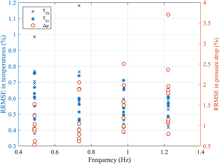
Figure 4. Experimental and fit comparisons of relationships of RMSE distributions for regenerators #1, #2 and #3.
Passive Performance Analysis
Pressure drop is the major characteristic of the flow resistance in a regenerator. The pressure drop generally depends on pore velocity, regenerator length, hydraulic diameter, channel tortuosity and channel wall roughness. Since the tested regenerators are designed with the same length, tortuosity, macro porosity, total porosity and surface roughness, the curves of Δpmax ~ f in Figure 5A are essentially the relations of the pressure drop and the pore velocity. As found in literature (Lei, 2016), the frequency and therefore the velocity responds quite linearly to the pressure gradient, which suggests that Darcy's law is valid for these regenerators. These phenomena are widely captured for small amplitude oscillating flows (Hsu et al., 1999; Hsu and Biwa, 2017). The oscillatory flow pressure loss increases both with increasing dimensionless oscillation amplitude () and kinetic Reynolds number (Zhao and Cheng, 1996). Consequently, a smaller hydraulic diameter results in a higher pressure drop, based on the same flow conditions and other geometry parameters. The pressure drops in regenerators #1, #2 and #4 are similar. As will be discussed below, regenerator #1 shows higher pressure drop than expected based on the hydraulic diameter in Table 1. One possible reason from Figure 1A is more dendrites in regenerator #1, which results in higher roughness and hydraulic resistance.
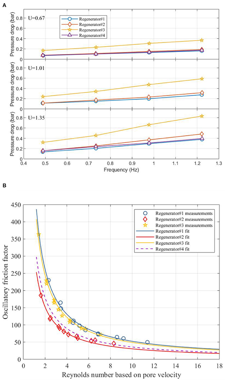
Figure 5. (A) Pressure drop amplitude as a function of frequency and (B) oscillatory friction factor as a function of pore Reynolds number under different utilizations. All the regenerators are measured based on the same manifold and hydraulic system in the passive rig. All the regenerators have nearly the same sample porosity, macro porosity and shape. Note that there is ~10% reduction of the length of regenerator #4 due to practical reasons. The data for regenerator #4 are derived from Liang et al. (2020).
The dimensionless relationships of fosc ~ Reh are shown in Figure 5B. Because the variations in hydraulic diameter between the regenerators, the fosc in regenerators #1 and #3 are close to each other, while the fosc in regenerator #2 is lower. The friction factor in the pores for periodic steady flows can be generally defined as follows (Zhao and Cheng, 1996; Jin and Leong, 2008; Pamuk and Özdemir, 2012).
Where Dr is the inner diameter of the regenerator. K is the permeability of the porous media, which links to the pore structure as K ∝ (c, ε, 〈r〉2) (Nishiyama and Yokoyama, 2017). The geometric factor c is related to the shape, connectivity, aspect ratio and tortuosity of the pores. Average pore radius 〈r〉 indicates the pore width. F is the inertial coefficient, which is normally important when the flow velocity is high. Consequently, parameters c1 and c2, which correspond to Equation 11 and Table 2, indicate the viscous and inertial forces, respectively. For low velocity the viscous term dominates, whereas for high velocity the inertia term does. Since the Reh is quite low (<15), the corresponding low value of c2 represents the weak inertial behavior in freeze-cast regenerators. Intrinsically the friction factor is mainly determined by the permeability. According to Figure 1, when the pore width decreases, the cross sectional shape of pores becomes narrow; the permeability might be reduced. However, in regenerator #3 with large pore size, dendrites are obvious inside the pores; which also results in low permeability. Thus, the regenerator #2 have the highest permeability among these three regenerators due to the value of c1 in Table 2. From our tuning ability of pore width, there will be an optimal pore width obtaining the highest permeability and lowest hydraulic resistance, which needs detailed characterization of regenerators of various pore widths in the future.
Effectiveness is an index for heat storage evaluation. It depends on operating conditions (i.e., utilization and frequency), solid thermal conductivity and interstitial heat transfer performance. The ηh ~ NTU curves based on each utilization in Figure 6 reveal the comparison of interstitial heat transfer between different freeze-cast regenerators. In principal, the trends of ηh ~ NTU for freeze-cast regenerators should be a positive correlation. As discussed previously (Liang et al., 2020), thermal losses and equipment problems may cause negative correlations at some points (see Figure 6). Regenerator #3 exhibited the highest average effectiveness over NTU. This is probably attributed to the larger specific surface area shown in Table 1, and the higher interstitial heat transfer coefficient. Since the Nu correlations are the same among these freeze-cast regenerators (Table 2), smaller hydraulic diameter design results in higher heat transfer coefficient in Equation 5. For each utilization in regenerators #1 to #3, the average ηh and the hydraulic diameter of regenerator are also in positive correlation. Smaller pore width or hydraulic diameter will cause higher heat transfer performance based on the same operating condition and geometry parameters. Regenerator #4 has estimated 10% MCM loss due to necessary modification to mount the regenerator in the housing. Thus, the effectiveness in regenerator #4 is the lowest as the local utilization is higher than for the others. Therefore, processing freeze-cast regenerators with smaller pore width can improve heat transfer performance to some extent.
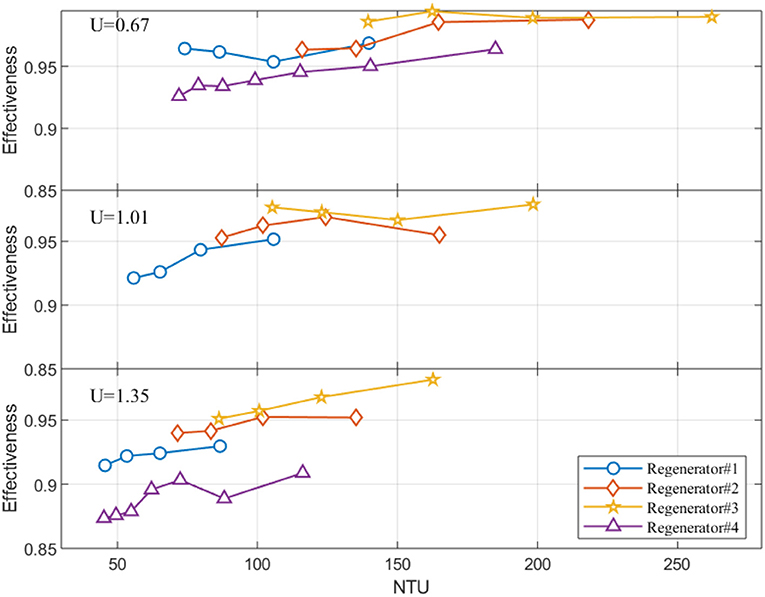
Figure 6. Effectiveness as a function of NTU for different utilizations. The effectiveness is based on hot to cold blow. Since there is ~10% reduction in length in regenerator #4, the actual utilization in regenerator #4 is higher than others at the same subplot. The data at regenerator #4 are from our previous publication (Liang et al., 2020).
To couple the heat transfer and flow resistance characteristics, the UA (heat transfer coefficient times heat transfer surface area) vs. pressure drop are plotted in Figure 7. UA increases with the pressure drop with a sub-linear trend. The improvement of UA caused by increasing pressure drop decreases when the value of UA is sufficiently large. Regenerator #1 exhibits the lowest values of heat transfer performance for a given pressure drop compared to other freeze-cast regenerators. The main reasons are probably the details of the channel shape such as significant dendrites (Figure 1A) and larger friction factor (Figure 4A). Consequently, the internal dendrites probably cannot significantly enhance heat transfer performance by imposing channel roughness. One way to achieve a better trade-off between heat transfer and flow resistance is reducing the dendrites, which should be considered in future processing of freeze-cast regenerators.
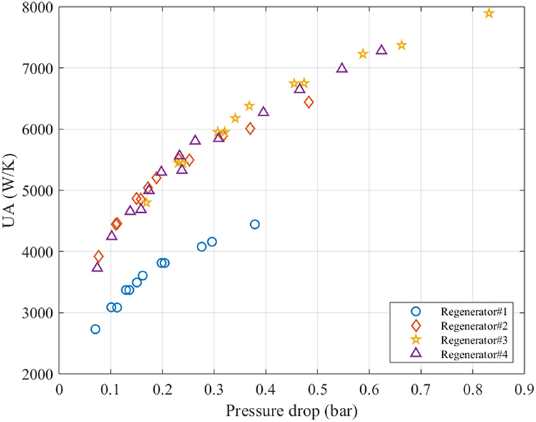
Figure 7. UA vs. pressure drop among regenerators #1, #2, #3 and #4.
Active Cooling Performance Comparison
Due to reasons described in section Regenerator Stability, only regenerators #3 and #4 were tested successfully in the active test machine. Since the mass of each regenerator is small (~30 g), the absolute values of the temperature span are small in comparison to other results from the same AMR device (Bahl et al., 2012; Turcaud et al., 2015). However, the results shown in Figure 8 are valid for comparable studies of the regenerators discussed here. Compared to relevant measures in Lei et al. (2015, 2018); Navickait et al. (2018) with first order phase transition (FOPT) materials, the no-load temperature span (ΔT0) in Figure 8A is not so sensitive to the hot reservoir temperature due to the weaker temperature dependency of LCSM06 properties. MCMs always show the largest performance around their transition temperature. The maximum ΔT0 for both regenerators #3 and #4 are located at . This reveals that the actual transition temperatures of LCSM06 in the freeze-cast regenerators are around 15oC. As regards the absolute value of ΔTad, LCSMx cannot compete with Gd. Engelbrecht et al. (2011) tested tape cast LCSMx plate regenerators, and obtained a maximum temperature span of 5.1°C, which was lower than the maximum temperature span in Gd. This was caused by higher specific heat capacity in LCSMx and therefore lower adiabatic temperature change(Δ Tad)
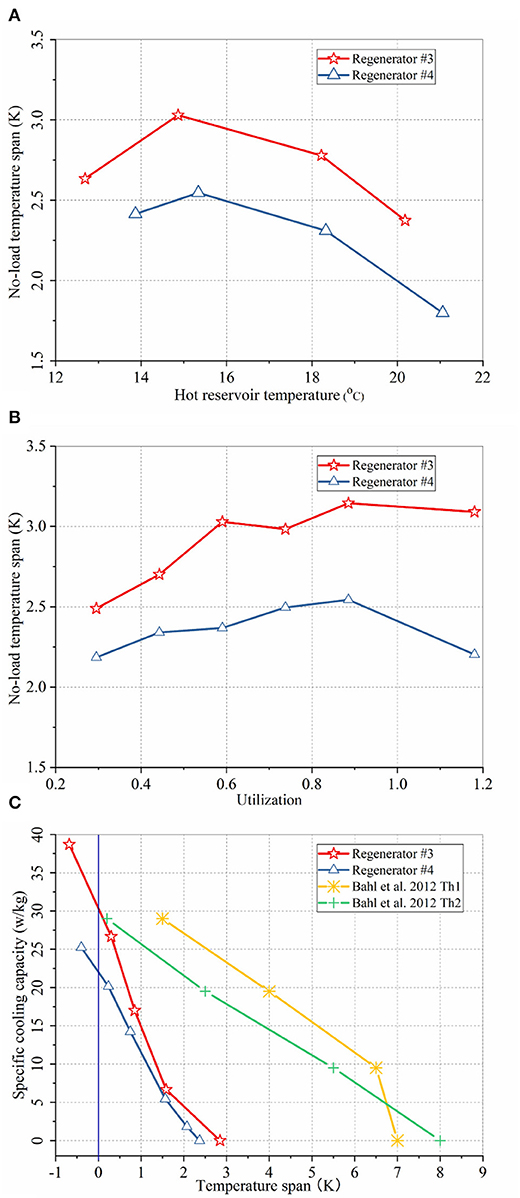
Figure 8. (A) Temperature span as a function of hot reservoir temperature at a utilization of 0.59 between regenerators #3 and #4. (B) Temperature span as a function of utilization at hot reservoir temperature of ~15°C between regenerators #3 and #4. (C) Specific cooling capacity vs. temperature span (cooling curves) at utilization of 0.59 and hot reservoir temperature of ~15°C between regenerator #3 and #4, and cooling curves from a parallel plate regenerator with similar MCM at utilization equals 0.5. Th1 and Th2 mean the hot reservoir temperatures are 8°C and 11°C, respectively. The MCM in parallel plate regenerator is layered by two LCSMx with different Curie temperatures, which the MCM in freeze-cast regenerators is LCSM of single layer.
Curves of ΔT0 ~ U presented in Figure 8B indicate the optimal utilizations are ~0.88 for both regenerators under no-load operations. In the active test machine, heat transfer to the ambient through the housing and piston are unavoidable. Since the amount of cooling capacity is small in freeze-cast regenerators, heat losses/gains are critical in the experiments. The optimum utilization is a balance between enough fluid being blown to maintain a high cooling capacity for covering the heat gain from the ambient, but at the same time little enough not to destroy the temperature span (Navickaite et al., 2018). Since cooling capacity in freeze-cast regenerators is rather weak, the proportion of the ambient heat gain made by cooling capacity is large. Thus, the optimum utilization here is larger than common values reported in literature (Paulo Vinicius Trevizoli, 2015). The temperature span measured is between 2.5 and 3.2 K due to too small MCM mass compared to the inherent losses in the machine. Furthermore, the ΔT0 is higher in regenerator # 3 than in regenerator #4, because of better heat transfer performance in regenerator #3.
The cooling curves of specific cooling capacity (, Equation 11) vs. ΔT are shown in Figure 8C. In the cooling curves of regenerators #3 and #4, the specific cooling capacities decrease proportionally to the temperature span, which are consistent with other cases where spatial variations in MCMs are negligible (Trevizoli et al., 2016). Since the performance metric considers the effect of MCM mass, the outperformance of cooling curves in regenerator #3 can be attributed to the excellent heat transfer performance contributions. Two cooling curves from Bahl et al. (2012) are introduced in Figure 8C, which are based on a graded two-layer regenerator, with two different LCSMx materials, in the form of stacked parallel plates. The MCM properties between the freeze-cast regenerators and the parallel plate regenerator are almost the same, except the different Curie temperatures. Additionally, despite being tested under the same operating conditions using the same experimental rig, the thermal isolations of regenerators vary due to different housing thicknesses. Thus, the comparisons are only to validate the active experiments rather than performance analysis. The MCM mass of regenerators in Bahl et al. (2012) is 51.1 g, comparing to 33.7 g in regenerator #3. Due to the mass difference and two-layer MCM in parallel plate regenerator, the no-load temperature span in freeze-cast regenerators are smaller than in parallel plate regenerator. The specific zero-span cooling capacity (ΔT = 0K) in regenerator #3 is quite close to this parallel plate regenerator. Thus, the results from active experiments can reasonably reveal the performance difference between freeze-cast regenerators #3 and #4 due to different heat transfer performance.
Regenerator Stability
The material stability and integrity are critical factors for future commercialization. The stability mainly depends on geometrical parameters (i.e., porosity and pore size), and process routine (i.e., sintering temperature and period). All the regenerators were run at least 200 h for the passive rig and 120 h for the active test machine. All the regenerators survived the passive testing. In Figures 9A,B, regenerator #1 results repeated during a passive measurement before the active test. Comparing the effectiveness and pressure drop between the initial and a reproducing test, almost no variation is found in terms of heat transfer performance and flow resistance. It is thus to some extent shown that the regenerators can withstand the oscillatory flow impacts. However, regenerator #1 did not survive more than about 96-h of active test; cracks were found at both ends. This means that the material cannot withstand the magnetic force during the reciprocating test for a long time. The reason is probably that a significant amount of MCM is in the form of dendrites inside the channels (Figure 1), thus reducing the effective form of the walls based on the fixed porosity. Due to an accidental issue, regenerator #2 was destroyed after passive testing and could not be run in the active test machine. Regenerators #3 and #4 successfully passed the passive and active tests without any visible wear. In Figure 9C, the passive test of regenerator #4 is repeated after all the passive and active tests finished. No significant changes in effectiveness are observed, which validates the material stability. The pressure drop decreases slightly, probably as a result from the fluid flow initially unclogging some channels, since some fine powder was captured in the meshes initially. However, after a few days of operation, no powder was visually observed. Similar results are also captured in regenerator #3, not presented here for brevity. Thus, all the freeze-cast regenerators can withstand oscillatory flow but the large pore design seems not to be suitable for periodic magnetic field conditions. Further assessment of freeze-cast regenerators is needed to identify processing parameters and corresponding structural features related to mechanical integrity under the specific operational conditions of an AMR.
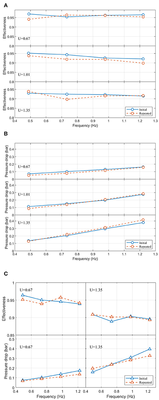
Figure 9. Effectiveness (A) and pressure drop amplitude (B) comparisons between initial test and repeated test under utilizations of 0.67, 1.01, and 1.35 in regenerator #1. The curve marked “repeated” stands for a repeated passive test after about 300 h of passive testing. (C) Effectiveness and pressure drop amplitude comparisons between initial test and repeated tests under utilizations of 0.67 and 1.35 in regenerator #4. The reproducing experiment was done after nearly 700 h of passive testing and 120 h of active testing.
Conclusion
Four unconventional microchannel regenerators with different pore widths were fabricated by freeze-casting via different processing temperature profiles. All the regenerators were thermally and hydraulically characterized. The effectiveness and friction factor were derived from the passive experiments, while the cooling capacity and temperature lift were obtained from the active test machine experiments. The experimental data were fitted to the correlations related to heat and mass transfer in a 1D model. The following performance features were obtained:
• Regenerator #2 with a pore width of 49.6 μm achieved the highest flow permeability within the tested freeze-cast regenerators.
• For freeze-cast regenerators a larger pore width results in a decrease of both heat transfer effectiveness and pressure drop.
• Regenerators with a smaller pore width were found to have higher heat transfer effectiveness and higher cooling performance (specific cooling capacity and temperature span).
The stability of the freeze-cast regenerators was validated through comparing the initial and final performance parameters for passive operation. All the freeze-cast regenerators were run passively without significant performance reductions for hundreds of hours of operation. However, the regenerator with pore width 66.3 μm and significant dendrites developed crack formation when subjected to a periodic magnetic force. Processing parameters should be investigated in more detail to capture the optimal balance between the performance, flow resistance and mechanical integrity. Decreasing the channel dendrites and adjusting the pore width by changing the cooling rate and solvent properties in freeze-casting are suggested for better thermal-hydraulic performance. Regarding the regeneration ability, increasing the density of the channel walls (lower porosity) and applying promising first order MCMs (i.e. La(Fe,Mn,Si)13Hy) with layered design poses as an obvious continuation of this work.
Data Availability Statement
All datasets generated for this study are included in the article/Supplementary Material.
Author Contributions
CC fabricated the sample and characterized the geometry. RB and KN supervised the process of the test and sample preparation KE, KN, and CB supervised the process of the test and modeling JL worked on the model and experiment, and wrote the manuscript.
Funding
JL is grateful for financial support of the CSC (China Scholarship Council) scholarship. CC, RB, and KN wish to acknowledge the financial support of the Independent Research Fund Denmark—Technologies and Productions Sciences, project no. 6111-00073B. KN also wishes to acknowledge the financial support of the Independent Research Fund Denmark—Technologies and Productions Sciences project no. 7017-00034B.
Conflict of Interest
The authors declare that the research was conducted in the absence of any commercial or financial relationships that could be construed as a potential conflict of interest.
Supplementary Material
The Supplementary Material for this article can be found online at: https://www.frontiersin.org/articles/10.3389/fenrg.2020.00054/full#supplementary-material
References
Arai, N., and Faber, K. T. (2019). Hierarchical porous ceramics via two-stage freeze casting of preceramic polymers. Scr. Mater. 162, 72–76. doi: 10.1016/j.scriptamat.2018.10.037
Arnold, D. S., Tura, A., Ruebsaat-Trott, A., and Rowe, A. (2014). Design improvements of a permanent magnet active magnetic refrigerator. Int. J. Refrig. 37, 99–105. doi: 10.1016/j.ijrefrig.2013.09.024
Bahl, C. R. H., Petersen, T. F., Pryds, N., and Smith, A. (2008). A versatile magnetic refrigeration test device. Rev. Sci. Instrum. 79:093906. doi: 10.1063/1.2981692
Bahl, C. R. H., Velzáquez, D., Nielsen, K. K., Engelbrecht, K., Andersen, K. B., Bulatova, R., et al. (2012). High performance magnetocaloric perovskites for magnetic refrigeration. Appl. Phys. Lett. 100:121905. doi: 10.1063/1.3695338
Barclay, J. A., and Steyert, W. A. (1982). Active Magnetic Regenerator. US-Patent 4332135A US patent, US4332135A, ENERGY United States: Department of US Department of Energy.
Chino, Y., and Dunand, D. C. (2008). Directionally freeze-cast titanium foam with aligned, elongated pores. Acta Mater. 56, 105–113. doi: 10.1016/j.actamat.2007.09.002
Choi, S., Nam, K., and Jeong, S. (2004). Investigation on the pressure drop characteristics of cryocooler regenerators under oscillating flow and pulsating pressure conditions. Cryogenics (Guildf). 44, 203–210. doi: 10.1016/j.cryogenics.2003.11.006
Christiansen, C. D., Nielsen, K. K., and Bjørk, R. (2018). “Freeze-casting to create create directional micro-channels in regenerators for magnetic refrigeration,” in Proceeding Thermag VIII, 8th IIF-IIR International Conference on Caloric Cooling. (Darmstadt: International Institute of Refrigeration) 96–101. doi: 10.18462/iir.11072
Christiansen, C. D., Nielsen, K. K., and Bjørk, R. (2020a). Functionally graded multi-material freeze-cast structures with continuous microchannels. J. Eur. Ceram. Soc. 40, 1398–1406. doi: 10.1016/j.jeurceramsoc.2019.12.018
Christiansen, C. D., Nielsen, K. K., and Bjørk, R. (2020b). Novel freeze-casting device with high precision thermoelectric temperature control for dynamic freezing rates. (Submitted). 91:033904. doi: 10.1063/1.5134737
Christiansen, C. D., Nielsen, K. K., Bordia, R. K., and Bjørk, R. (2019). The effect of gelation on statically and dynamically freeze-cast structures. J. Am. Ceram. Soc. 102, 5796–5806. doi: 10.1111/jace.16500
Cuba Ramos, A. I., and Dunand, D. C. (2012). Preparation and characterization of directionally freeze-cast copper foams. Metals (Basel) 2, 265–273. doi: 10.3390/met2030265
Czernuszewicz, A., Kaleta, J., Kołosowski, D., and Lewandowski, D. (2019). Experimental study of the effect of regenerator bed length on the performance of a magnetic cooling system. Int. J. Refrig. 97, 49–55. doi: 10.1016/j.ijrefrig.2018.09.023
Deville, B. S. (2008). Freeze-casting of porous ceramics : a review of current achievements and Issues. Adv. Eng. Mater. 10, 155–169. doi: 10.1002/adem.200700270
Dinesen, A. R., Linderoth, S., and Mørup, S. (2005). Direct and indirect measurement of the magnetocaloric effect in La0.67Ca0.33-xSrxMnO3 ± δ (x ε [0;0.33]). J. Phys. Condens Matter. 17, 6257–6269. doi: 10.1088/0953-8984/17/39/011
Engelbrecht, K., Bahl, C. R. H., and Nielsen, K. K. (2011). Experimental results for a magnetic refrigerator using three different types of magnetocaloric material regenerators. Int. J. Refrig. 34, 1132–1140. doi: 10.1016/j.ijref
Fukasawa, T., Ando, M., Ohji, T., and Kanzaki, S. (2001). Synthesis of porous ceramics with complex pore structure by freeze-dry processing. J. Am. Ceram. Soc. 84, 203–232. doi: 10.1111/j.1151-2916.2001.tb00638.x
Griffith, L., Czernuszewicz, A., Slaughter, J., and Pecharsky, V. (2019). CaloriSMART: small-scale test-stand for rapid evaluation of active magnetic regenerator performance. Energy Convers. Manag. 199:111948. doi: 10.1016/j.enconman.2019.111948
Hsu, C. T., Fu, H., and Cheng, P. (1999). On pressure-velocity correlation of steady and oscillating flows in regenerators made of wire screens. J. Fluids Eng. Trans. ASME. 121, 52–56. doi: 10.1115/1.2822010
Hsu, S. H., and Biwa, T. (2017). Modeling of a stacked-screen regenerator in an oscillatory flow. Jpn. J. Appl. Phys. 56, 1–8. doi: 10.7567/JJAP.56.017301
Jiang, P., Fan, M., Si, G., and Ren, Z. (2001). Thermal-hydraulic performance of small scale micro-channel and porous-media heat exchangers. Int. J. Heat Mass Transf. 44, 1039–1051. doi: 10.1016/S0017-9310(00)00169-1
Jin, L. W., and Leong, K. C. (2008). Pressure drop and friction factor of steady and oscillating flows in open-cell porous media. Transp. Porous Media 72, 37–52. doi: 10.1007/s11242-007-9134-3
Kaviany, M. (1995). Principles of Heat Transfer in Porous Media. New York, NY: Springer. doi: 10.1007/978-1-4612-4254-3
Kitanovski, A., and Egolf, P. W. (2006). Thermodynamics of magnetic refrigeration. Int. J. Refrig. 29, 3–21. doi: 10.1016/j.ijrefrig.2005.04.007
Kitanovski, A., Tušek, J., Tomc, U., Plaznik, U., Ožbolt, M., and Poredoš, A. (2015). Magnetocaloric Energy Conversion: From Theory to Applications. Cham: Springer. doi: 10.1007/978-3-319-08741-2
Lei, T. (2016). Modeling of Active Magnetic Regenerators and Experimental Investigation of Passive Regenerators With Oscillating Flow. Ph.D. thesis, Technical University of Denmark
Lei, T., Engelbrecht, K., Nielsen, K. K., and Veje, C. T. (2017). Study of geometries of active magnetic regenerators for room temperature magnetocaloric refrigeration. Appl. Therm. Eng. 111, 1232–1243. doi: 10.1016/j.applthermaleng.2015.11.113
Lei, T., Navickaite, K, Engelbrecht, K., Barcza, A., Vieyra, H., Nielsen, K. K., et al. (2018). Passive characterization and active testing of epoxy bonded regenerators for room temperature magnetic refrigeration. Appl. Therm. Eng. 128, 10–19. doi: 10.1016/j.applthermaleng.2017.08.152
Lei, T., Nielsen, K. K., Engelbrecht, K., Bahl, C. R. H., Neves Bez, H., and Veje, C. T. (2015). Sensitivity study of multi-layer active magnetic regenerators using first order magnetocaloric material La(Fe,Mn,Si)13Hy. J. Appl. Phys. 118:014903-1–014903-8. doi: 10.1063/1.4923356
Li, Z., Shen, J., Li, K., Gao, X., Guo, X., and Dai, W. (2019). Assessment of three different gadolinium-based regenerators in a rotary-type magnetic refrigerator. Appl. Therm. Eng. 153, 159–167. doi: 10.1016/j.applthermaleng.2019.02.100
Liang, J., Christiansen, C. D., Engelbrecht, K., Nielsen, K. K., Bjørk, R., and Bahl, C. R. H. (2020). Heat Transfer and Flow Resistance Analysis of a Novel Freeze-cast Regenerator. Submitted in Internaltional Journal of Heat and Mass Transfer: Under Review.
Monfared, B., and Palm, B. (2018). Material requirements for magnetic refrigeration applications. Int. J. Refrig. 96, 25–37. doi: 10.1016/j.ijrefrig.2018.08.012
Naleway, S. E., Fickas, K. C., Maker, Y. N., Meyers, M. A., and McKittrick, J. (2016). Reproducibility of ZrO2-based freeze casting for biomaterials. Mater. Sci. Eng. C 61, 105–112. doi: 10.1016/j.msec.2015.12.012
Navickait,e, K, Bez, H. N., Lei, T., Barcza, A., Vieyra, H., Bahl, C. R. H., et al. (2018). Experimental and numerical comparison of multi-layered La(Fe,Si,Mn)13Hy active magnetic regenerators. Int. J. Refrig. 86, 322–330. doi: 10.1016/j.ijrefrig.2017.10.032
Navickaite, K, Bez, H. N., Lei, T., Barcza, A., Vieyra, H., Bahl, C. R. H., et al. (2018). Experimental and numerical comparison of multi-layered La(Fe,Si,Mn)13Hyactive magnetic regenerators. Int. J. Refrig. 86, 322–330. doi: 10.1016/j.ijrefrig.2017.10.032rig.2010.11.014
Naviroj, M., Voorhees, P. W., and Faber, K. T. (2017). Suspension- and solution-based freeze casting for porous ceramics. J. Mater Res. 32, 3372–3382. doi: 10.1557/jmr.2017.133
Nielsen, K. K., Bahl, C. R. H., Smith, A., Engelbrecht, K., Olsen, U. L., and Pryds, N. (2014). The influence of non-magnetocaloric properties on the performance in parallel-plate AMRs. Int. J. Refrig. 37, 127–134. doi: 10.1016/j.ijrefrig.2013.09.022
Nielsen, K. K., and Engelbrecht, K. (2012). The influence of the solid thermal conductivity on active magnetic regenerators. J. Phys. D Appl. Phys. 45:145001. doi: 10.1088/0022-3727/45/14/145001
Nielsen, K. K., Engelbrecht, K., and Bahl, C. R. H. (2013). The influence of flow maldistribution on the performance of inhomogeneous parallel plate heat exchangers. Int. J. Heat Mass Transf. 60, 432–439. doi: 10.1016/j.ijheatmasstransfer.2013.01.018
Nishiyama, N., and Yokoyama, T. (2017). Permeability of porous media: role of the critical pore size. J. Geophys. Res. Solid Earth 122. 6955–6971. doi: 10.1002/2016JB013793
Pamuk, M. T., and Özdemir, M. (2012). Friction factor, permeability and inertial coefficient of oscillating flow through porous media of packed balls. Exp. Therm. Fluid Sci. 38, 134–139. doi: 10.1016/j.expthermflusci.2011.12.002
Paulo Vinicius Trevizoli (2015). Development of Thermal Regenerators for Magnetic Cooling Applications. Federal University of Santa Catarina
Rowe, A. (2011). Configuration and performance analysis of magnetic refrigerators. Int. J. Refrig. 34, 168–177. doi: 10.1016/j.ijrefrig.2010.08.014
Scotti, K. L., and Dunand, D. C. (2018). Freeze casting – a review of processing, microstructure and properties via the open data repository, FreezeCasting.net. Prog. Mater Sci. 94, 243–305. doi: 10.1016/j.pmatsci.2018.01.001
Teyber, R. (2018). System Optimization and Performance Enhancement of Active Magnetic Regenerators. University of Victoria
Trevizoli, P. V., Nakashima, A. T., Peixer, G. F., and Barbosa, J. R. (2016). Performance evaluation of an active magnetic regenerator for cooling applications – part I: Experimental analysis and thermodynamic performance. Int. J. Refrig. 72, 192–205. doi: 10.1016/j.ijrefrig.2016.07.009
Trevizoli, P. V., Nakashima, A. T., Peixer, G. F., and Barbosa, J. R. (2017). Performance assessment of different porous matrix geometries for active magnetic regenerators. Appl. Energy 187, 847–861. doi: 10.1016/j.apenergy.2016.11.031
Trevizoli, P. V., Peixer, G. F., Nakashima, A. T., Capovilla, M. S., Lozano, J. A., and Barbosa, J. R. (2018). Influence of inlet flow maldistribution and carryover losses on the performance of thermal regenerators. Appl. Therm. Eng. 133, 472–482. doi: 10.1016/j.applthermaleng.2018.01.055
Turcaud, J. A., Bez, H. N., Ruiz-Trejo, E., Bahl, C. R. H., Nielsen, K. K., Smith, A., et al. (2015). Influence of manganite powder grain size and Ag-particle coating on the magnetocaloric effect and the active magnetic regenerator performance. Acta Mater. 97, 413–418. doi: 10.1016/j.actamat.2015.06.058
Tušek, J., Kitanovski, A., Tomc, U., Favero, C., and Poredo,š, A. (2014). Experimental comparison of multi-layered La-Fe-Co-Si and single-layered Gd active magnetic regenerators for use in a room-temperature magnetic refrigerator. Int. J. Refrig. 37, 117–126. doi: 10.1016/j.ijrefrig.2013.09.003
Tušek, J., Kitanovski, A., Zupan, S., Prebil, I., and Poredoš, A. (2013). A comprehensive experimental analysis of gadolinium active magnetic regenerators. Appl. Therm. Eng. 53, 57–66. doi: 10.1016/j.applthermaleng.2013.01.015
Vickery, J. L., Patil, A. J., and Mann, S. (2009). Fabrication of graphene-polymer nanocomposites with higher-order three-dimensional architectures. Adv. Mater. 21, 2180–2184. doi: 10.1002/adma.200803606
Zhang, H., Hussain, I., Brust, M., Butler, M. F., Rannard, S. P., and Cooper, A. I. (2005). Aligned two- and three-dimensional structures by directional freezing of polymers and nanoparticles. Nat. Mater. 4, 787–793. doi: 10.1038/nmat1487
Keywords: magnetic refrigeration, thermal regenerator, freeze-casting, lamellar microchannel, thermal evaluation
Citation: Liang J, Christiansen CD, Engelbrecht K, Nielsen KK, Bjørk R and Bahl CRH (2020) Characterization of Freeze-Cast Micro-Channel Monoliths as Active and Passive Regenerators. Front. Energy Res. 8:54. doi: 10.3389/fenrg.2020.00054
Received: 08 November 2019; Accepted: 17 March 2020;
Published: 09 April 2020.
Edited by:
Angelo Maiorino, University of Salerno, ItalyReviewed by:
Reed Teyber, Lawrence Berkeley National Laboratory, United StatesLucas Griffith, Iowa State University, United States
Copyright © 2020 Liang, Christiansen, Engelbrecht, Nielsen, Bjørk and Bahl. This is an open-access article distributed under the terms of the Creative Commons Attribution License (CC BY). The use, distribution or reproduction in other forums is permitted, provided the original author(s) and the copyright owner(s) are credited and that the original publication in this journal is cited, in accordance with accepted academic practice. No use, distribution or reproduction is permitted which does not comply with these terms.
*Correspondence: Jierong Liang, amlsaWFAZHR1LmRr