 Matthias Schmidt*
 Marc Linder
- German Aerospace Center – DLR e.V., Institute of Engineering Thermodynamics, Cologne, Germany
Until today the space heat demand of residential buildings in northern and middle European countries is still mainly supplied by the combustion of fossil fuels (mostly gas and oil). The sector therefore contributes a major share of the yearly energy related CO2 emissions of these countries. One reason for the low renewable penetration in the heating sector is, that the largest heat demand occurs during the winter period whereas in contrast high production rates of renewables prevalently occur during the summer period. To overcome this seasonal discrepancy this paper proposes a novel long term storage system based on the thermochemical reaction of calcium hydroxide to calcium oxide and water. Basic idea of the concept is to use excess electricity, for example from roof top photovoltaic systems, during the summer time to drive the endothermal charging reaction. The charged material can then be stored in simple containers at ambient temperature and the chemical potential is preserved without energy losses for an unlimited period of time. During the winter the thermal energy, which is released by performing the exothermal back reaction, provides the heat demand of the building. In contrast to so far analyzed reaction systems for seasonal storage, the system is discharged with liquid water instead of water vapor, which enhances the discharging process, technically and energetically. Moreover, using electrical energy for charging, instead of solar thermal energy, allows a flexible adaption of the storage operational times. This way, the system can be operated so, that the waste heat, which necessarily occurs during the charging process, can completely be used to satisfy the domestic hot water production during the summer. This newly identified operation principle enables a significant increase of the systems storage efficiency. A detailed analysis of the energy balance combined with a first case study of the integration into the building revealed that a potential storage efficiency of up to 96% can be reached. In brief, this paper presents a completely new technological concept which couples the power and heat sector by cost efficient long term energy storage and evaluates the potential for the application in residential buildings.
Highlights
- Proposal of a novel seasonal storage concept for the building sector
- Coupling of power and heat sector by energy and cost efficient long term storage
- Analysis of integration into the building and assessment of storage efficiency
Introduction
The energy demand of residential buildings represents a huge share of the global end energy use. For instance, in the European Union (EU) the building sector is responsible for 40% of the end energy use and 36% of the total energy related CO2 emissions (EU, 2010; Krese et al., 2018). Even in a highly industrialized nation like Germany the building sector accounted for 35.3% of the end energy use in the year 2016. The production of this energy from different sources caused 215 mega tons of CO2 which represents 28.2% of the yearly overall energy related CO2 emission of Germany (BMWi, 2018). To understand the reasons behind these huge emissions caused by the building sector, a closer look on the actual final energy demand in the building is required. Figure 1 shows the final energy consumption in residential buildings in Germany. 65.9% are required for space heating and another 18.1% for the production of hot water. Thus, in total more than 80% of the final energy demand is thermal energy at a relatively low temperature level. The demand of electrical energy for lighting and other appliances accounts for only 11.8%.
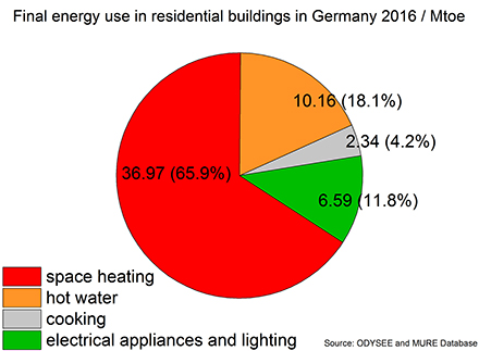
Figure 1. Final energy use in residential buildings in Germany 2016 in Mtoe and (percentage share). Graph based on data from the ODYSEE MURE Database (2015).
A detailed analysis on the performance of European buildings also comes to the result that in northern European nations around 80% final energy demand is required for space heating and domestic hot water (Economidou et al., 2011). And not only that the heat demand of buildings represents the largest share it is also (in general) mainly supplied by the combustion of fossil fuels. In the EU 50% of the heating energy in buildings comes from gas and another 25% from oil and coal (ODYSSEE-MURE, n.d.; Energy efficiency trends and policies in the household and tertiary sectors energy efficiency trends and policies in the household and tertiary sectors an analysis based on the, n.d.; ODYSEE MURE Database, 2015). The figures from 2016 for Germany are similar, showing over 80% share of fossils fuels (Lopez et al., 2018) and a very low renewable heat supply of 13.5%, which can mainly be dedicated to the combustion of biomass including wood pellets (Bundesumweltamt, 2019).
On the other hand the electricity production from renewable sources in particular photovoltaic (PV) systems and wind farms increased considerably over the last years, resulting in a share of 37.8% (Bundesumweltamt, 2019) in the electricity sector. Accordingly the total installed PV capacity in Germany accounts for 46 GWPeak at the end of 2018. The global trend is similar where a huge increase in the installed capacity in particular of solar PV systems was reported (REN 21, 2019).
From the discussed numbers it becomes clear that the integration of renewable heating systems has been neglected in the past decades while the installation of PV systems was supported by a significant cost decrease and additional policy incentives in various countries. Nevertheless, this leads to the current situation, that the major end energy demand of buildings still require mainly fossil fuels and the renewable electricity production exceeds the electricity demand of the building by far. This discrepancy on the supply and demand side is even reinforced due to the very large seasonal difference between them. While PV systems prevalently produce at daytime during the summer month, the largest heat demand occurs during the winter months. Thus, a simple power to heat concept, without a suitable seasonal storage solution, is not sufficient to increase the use of PV power for the heating system. Therefore, also typically only 30% of the produced electricity from roof top PV-systems is consumed in the building itself. For the overproduction, most of the PV installations are connected to the grid (IEA, 2013).
As a consequence large power flows between the households and the grid occur, which creates problems to the grid management and causes economic losses for the end user (Vieira et al., 2017). Since the cost of self-produced electricity is nowadays lower than the retail price of electricity in some countries (IEA, 2013), self-consumption turns out to be the most profitable option for the system owner. Taking both aspects together the system owners want to increase their self-consumption of the PV power while the purchase of fossil fuels to satisfy the heat demand, should be reduced. A solution to this would be a long term storage technology capable to achieve a seasonal shift of surplus electricity production and the heat demand of the building. However, none of the existing seasonal storage technologies addresses this mismatch between supply and demand sufficiently.
The reasons why there is no satisfactorily seasonal energy storage system available yet, lie in the generally very high technological and economical requirements for such a system. The required storage capacity for space heating is very large. Depending on the climate zone and the size and insulation of the building, between 1,500 and 10,000 kWhthermal energy per year are required (ODYSEE MURE Database, 2015). Concurrently, the storage system undergoes only one cycle per year, thus a total number of 20 cycles over the assumed lifetime. Taking into account that the investment in a storage system generally amortizes by the value of the energy supplied in every discharge cycle, it becomes clear that a seasonal storage system only allows for very low cost per stored kWh of thermal energy. This is also the reason why electrical energy storages, even if the currently prospected future cost reductions to 175 US$/kWh (Schmidt O. et al., 2017) are reached, will not be economically applicable for seasonal storage. Besides these already challenging economic constrains, an additional technological challenge arises since the energy must be preserved for a period from 2 to 6 month. Under these circumstances the storage systems energy losses over time clearly need to be minimal. Struggling with these challenging boundary conditions, only a few technologies or concepts exist for seasonal heat storage, which are in different states of development. These are mainly solar thermal collectors in combination with different conventional thermal storage systems, power to gas, and heat pumps.
Decentralized solar thermal collectors systems, including a hot water storage system, are readily available on the market and they have a higher solar to low temperature heat efficiency than electricity based heating systems. However, in cold countries the systems generally cover only up to 35% of the total heat demand of the building. Due to heat losses, long term storage with hot water is generally not feasible for small scale systems (e.g., single family building). Centralized large scale seasonal water storage systems are possible due to the better ratio of volume to surface area. Generally they cover up to 50% of the heat demand (Bauer et al., 2010), with higher solar shares possible. Several projects with different types of large scale seasonal storages are currently in operation or under construction and well-summarized in a review article of Xu et al. (2014). While the technology is promising under some circumstances, for example the development of new residential districts, it is also obvious that it is hardly applicable for retrofitting of existing buildings in densely populated districts.
The use of renewable power to produce synthetic fuels, or gases (e.g., hydrogen) is one promising option regarding long term storage of energy (Gerbert et al., 2018). The produced gas can be stored easily decentralized in small pressure tanks, centralized in already existing gas caverns or even the gas grid. Additionally the storage of energy rich gases is in principal free of losses, thus infinitely long term storage periods, with the release of energy at the time of demand are possible. For the building application the synthetic produced gas would just replace the fossil fuel in the conventional boiler system. Even though the approach sounds promising because a lot of the already existing infrastructure could be used further, the current drawbacks of the power to gas technology are rather low efficiencies over the whole process chain combined with the requirement of capital intensive apparatuses. Consequently, this technological pathway is currently assumed to be the most costly way to avoid CO2 emission by the replacement of fossil fuels in the heating sector (Gerbert et al., 2018).
Heat pump systems are available on the market and capable to couple the electricity with the heating sector. While such a system helps to increase the self-consumption of the PV production there is still a large mismatch between the electricity supply and the heat demand. Clearly during the winter time when the largest heat load occurs only very little electricity is available from the PV system. Even in combination with hot water storages, the total self-consumption is only extended to 40% of the produced electricity while 60% is still given to the grid (Williams et al., 2012). Current investigated combinations of thermal storages and heat pumps therefore do not achieve the desired seasonal shift sufficiently. The same drawback applies for other power to heat concepts, where simply electric energy is converted into thermal energy and stored in sensible or latent storage tanks. A seasonal shift can only be realized in centralized large scale storage tanks, but heat losses impede decentralized seasonal storage.
Thermochemical storage systems are generally promising for seasonal storage applications. The two distinct attributions of high energy densities and the loss free storage principle predestine these materials for long term storage tasks. Therefore, this topic is widely researched, but the technology level of the systems is still low. Thermochemical storages can be distinguished according to the mechanism of the storage principle, which is either a chemical reaction or a sorption process. In particular the sorption materials, but also some chemical reactions of salt hydrates, have been investigated for the application in seasonal storage systems. Scapino et al. recently summarized the different materials as well as their state of technology in a review article (Scapino et al., 2017a). In a cost analysis from the same group they concluded that major drawbacks of the systems are, besides technological challenges in the reactor development, the storage material costs. Prices per kWh of stored thermal energy are still too high to allow an economic operation of a seasonal storage system (Scapino et al., 2017b).
To overcome the presented drawbacks of the discussed technologies for long term storage in buildings, this paper presents a novel technological concept for a decentralized long term storage system. The concept is based on a thermochemical reaction which is charged with electrical energy and delivers thermal energy during the discharge phase. Thus, the system addresses the actual required shift from surplus electricity in the summer to the heat demand in the winter. The reaction material has two major advantages compared to so far analyzed thermochemical storage materials for seasonal storage. First the reaction material cost is 7–8 times lower and second, the discharge reaction can be performed with liquid water instead of water vapor which enhances the discharging procedure technically and energetically. This paper outlines for the first time a conceptual process design of this novel storage technology, including a detailed proposal for the thermochemical reactor. Based on the energy flows and the general demand situation of the building theoretical reachable efficiencies, storage densities, as well as required storage sizes for the systems are derived.
Novel Concept for Seasonal Storage in Buildings
Thermochemical Storage Material
As discussed in the introduction several thermochemical materials, mostly salt hydrates and zeolites, are under investigation for seasonal storage purposes. For almost all systems currently the material costs are still one major drawback on the way to market entrance. In contrast metal hydroxides have barely been considered for the application in buildings. One reason for this might be that generally higher reaction temperatures of more than 200°C are required, which impedes a charging of these systems by non-concentrating solar thermal collectors. Nevertheless, some metal hydroxides have promising characteristics for seasonal storage and, in our novel concept; the charging procedure is powered by electricity, which easily enables higher charging temperatures. The seasonal storage concept presented in this work is therefore based on the thermochemical reaction of calcium hydroxide (Ca(OH)2). Ca(OH)2 decomposes under the supply of energy at temperatures above 450°C to calcium oxide (CaO) and water vapor according to the following reaction equation:
The idea of storing energy with the reaction system has been proposed already decades ago (Ervin, 1977). If surplus energy (e.g., from renewable sources) is available, the dehydration of the hydroxide to the oxide is carried out (charging phase). The freed water vapor can easily be separated from the solid by condensation. The energy is preserved, for an infinite amount of time, in the form of the chemical potential of the calcium oxide. Once energy is required water vapor or liquid water is brought in contact with the calcium oxide again and the exothermal back reaction starts, releasing the energy (discharging phase).
The reaction system is of particular interest for energy storage purposes since it offers several advantages. Firstly the material is available in abundance all over the world and the lime production is among the biggest chemical industries in the world. In the year 2011 330 million tons of lime were produced worldwide (USGS, 2011). Therefore, the raw material is generally available at low cost, currently at around 100 EUR/t. Together with the theoretical energy density of the material of ~370 kWh/t (Afflerbach et al., 2017) the systems offers a very cheap energy storage capacity of 0.27 EUR/kWh. Further advantageous is the reversibility of the reaction which was experimentally demonstrated up to more than 1,000 cycles (Rosemary et al., 1979) and a fast reaction kinetic (Schaube et al., 2012). Taking these aspects together and adding, that the thermochemical storage principal itself is generally free of losses, the material perfectly fulfills all required criteria's for a cost effective seasonal storage system. However, the application of the material for seasonal storage in buildings has not been considered yet. Therefore, we developed a technological concept for decentralized long term energy storage in buildings that connects the locally available electricity production from the local thermal energy demand based on the abundant reactants CaO and water.
Conceptual Process Design for Seasonal Storage System
Figure 2 shows the conceptual process design of the storage system. The system consists of one container for the storage material, a material transport system, the thermochemical reactor and a hot water storage tank. The underlying operation strategy for charging is: if electricity supply from renewables (e.g., roof top PV or even from the grid at low cost) exceeds the electricity demand of the house the storage charging operation starts. Calcium hydroxide is transferred from the storage container to the reactor unit. The reactor is heated up electrically to temperatures above 450°C in order to perform the dehydration of the calcium hydroxide. During the dehydration water vapor is freed from the solid material. From our own experience with lab scale reactors we can state that a fine filter mesh of 5 μm pore size sufficiently separates storage material particles from the reaction gas (Cosquillo Mejía et al., 2020). Thus, the released vapor is pure uncontaminated water. The vapor, cools down first in the preheater to 100°C and then condenses in a heat exchanger (HEX1, Figure 2) to 40–60°C. The condensation temperature determines the water vapor pressure in the reactor and thus the reaction temperature. Even at condensation at 60°C the corresponding vapor pressure is 200 mbar and the corresponding equilibrium temperature of the reaction is 430°C. By this means a charging temperature of 450°C in the reactor can be controlled. 20 Kelvin distance to the equilibrium temperature is reasonable to achieve sufficiently fast reaction kinetics. Moreover, the operation principle allows the useful integration of the thermal energy, mainly the heat of condensation of the vapor, which necessarily occurs during the charging process to charge the hot water tank of the building. After the energy content of the water has been extracted, the cooled down water can easily be disposed to the sink.
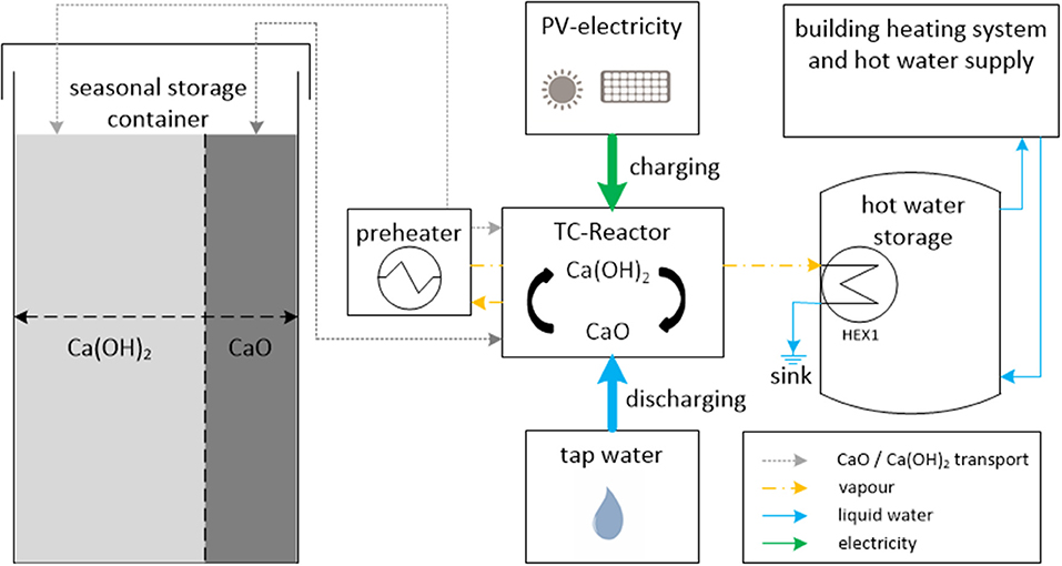
Figure 2. Conceptual process design for a decentralized, seasonal thermochemical storage system based on the reaction material Calcium Hydroxide.
The sensible energy of the vapor and the hot storage material is exchanged in the preheater to heat up Ca(OH)2 before it enters the reactor. Please note that we propose a semi continuous batch process, thus sensible heat of the material is exchanged when material batches are exchanged after the reaction was completed. The preheater can be executed as a gas solid heat exchanger. During the reaction the sensible heat of the vapor will be transferred to the next batch of cold storage material in the preheater. After the reaction is finished a nitrogen flow is applied for a short time transferring the sensible heat of the material in the reactor to the fresh Ca(OH)2 batch in the preheater.
The storage phase starts with the transport of the CaO. In the container the CaO can be stored at room temperature, for an infinite amount of time, without losing the energy content of its chemical potential. To minimize the required volume and investment cost for the long term storage container we propose to use only one container for both material states of CaO and Ca(OH)2. In a technical realization, the volume available for each material can be adjusted by a movable wall or flexible foil inside the container.
The idea is further, that the charging procedure is carried out every time when there is surplus electricity available. For instance, during the summer, every day CaO is produced and thus the energy content charged into the long term storage continuously increases over the period. This operation principle allows that the reactor only requires a small power for charging of around 5–10 kW but at the end of the charging period a large amount of thermal energy is stored and available for heating purposes.
The strategy for discharging in winter is comparable to the charging: only as soon as the heat demand of the building cannot be satisfied by available renewable energy sources, the long term storage system goes into discharge operation. For the discharging procedure, CaO is now transported from the container to the reactor. In the reactor liquid water, which can be taken from the tap is added to the calcium oxide powder. The exothermal back reaction immediately starts, releasing heat at ~100°C. Via a second water circuit the released heat of the exothermal reaction is transferred to the hot water storage tank which in turn supplies the thermal energy to the building. Ca(OH)2 is transported back to the container and remains there until excess renewable electricity is available to start over the charging of the material.
Reactor Development
As already mentioned a seasonal storage system must be extremely cheap in order to amortize over the total low cycle numbers. For the presented concept, the cost of the storage material even for large capacities is almost neglectable. The reactor thus causes the main investment cost. We therefore aimed to develop a compact reactor design with a high power density. In order to achieve these goals, assumptions based on the definition of the thermal power of the reactor by the equation have been made. The required heat exchange surface (A), has generally the greatest influence on the reactor cost, thus it should be minimized. From that perspective, increasing either the heat transfer coefficient (k), or the temperature difference (ΔT) or both, would lead to a smaller required heat exchange surface. Increasing the temperature difference seems the easiest way, but for chemical reactions the required reaction temperature limits this measure. For example, the dehydration of Ca(OH)2 requires a minimal temperature of 450°C (Schmidt M. et al., 2017), under atmosphere pressure, to ensure a sufficiently fast reaction. This means that if the maximum temperature of the heat source is 600°C, the temperature difference accounts 150 K. A further increase of the heat source temperature would lead to higher requirements for the reactor steal alloys, which in turn increases costs significantly. As a consequence, the power density can only be further increased through an enhanced heat transfer coefficient k.
It is well-known that in indirectly heated fixed beds the heat transfer coefficient is generally dominated by the low thermal conductivity of the reaction material of 0.1 W/mK. Fluidized bed reactors promise much larger heat transfer coefficients. However, the fluidization of the material also requires large gas volume flows, which reduces the energy efficiency of the storage process. Furthermore, additional devices are required to separate the fluidizing gas from the particles making this concept rather feasible for industrial applications than small scale decentralized systems in buildings. One concluding design criteria was that the system should be operated with basic industrial grade Ca(OH)2. Industrial grade material is generally a very fine powder with a mean particle diameter of 5 μm. A reactor which can be operated with the Ca(OH)2/CaO powder has the advantage that no material modifications, like pelletizing or addition of flow improving additives is required. The material hence remains in it's natural form and by this approach the intrinsic advantage of availability in large scale at low cost is preserved.
Based on these considerations we developed a new reactor concept with the aim of reaching a very high heat transfer coefficient but with only minimal increase of the reactor complexity. The main approach was to mechanically mix the powder material in the reactor. This should change the dominating heat transfer mechanism from thermal conduction through a fixed particle bed to heat transfer which is dominated by contact between the single particles and the heat exchange surface. An additional constraint of our system is that the same heat exchange surface should be used for the electrical charging procedure as well as the thermal discharge procedure, again in order to minimize complexity and required surfaces for heat exchange.
Figure 3 shows the final design of the developed reactor. The general idea was to adapt the plow share mixer concept, known from mixing processes in the chemical industry, to build a compact thermochemical energy storage reactor. Through the inlet flange the storage material falls freely into the reaction chamber. There the plow shares rotate at adjustable rotation speeds creating a so called mechanically assisted fluidized bed. By this means, the particles are intensively mixed and every particle comes immediately in direct contact with the heat exchange surface (the surrounding casing). The casing pipe is basically a double walled tube heat exchanger (compare Figure 3), because it serves for two different functions. For the charging process the outer shell is heated up to 600°C with electrical heating wires delivering the required energy for the dehydration reaction.
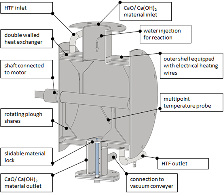
Figure 3. Thermochemical storage reactor for electrical charging and thermal discharge with liquid water.
For the discharging process liquid water is injected through a spray nozzle situated in the material inlet flange. The fine spray of water together with the rotating plow shares helps to equally distribute the water in the reaction chamber Please note, that the discharging process with liquid water is different to the well-published investigations on the reaction with a certain vapor partial pressure. CaO also reacts with water in liquid state and vapor is not necessarily required. Still it might be the case that due to the heat release some water drops evaporate creating a fog like atmosphere in the reactor. Maximum the amount of water which can be uptaken by the CaO is added thus after the completed reaction only fine powder of Ca(OH)2 is again present in the reactor. The heat released by the exothermal reaction is taken up, by a heat transfer fluid flow, which can be adjusted inside the shell of the reactor. By adjusting the water injection for the reaction, and the volume flow of the heat transfer fluid, the temperature in the reactor can be controlled. This new discharge operation principle will experimentally be analyzed, regarding the controllability of the process temperature, in upcoming works with this reactor.
The material outlet is located at the bottom of the reactor and equipped with a slidable lock. The lock slides down once the material has completely reacted and a vacuum conveying system removes the material out of the reaction chamber. Vacuum conveyers can easily handle the small powder particles and have a low energetic expense. The required auxiliary energy for the conveyer depends on the transport length and will typically be in the range of 1–3% from the energy content of the transported material.
The reactor has an outer diameter of 0.35 m and a length of 0.3 m. The heat exchange surface of the inner shell accounts 0.26 m2, and the volume ~20 l. According to literature in mechanically fluidized beds heat transfer coefficients of 300 W/m2K can be reached. Taken together with the temperature difference of 150 K a heat exchange surface of 0.22 m2 would be required for a thermal power of 10 kW, which is the target power required for a single family building. From this dimensions it becomes clear that the reactor is compact and volume wise would easily fit into existing technical rooms in the building. However, if the theoretically power density will be reached still needs to be proven experimentally, which is currently in preparation.
Energy Balance and Theoretical Efficiency
In order to assess the possible efficiency of the system it is essential to have a closer look on the mass and energy flows during the process. Figure 4 shows the energy flows during the charging procedure. The arrows on the left side represent the specific amount of energy required to heat up the Ca(OH)2 from 20 to 500°C (47.3 kJ/molCa(OH)2) and to the enthalpy of reaction [104.4 kJ/molCa(OH)2]. On the right side the energy flows out of the reactor are presented. The blue arrow symbolizes the water vapor which leaves the reactor. The vapor contains sensible heat (18.1 kJ/molH2O) for cooling down from 500 to 100°C. The larger part, 40.6 kJ/molH2O is the enthalpy of condensation which is released during condensation at a constant temperature. The hot CaO coming out of the reactor contains 87 kJ/molCaO of which 22 kJ/molCaO is sensible heat of the cooling from 500 to 20°C and 65 kJ/molCaO are preserved as the chemical potential of the calcium oxide.
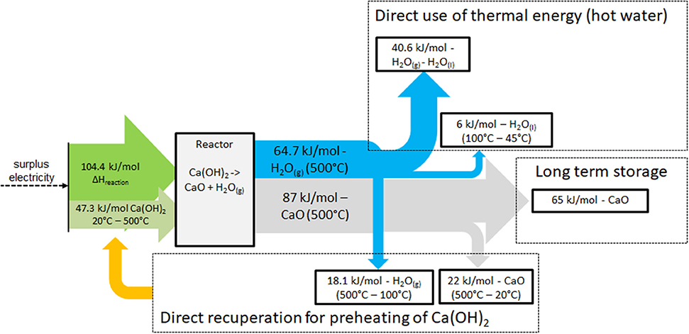
Figure 4. Energy flows during the dehydration of Ca(OH)2 to CaO and water vapor.
The presented energy balance reveals that during the charging procedure energy flows of three different natures occur: the sensible heat of the mass flows, the heat of condensation of the vapor and the chemical potential of the CaO. Only the chemical potential can be stored seasonally and the sensible and latent thermal energy must be directly integrated in order to reach a reasonable storage efficiency.
To meet this requirement, as pointed out in Figure 4, part of the sensible heat of the water vapor and the CaO (together 40.1 kJ/mol) is directly recuperated for the preheating of the hydroxide. Heating up the hydroxide from 20 to 500°C demands 47.3 kJ/molCa(OH)2. The recuperation thus reduces the required energy for heating up the hydroxide to 7.2 kJ/molCa(OH)2 (compare Figure 4). Adding the reaction enthalpy of 104.4 kJ/mol Ca(OH)2 the total energy, supplied electrically, accounts 111.6 kJ/molCa(OH)2. The remaining 46.6 kJ/molH2O sensible and latent heat of the water vapor could be used for the domestic hot water production (compare Figure 2), which is also required during the summer time. And finally 65 kJ/molCaO are charged into the long term storage. If we relate now the output energy flows to the energy input of 111.6 kJ/molCa(OH)2, presuming ideal recuperation, the numbers reveal that ~42% of the electrical energy is converted into thermal energy (sensible and latent) and ~58% into chemical potential. Or expressed in energy quantities, the system converts 1 kWh of available electric energy in 0.42 kWh directly usable thermal energy and 0.58 kWh seasonally stored energy. So far this is an ideal consideration neglecting conversion and heat exchange losses. Nevertheless, the ratio defines a crucial characteristic of the storage system because the values are fixed and determined by the properties of the involved reactants. The values describe the intrinsic maximum which can be reached with the reaction system and the two energy flows obtained during the charging process can be described by the following equations:
Overall Storage Efficiency Including Heat Exchanger Losses
For this first potential analysis it is reasonable to neglect the conversion efficiency from the electrical input to thermal energy because the conversion efficiency of electrical heaters is potentially close to 100%. The chemical stored energy in the CaO (qlong term storage) at ambient temperature is also free of losses over time. Preliminary studies with the reaction showed that the reaction kinetics at a temperature above 450°C is fast and will not limit the charging process.
Energy losses which will play a considerable role in the real system are losses due to the heat exchange and integration of the sensible and latent heat flows during the charging process. One heat exchanger (HEX1, Figure 2) is required for the direct integration of the heat of condensation for the hot water production. To account for these losses Equation 1 needs to be multiplied with an efficiency factor for the heat exchange (ηHEX1). The useful thermal energy of the storage system is the sum of the energy preserved in the long term storage plus the energy directly used for the domestic hot water production during charging operation. Including the heat exchanger efficiency it can be ascribed as:
Heat exchange is also required for the recuperation of the sensible heat of the reactants (qrecuperation = 40.1 kJ/mol, outlet of reactor) for the preheating of the Ca(OH)2 (qpreheating = 47.7 kJ/molCa(OH)2, inlet of reactor). The amount of energy recuperated will be lowered due the efficiency of the heat exchanger for recuperation (ηrecuperator). The difference of the energy recuperated to the energy required for the preheating as well as the enthalpy of the reaction is supplied by the electrical heaters. The input of electrical energy in the system is therefore ascribed as:
For the heat exchangers an efficiency of 95% (ηrecuperation = ηHEX1 = 0.95) is assumed. The theoretical overall efficiency of the storage system can now be calculated by relating the useful thermal energy output to the required input of electrical energy, thus the quotient of Equations 3 and 4:
An overall efficiency of the storage system of 96% could be reached. It is clear that this is rather an idealized maximal value, the real efficiencies need to be validated experimentally and are presumably lower. In particular a heat exchanger efficiency of 95% is rather top end, but a recent study showed that if the heat exchanger is particularly designed for the application 95% regeneration efficiency can be reached (Kostukov et al., 2019). Moreover, the real efficiency of the heat exchangers and the reactor are not known yet and the purpose of this first theoretical analysis is to determine the theoretical potential of the system. Also it revealed the fundamental operation principle which should be applied in models for more detailed systems simulation studies. The efficiency value serves as a baseline to evaluate the quality of a laboratory system, which we are currently bringing in operation.
Beyond that, the analysis reveals an effect that has a severe influence on the efficiency of the storage system in the real application: The question how much of the thermal energy occurring during the charging phase can really directly be used in the building. The effect on the efficiency is analyzed more detailed by a case study in chapter 2.4, taking basic assumptions of the heat demand of the building into account.
Storage Density
From the energy balance performed in performed in the previous section it was calculated that the 65 kJ/mol are preserved in the long term storage. For this part of the energy it can be assumed that it can completely be used for space heating during the winter time. This is because it is stored free of thermal losses and it will only be released when there is a heat demand in the building. Additionally since the reaction is triggered by liquid water from the tap no additional thermal energy is required during the discharge operation. The value from the energy balance can be confirmed by calculating the theoretical enthalpy of the back reaction by the standard enthalpies of formation from the involved reactants (enthalpies of formation and references given in Table 1):
This value thus is also fixed by the involved reactants and defines the storage density of the long term storage part which can also be related to the mass of the CaO by:
The gravimetric energy density is related to CaO and the exothermal reaction with liquid water. By this value the mass required for a certain amount of thermal energy in the long term storage can be determined. However, to determine the required volume of the storage system, the volumetric energy density is the determining factor. The volumetric energy density needs to be related to Ca(OH)2 because the hydroxide material has the lower density. And it is clear that after the winter discharge phase, all oxide is converted into hydroxide, which needs to fit into the storage container. Furthermore, for the determination of the volumetric energy density it is important to take the bulk density of the hydroxide into account. The bulk of the non-compressed powder material has very a high porosity of 0.75 leading to a bulk density of ~540 kg/m3. Slight compressing of the powder material before storage could decrease the porosity to 0.6 which would result in a higher bulk density of 880 kg/m3. The volumetric energy density can thus be calculated to a possible range according to the achievable bulk density during the storage phase:
With the calculated energy density the required storage container volume can be estimated related to the (winter periods) heat demand of the building.
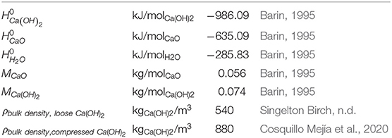
Table 1. Characteristic values of the reaction system.
Estimated System Design for Application in Single Family Buildings
Operation Modes
As already discussed the integration of the thermal energy released during the charging process has a severe impact on the efficiency of the storage system. Therefore, we will discuss now different operation strategies of the system taking some basic boundary conditions for the domestic hot water and space heat demand of the building into account.
A first operation strategy is that the storage system is only charged as long as the thermal energy released during the charging process is required for the daily domestic hot water production. The hot water demand (Qhot water, daily) is constant every day of the year, and mainly depends on the number of occupants in the building. Based on this assumption, the directly used thermal energy per day (kWh) can be set equal with the daily hot water demand:
Implementing Equation 6 and Equation 2 in Equation 5 the efficiency can be ascribed as:
If the system should be operated at the maximum possible efficiency of 96% (called now nominal operation mode with εnominal = 0.96), the maximum amount of electrical energy which can be incorporated into the storage system every day can be calculated by transposing Equation 7 to:
The calculation reveals, that for the nominal operation mode the daily maximum amount of electrical energy is limited to 2.63 times the daily hot water demand of the building. Please note, that losses due to the heat exchangers (ηHEX1 and ηrecuperation), as described in section Thermochemical Storage Material, are considered in this equation, by setting εnominal = 0.96.
Based on the limit of the daily electrical energy input, also the maximum energy storage capacity which is charged into the long term storage per day (Clong term charged, daily) is limited and can be calculated by applying Equation 2:
A second operation strategy is, that the storage charging continues as long as excess electricity is available, even if the domestic hot water demand is already satisfied. This means that excess thermal energy during the charging process needs to be rejected to the ambient. Consequently part of the energy is lost and the overall storage efficiency decreases. The coherence can be seen in Equation 8. When the daily hot water demand is constant but the electrical energy increases to more than the nominal amount of electrical energy (or in other words more than 2.63 times the daily hot water demand), the overall storage efficiency decreases. However, even though the overall efficiency decreases, the operation mode allows the integration of more electrical energy and thus also enables the charging of larger capacity of thermal energy into the long term storage. In order to better understand the impact of these operation modes we present now concrete numbers for different energy demand scenarios of the building.
System Design Related to the Buildings Energy Demand—Case Study
The case study is based on simplified assumptions for the buildings demand. However, the numbers provide a first idea of the capabilities of the system. According to a study from Fuentes et al. the daily domestic hot water demand for a household with 3 persons can be estimated with ~10 kWh/day (Fuentes et al., 2018). Applying this value in Equation 8 and Equation 9 the maximum daily electrical charging energy as well as the maximum thermal energy charged into the long term storage can be calculated.
Figure 5 shows the amounts of energy for the different operation modes. For the nominal operation mode the electrical energy which can be charged into the storage system must be limited to 26.3 kWh's in order to maintain the highest possible efficiency of 96%. The energy amount corresponds to 2.6 full load hours of a 10 kWpeak PV Installation. A 10 kWpeak systems demands ~80 m2 rooftop surface, and represent a reasonable size for installations in Germany. The amount of thermal energy charged into the long term storage is limited to 15.25 kWh's per day. Simultaneously 10 kWh's of thermal energy, which occurs during the charging process, are used for the hot water production. Another 1.05 kWh's represent thermal losses due to heat exchange.
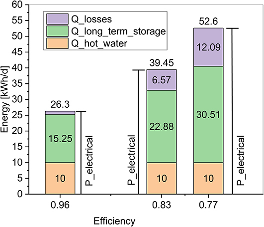
Figure 5. Daily energy amounts for losses, hot water production, and long term storage charging for different amounts of total used electrical charging energy.
For the second operation mode it is assumed that 1.5 and 2 times more electrical energy than in the nominal operation mode is used to charge the storage system. Thus, in total 39.45 and 52.6 kWh's electrical energy, corresponding to 4 and 5.3 full load hours of the PV system, are used for storage charging (compare Figure 5). As mentioned, this means that the charging continues even though the hot water demand of the building is already satisfied and excess thermal energy needs to be rejected to the ambient. The effect of this operation mode can be seen by comparing the different shares of energy in Figure 5. While the hot water demand remains constant at 10 kWh's per day for every case, the total amount of energy charged in the long term storage increases with increased electrical input, but it's share remains at 58%. As previously mentioned this is an intrinsic value due to the nature of the reactants. The remaining difference between the energy in the long term storage and the amount for hot water production are energy losses. The losses in the figure represent the sum of heat exchanger losses and excess thermal energy which needs to be rejected to the ambient. It can be seen that with increasing operation hours, the share of these losses increases and hence the efficiency of the storage system drops to 0.83 and 0.77 for the representative operation examples.
To calculate the total energy capacity charged into the long term storage over the whole summer period, the values for the daily energy charged into the long term storage, given in Figure 5, can be multiplied with the amount of charging days. For the nominal operation mode the total charged storage capacity would account 1,525 to 2,745 kWh's, assuming that the required renewable electricity is available at 100 to 180 days during the summer. For the second operation mode the daily energy amount in the long term storage increases to 22.88 or 30.51 kWh's, at an efficiency of 83 or 77%. Accordingly the total charged thermal energy will be 4,118–5,491 kWh's after 180 charging days. From the values, the general characteristic of the storage system becomes evident. If a high storage efficiency should be maintained the charged capacity in the long term storage is limited, and depends on the energy demand for hot water. Larger amounts of energy can be charged into the storage, but only with the price of lower storage efficiency.
Implications for the Capability of the Storage System
According to energy regulations for new buildings in Germany, the space heat demand for buildings constructed after 2009 is supposed to lie in the range of 15 kWh/m2a (passive house standard) and 90 kWh/m2a. While the average space heat demand for newly build houses in 2015 accounted 44 kWh/m2a (ODYSEE MURE Database, 2015). Assuming a 100 m2 living space, the annual space heat demand thus would account 1,500 kWh's for the passive standard house to 4,400 kWh's for an average modern building. Relating the space heat demand to our calculated stored thermal energy for the different scenarios we can see a generally good coherence. While the system operated at the highest efficiency of 96% and only 100 available charging days, the stored capacity would be sufficient to cover the whole space heat demand of the most energy efficient building. Operating the system at a lower efficiency of 77% and assuming 180 charging days, the stored energy capacity would approximately be sufficient to cover the heat demand of an average modern building. Taking the energy density for compressed powder, calculated in 2.3 into account, the required storage volumes vary between ‘7 and 25.5 m3 for the analyzed cases.
In addition to the storage material also water to perform the exothermal back reaction is required. Based on the molar masses given in Table 1, the amount of water required per kWh thermal energy can be calculated to ~1 kgwater/kWh Hence for the calculated energy storage capacity, the required amount of water for the whole heating period corresponds to 1,525–5,491 kgwater or ~1.5–5.5 m3. For comparison, the annual water consumption of one person accounts 46.3 m3 in average. The numbers show that the amount of water required for the reaction can be taken from the tap, since it would increase the overall water consumption of a four person household by only 3%. Taking water from the tap also has the advantage that the water which is freed during the charging procedure must not be stored and can be disposed to the households sink.
One important point which has been neglected in this first estimation is the impact of intermittency of the available renewable power on the systems efficiency. In general the system will be able to react quickly on fluctuating power by adjusting the mass flow (input) of the reactants in the designed power range of the reactor (e.g., 1–10 kW). It is only important, that during the charging time no longer periods of really zero electrical power occur, since this would cause a complete cool down of the whole system. The more often the reactor has to be heated up in relation to the operating hours the more the losses due to the heat up phase (of the reactor steel mass) could impact the overall efficiency. A detailed system simulation analysis e.g., with an hourly (or even higher) resolution, taking available weather data into account is therefore required to evaluate this impact. Additionally it is currently under investigation how model predictive control algorithms based on the weather forecast will help planning the operation of the reactor on the next day and thus minimize these losses.
Summarizing the estimations it becomes clear, that the efficiency as well as the required storage size cannot be stated in general. A detailed yearly simulation taking the buildings heat demand and the availability of renewable electricity in an hourly resolution into account is required. Simulations of this kind are currently ongoing and will allow more robust predictions on the storage system design. It is also clear that ideally the storage system, as well as the PV installation should be sized in dependence of each other applying an economic optimization. However, the presented considerations show that the system is capable to achieve the conversion and seasonal storage of renewable electricity to heat with potentially high storage efficiencies and at acceptable storage sizes.
In order to verify the elaborated promising theoretical performance of the storage system experimentally and to demonstrate the technological feasibility of the concept, a fully functional pilot plant has been developed and is currently brought into operation at our institute.
Conclusions
This paper presents the development of a novel concept which couples the power and heat sector by a cost and energy efficient long term storage system. The concept is based on the thermochemical reaction of calcium hydroxide to calcium oxide and water vapor, which yet has never been considered as seasonal storage for buildings. In contrast to previously presented seasonal storage concepts not solar thermal energy but renewable electricity is used to charge the storage system. Even though solar thermal collectors have a higher solar to low temperature thermal energy efficiency than heating systems based on solar electricity, the approach has promising advantages. The electricity based principal in general allows higher reaction temperatures and thus higher energy densities of the reactive materials. Moreover, in our concept the discharge reaction can be performed with liquid water which directly supersedes the preparation of water vapor, for the discharging reaction during the winter time—an intrinsic energy loss, for all of previously reported seasonal thermochemical storage systems. Last mentioned also different sources of renewables, for example overproduction periods of wind farms, could be balanced with the storage system, supplying much needed grid stabilization.
A generic energy balance of the charging process revealed an important characteristic of the thermochemical storage system: At maximum 58% of the electrical energy input is converted into chemical potential and can be stored seasonally. The remaining 42% of the energy input is converted into sensible and latent thermal energy of the reactants and needs to be used directly during the charging period. The derived equations serve as the basis for more detailed yearly simulations of the operation of the storage system in buildings.
Taking the general characteristic of the storage concept into account two different generic operation principles have been identified and analyzed. In the first operation mode, the charging is only carried out, as long as the waste heat can be used to satisfy the hot water demand of the building. With this operation mode the storage system can be operated with the highest efficiency of ~96% but the energy capacity available in the storage after the charging period is limited. Nevertheless, the results, based on simplified assumptions of the buildings demand and supply characteristics, showed that potentially 1,525 kWh's thermal energy could be stored which would be sufficient to cover a large part of the space heat demand of an energy efficient modern single family buildings. The presented operation principle is generally novel, because the charging of the storage is adapted to the buildings heat demand during the summer time. While in contrast to that the so far discussed seasonal storage systems are always only charged with excess solar thermal energy once the heat demand of the building is already satisfied. The proposed principal has thus the advantage that all heat flows, during charging as well as discharging, are usefully integrated to supply the buildings energy demand. This is one reason, why for a seasonal storage system comparably very high thermal storage efficiency can be reached.
A second operation mode allows the continuation of the charging process as long as excess electricity is available even if excess thermal energy needs to be rejected to the ambient. This operation would enable to design the PV and the storage system in accordance that the stored thermal energy after the charging period is sufficient to cover the whole heat demand during the winter time. The system thus would be capable of achieving 100% autarkic coverage of the heat demand over the whole year, but supposable only with the price of a lower overall storage efficiency.
It can be summarized that the thermochemical reaction system of Ca(OH)2 is a suitable storage material for seasonal energy storage because it is very cheap, abundantly available, the chemical potential is stored free of losses and it offers a storage density of 132–215 kWh/m3. The results of this study show that the storage concept is capable to achieve the favorable seasonal shift from renewable electricity to heat demand in the winter which represents the actual supply and demand situation in the building. Moreover, the system could help to reduce stresses to the local electrical grids and increase the share of renewables in the heating sector, thus reducing CO2 emissions. Upcoming works will include the experimental validation of the storage system performance with a pilot plant which is currently in operation at our institute. Additionally more detailed simulation studies on the application of the storage system in residential buildings are required to confirm its potential for different use cases.
Data Availability Statement
The raw data supporting the conclusions of this article will be made available by the authors, without undue reservation, to any qualified researcher.
Author Contributions
MS: main development work and elaboration of the manuscript. ML: discussion partner on scientific content. All authors contributed to the article and approved the submitted version.
Conflict of Interest
The authors declare that the research was conducted in the absence of any commercial or financial relationships that could be construed as a potential conflict of interest.
References
Afflerbach, S., Kappes, M., Gipperich, A., Trettin, R., and Krumm, W. (2017). Semipermeable encapsulation of calcium hydroxide for thermochemical heat storage solutions. Solar Energy 148, 1–11. doi: 10.1016/j.solener.2017.03.074
Bauer, D., Marx, R., Nußbicker-Lux, J., Ochs, F., Heidemann, W., and Müller-Steinhagen, H. (2010). German central solar heating plants with seasonal heat storage. Solar Energy 84, 612–623. doi: 10.1016/j.solener.2009.05.013
Cosquillo Mejía, A., Afflerbach, S., Linder, M., and Schmidt, M. (2020). Experimental analysis of encapsulated CaO/Ca(OH)2 granules as thermochemical storage in a novel moving bed reactor. Appl. Therm. Eng 169:114961. doi: 10.1016/j.applthermaleng.2020.114961
Economidou, M., Atanasiu, B., Despret, C., Maio, J., Nolte, I., Rapf, O., et al. (2011). Europe's Buildings Under the Microscope. A Country-by-Country Review of the Energy Performance of Buildnings. BPIE.
Energy efficiency trends and policies in the household and tertiary sectors energy efficiency trends and policies in the household and tertiary sectors an analysis based on the ODYSSEE and MURE databases. ODYSEE-MURE Project (2015). Available online at: https://www.buildup.eu/en/practices/publications/energy-efficiency-trends-and-policies-household-and-tertiary-sectors
Ervin, G. (1977). Solar heat storage using chemical reactions. J. Solid State Chem. 22, 51–61. doi: 10.1016/0022-4596(77)90188-8
Fuentes, E., Arce, L., and Salom, J. (2018). A review of domestic hot water consumption profiles for application in systems and buildings energy performance analysis. Renew. Sustain. Energy Rev. 81, 1530–1547. doi: 10.1016/j.rser.2017.05.229
Gerbert, P., Herhold, P., Burchardt, J., Schönberger, S., Rechenmacher, F., Kirchner, A., et al. (2018). Klimapfade für Deutschland. BCG.
Kostukov, A. V., Kosach, L. A., and Gornovskii, A. S. (2019). “Microturbine with heat exchanger with regeneration ratio equal 95%,” in Proceedings of the 4th International Conference on Industrial Engineering (Cham: Springer), 2229–2235.
Krese, G., KoŽelj, R., Butala, V., and Stritih, U. (2018) Thermochemical seasonal solar energy storage for heating and cooling of buildings. Energy Build. 164, 239–53. doi: 10.1016/j.enbuild.2017.12.057
Lopez, E., Schlomann, B., Reuter, M., and Eichhammer, W. (2018). Energy Efficiency Trends and Policies in Germany – An Analysis Based on the ODYSSEE and MURE Databases. Fraunhofer Institute for Systems and Innovation Research ISI.
ODYSEE and MURE Database (2015). Available online at: https://odyssee.enerdata.net/database/ (accessed December 4, 2019).
Rosemary, J. K., Bauerle, G. L., and Springer, T. H. (1979). Solar energy storage using reversible hydration-dehydration of CaO-Ca(OH)2. J. Energy 3, 321–322.
Scapino, L., Zondag, H. A., Van Bael, J., Diriken, J., and Rindt, C. C. M. (2017a). Sorption heat storage for long-term low-temperature applications: a review on the advancements at material and prototype scale. Appl. Energy 190, 920–948. doi: 10.1016/j.apenergy.2016.12.148
Scapino, L., Zondag, H. A., Van Bael, J., Diriken, J., and Rindt, C. C. M. (2017b). Energy density and storage capacity cost comparison of conceptual solid and liquid sorption seasonal heat storage systems for low-temperature space heating. Renew. Sustain. Energy Rev. 76, 1314–1331. doi: 10.1016/j.rser.2017.03.101
Schaube, F., Koch, L., Wörner, A., and Müller-Steinhagen, H. (2012). A thermodynamic and kinetic study of the de- and rehydration of Ca(OH)2 at high H2O partial pressures for thermo-chemical heat storage. Thermochim. Acta 538, 9–20. doi: 10.1016/j.tca.2012.03.003
Schmidt, M., Gutierrez, A., and Linder, M. (2017). Thermochemical energy storage with CaO/Ca(OH)2–experimental investigation of the thermal capability at low vapor pressures in a lab scale reactor. Appl. Energy 188, 672–681. doi: 10.1016/j.apenergy.2016.11.023
Schmidt, O., Hawkes, A., Gambhir, A., and Staffell, I. (2017). The future cost of electrical energy storage based on experience rates. Nat. Energy 2:17110. doi: 10.1038/nenergy.2017.110
Singelton Birch (n.d.). SD30 Safety Data Sheet. Available online at: https://cms.esi.info/Media/documents/Singl_SD30data_ML.pdf (accessed June 25, 2020).
USGS (2011) LIME - USGS Minerals. Available online at: https://minerals.usgs.gov/minerals/pubs/commodity/lime/mcs-2012-lime.pdf (accessed January 12, 2017).
Vieira, F. M., Moura, P. S., and de Almeida, A. T. (2017). Energy storage system for self-consumption of photovoltaic energy in residential zero energy buildings. Renew. Energy 103, 308–320. doi: 10.1016/j.renene.2016.11.048
Williams, C. J. C., Binder, J. O., and Kelm, T. (2012). “Demand side management through heat pumps, thermal storage and battery storage to increase local self-consumption and grid compatibility of PV systems,” in IEEE PES Innovative Smart Grid Technologies Conference Europe (Berlin: IEEE), 1–6.
Keywords: thermochemical energy storage, calcium hydroxide/oxide, seasonal storage, power to heat, process design
Citation: Schmidt M and Linder M (2020) A Novel Thermochemical Long Term Storage Concept: Balance of Renewable Electricity and Heat Demand in Buildings. Front. Energy Res. 8:137. doi: 10.3389/fenrg.2020.00137
Received: 17 January 2020; Accepted: 04 June 2020;
Published: 17 July 2020.
Edited by:
Yulong Ding, University of Birmingham, United KingdomReviewed by:
Thomas Alan Adams, McMaster University, CanadaTingxian Li, Shanghai Jiao Tong University, China
Adriano Sciacovelli, University of Birmingham, United Kingdom
Seon Tae Kim, Tokyo Institute of Technology, Japan
Copyright © 2020 Schmidt and Linder. This is an open-access article distributed under the terms of the Creative Commons Attribution License (CC BY). The use, distribution or reproduction in other forums is permitted, provided the original author(s) and the copyright owner(s) are credited and that the original publication in this journal is cited, in accordance with accepted academic practice. No use, distribution or reproduction is permitted which does not comply with these terms.
*Correspondence: Matthias Schmidt, bWF0dGhpYXMuc2NobWlkdEBkbHIuZGU=