 Boqi Xie
 Dongbo Zhao
 Tianqi Hong
- 1School of Electrical and Computer Engineering, Georgia Institute of Technology, Atlanta, GA, United States
- 2Argonne National Laboratory, Energy Systems Division, Lemont, IL, United States
Increasing distributed energy resources, especially the renewable energy resources (RESs) are being installed across power systems these years. These RESs, including solar photovoltaic, wind turbines, etc., provide opportunities for operators to improve power quality, enhance power system resilience, and help meet green energy goals. However, RESs also bring challenges to the operators. As the operating conditions of RESs vary drastically, power systems may experience larger dynamics compared with the traditional power systems with limited RESs. Such dynamics may impose some impacts on devices in power systems. Transformer, as one of the critical and expensive components in power systems, is in need to be protected and monitored constantly. With this said, monitoring and protection of transformers are significant and critical in power system industry as well as in academic research. This paper presents a comprehensive review of the existing transformer monitoring and protection methods. The paper first introduces monitoring and protection approaches for the legacy low frequency transformers, as those transformers are still playing a major role between low frequency interfaces. Then, the literature of the protection of solid-state transformers (SSTs), i.e., power electronics-based transformers, is investigated. A summary of the present technology of transformer monitoring and protection follows.
Introduction
Distribution systems are transforming from passive systems to active ones as an increasing number of distributed energy resources (DERs), especially renewable energy resources (RESs) are being installed. For instance, California has over 7000 MW of installed DER capacity in 2015 and has set a target to integrate 12000 MW of DERs by 2020 (Federal Energy and Regulatory Commission, 2018). RESs, including solar photovoltaic, wind turbines, etc. provide opportunities for operators to improve power quality, enhance power system resilience, and help meet green energy goals. However, with the rapid-pace installation of RESs, the operation of power systems also encounters challenges (Seguin et al., 2016). For example, since the operating conditions of RESs vary much faster than the traditional generators and loads, distribution systems may experience wider voltage variations during a 1-day operation compared with conventional power systems with limited RESs, and the distribution systems may also experience bidirectional power flow. Another challenge is that with RESs installed across distribution systems, the settings of present current-based relays do not accommodate the new active systems. Specifically, these RESs will probably desensitize overcurrent relays between substation and RESs, and the devices protected by those overcurrent relays have to sustain longer time when a fault occurs. Therefore, the devices in power systems are imposed by more dynamics than before.
Because of the aforementioned impacts, there is a need to keep monitoring and protect critical devices in power systems as to make sure they are in healthy status. Transformer, as one of the critical and expensive components in power systems, should be protected and kept monitored. Therefore, monitoring and protection of a transformer evolve to be a significant task in power system industry as well as in academic research. This paper presents a literature review on the transformer monitoring and protection. This paper not only reviews traditional methods of monitoring and protection of low frequency transformers but introduces some promising technology such as artificial intelligence-based monitoring and protection, communication assisted monitoring and protection of low frequency transformers as well. Furthermore, protection methods of solid-state transformer (SST) are reviewed, as SST is considered as an important part in transforming distribution systems from passive ones to active ones, while the systematic review of protection of SSTs is limited. As a consequence, the paper categorizes this subject into three sections: (1) Monitoring of legacy low frequency transformers, (2) protection of legacy low frequency transformers, and (3) protection of SSTs.
Transformers are openly subject to degradation or even damages because of disturbances and faults. For instance, when a fault or other disturbance events occur, the transformer winding will be imposed by magnetic forces. If such forces exceed the withstanding capability of the transformer, the winding deformation will occur, and the damage accumulates. Such damage will decrease the operation life, reduce the likelihood of surviving future faults, and affect the transformer’s normal operation (Abu-Siada and Islam, 2012). Another example is the partial discharge in the transformer. Partial discharge is an electric discharge that partially bridges the insulation between the conductors, creates local breakdown of the insulation medium, and causes a transient redistribution of space charges within the insulation system (IEEE, 2013a). Partial discharge occurs in a transformer when the local dielectric medium cannot withstand the local electric field. A transformer may have higher probability of experiencing partial discharge when the transformer ages, or after experiencing severe conditions such as lightning strikes, switching transients, internal/external faults that impacts the insulation of the transformer (Wang et al., 2002). Such impacts can accumulate and finally affect transformer’s normal operation or even cause damage. Since the transformer can be either disconnected from the grid and get a thorough check or analyzed by some sensors when it is still in service, the monitoring methods for legacy low frequency transformers are further divided into two subsections, that is, off-line monitoring and on-line monitoring. The off-line monitoring provides a thorough inspection of the monitored transformer. The two major monitoring methods are frequency response analysis (IEEE, 2013b) and short circuit impedance analysis (IEEE, 2013a). However, as it is impractical to frequently disconnect a transformer for condition monitoring, on-line monitoring provides promising solutions. On-line monitoring employs limited information of the monitored transformer, and as a result, the results are less accurate than the off-line monitoring. Short-circuit impedance method and transfer function method (similar as frequency response analysis) are the two major on-line methods for winding deformation monitoring. For partial discharge monitoring, dissolved gas analysis and on-line partial discharge testing are the two popular methods.
The protection of transformers is also a popular topic both in industry and in academic community. For the low frequency transformers, multiple protective relays are installed for protection. The legacy protection schemes include but are not limited to over-current protection, differential protection, volts per hertz protection, and thermal protection etc. (IEEE, 2004, 2008, 2019b). Some other promising protection schemes are also reviewed, but further tests and validations are needed. With the demand of integrating RESs into distribution systems and the constant progress in power electronics technology, SSTs are considered as promising options for interfacing between RESs and the power grid. For the protection of SSTs, this paper divides those protection schemes into two categories: (1) With the aid of conventional protective devices (such as fuses/breakers, surge arresters, etc.), and (2) with the aid of power electronics-based protective devices. The rest of this paper is organized as follows. Section “Monitoring of Low Frequency Transformers” introduces present monitoring approaches for low frequency transformers. Section “Protection of Low Frequency Transformers” describes present protection methods for low frequency transformers. Section “Protection of Solid-State Transformers” introduces possible protection solutions for SSTs, and section “Summary” summarizes the whole paper.
Monitoring of Low Frequency Transformers
The monitoring approaches of a conventional low frequency power transformer can be divided into two categories, i.e., off-line monitoring and on-line monitoring. Off-line monitoring provides full freedom to perform condition testing. However, it requires a transformer to be entirely disconnected to the gird. On-line monitoring technology has gained increasing concern in recent years as it is impractical to take a transformer off-line frequently. This section reviews the technology of off-line and on-line monitoring of a conventional transformer.
Off-Line Monitoring
Transformer off-line monitoring approach is a mature technology. The two most popular methods are: (1) Frequency response analysis (FRA), and (2) short circuit impedance analysis. This subsection introduces the present technology of these two methods in detail.
Frequency Response Analysis
Frequency response analysis is a technique that is used to diagnose the condition, or more importantly the change of mechanical condition, of a transformer by analyzing the transformer winding’s frequency characteristic. The FRA measurement provides diagnostic information, in the form of a transfer function, related to the RLC network of the transformer under test. Physical changes within the transformer alter the RLC network, and in turn can alter the transfer function. The transfer function behavior can reveal a wide range of mechanical or electrical changes in the tested transformer. The transfer function is calculated as the quotient of an applied input signal X(ω) and its response Y(ω) in the frequency domain, where X(ω) and Y(ω) are determined by a Fourier transformation of an applied low-voltage impulse x(t) and its response signal y(t) (Leibfried and Feser, 1999). Therefore, some researchers also call it low voltage impulse test (LVI) (Vaessen and Hanique, 1992; Wang et al., 1999). The type of FRA test includes open-circuit test, short circuit test, capacitive inter-winding test, and inductive inter-winding test, etc. Initial FRA measurements are considered as “fingerprint” measurements. Baseline measurements at the factory, at an earlier date in the substation or before a short-circuit test can be considered as “fingerprint” measurements (Leibfried and Feser, 1996; Secue and Mombello, 2008; IEEE, 2013b).
Many efforts have been carried out to improve the evaluation of FRA results and investigate the impact of different altered components to FRA results. For instance, a transformer with buckled high voltage winding is used as an example to test the effectiveness of FRA in Bagheri et al. (2012b). In Hashemnia et al. (2015a, b), authors simulate the impact of transformer axial displacement and winding radial deformation on the transformer equivalent electric circuit and diagnose such impact using FRA. Authors in Rahimpour et al. (2003) detailed model the axial displacement and radial deformation of windings using mathematical descriptions in the frequency domain. The experimental measurements show a good agreement with calculated results. Authors in Abeywickrama et al. (2006) further build the model based on lumped circuit parameter approach with the aim to account for the frequency dependent parameters of the windings, the core, and the insulation. In Christian and Feser (2004), the authors discuss the practical applicability of three types of comparison based on measured transfer functions (FRA test): Time-based, construction-based, and type-based comparison. The time-based method adopts test results from former times for comparison. As fingerprint measurements from former times are sometimes unavailable, construction-based method and type-based method are two alternatives. The construction-based method compares the transfer functions from different phases or different legs of the same transformer. However, its results are affected by the type of construction and the type of winding connection of this transformer. The type-based method simply compares the FRA results between two identically constructed transformers, i.e., the specifications of both transformers must be the same. Although construction-based method has some limitations, each type of these comparison methods is suited for transfer function evaluation. Among these comparison methods, the most often used and most accurate one is the time-based comparison.
To evaluate FRA results, some performance metrics are proposed. According to the literature review, three performance metrics are mainly used in the evaluation, i.e., correlation coefficient, standard deviation, and relative factor (Wimmer et al., 2007; Kraetge et al., 2008; Nirgude et al., 2008; Bagheri et al., 2013). The correlation coefficient (CC) is defined as:
where Xi and Yi are the ith element of the fingerprint and measured FRA traces, respectively, and N is the number of elements (or samples). CC is a number whose absolute value lies between 0 and 1. |CC| < 0.9998 indicates winding deformation.
The standard deviation (SD) is defined as:
where Xi and Yi, and N are the same as those defined in correlation coefficient, SD > 1 indicates winding deformation. CC and SD criteria are adopted between the frequency band 20–2 MHz.
The relative factor (RXY) is defined as:
where PXY is given by:
And Dx and DY are given by:
DX and DY are respectively the standard variances of the fingerprint (Xi) and measured data (Yi). The deformation levels and the corresponding RXY values at low, medium, and high frequencies are shown in Table 1 (Wimmer et al., 2007; Kraetge et al., 2008; Bagheri et al., 2013).
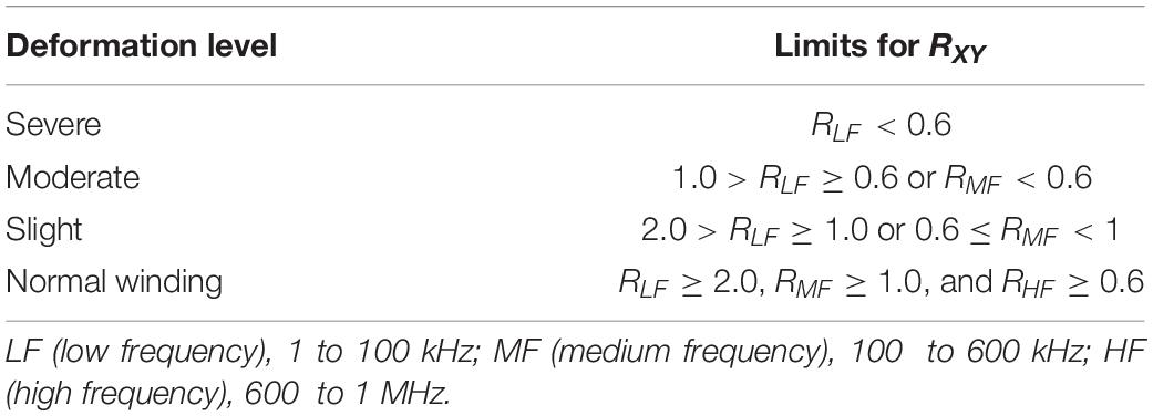
Table 1. Transformer deformation levels and their corresponding RXY values (Wimmer et al., 2007; Kraetge et al., 2008; Bagheri et al., 2013).
Short Circuit Impedance Analysis
The short-circuit impedance (%Z) of power transformers is sometimes measured on-site and it can be compared to the nameplate or factory test values. It is used to detect winding movement that may have occurred since the factory tests were performed. Winding movement usually occurs due to heavy fault current or mechanical damage during transportation or installation. The measurements are usually performed on one phase at a time. Changes of more than ± 3% of the short-circuit impedance should be considered significant (Bagheri et al., 2012a, 2013; IEEE, 2013a).
A convenient method to measure the short-circuit impedance of a transformer is the voltmeter-ammeter method. This method is applicable to testing either single-phase or three-phase transformers. A power source is used to drive a current through the impedance. The current and the voltage across the impedance are measured simultaneously. The impedance is then given by the ratio of the measured voltage and current (IEEE, 2013a).
Figure 1 shows a generic transformer core with concentric type winding. The low voltage winding (secondary winding) is placed near to the core, while it is enclosed by the high voltage winding (primary winding). The primary winding is colored in cyan and the secondary winding is colored in red. Some parameters of these windings are also shown in Figure 1, and they are described below. Physically, the short circuit impedance is extracted as (Bagheri et al., 2012a, b, 2013):
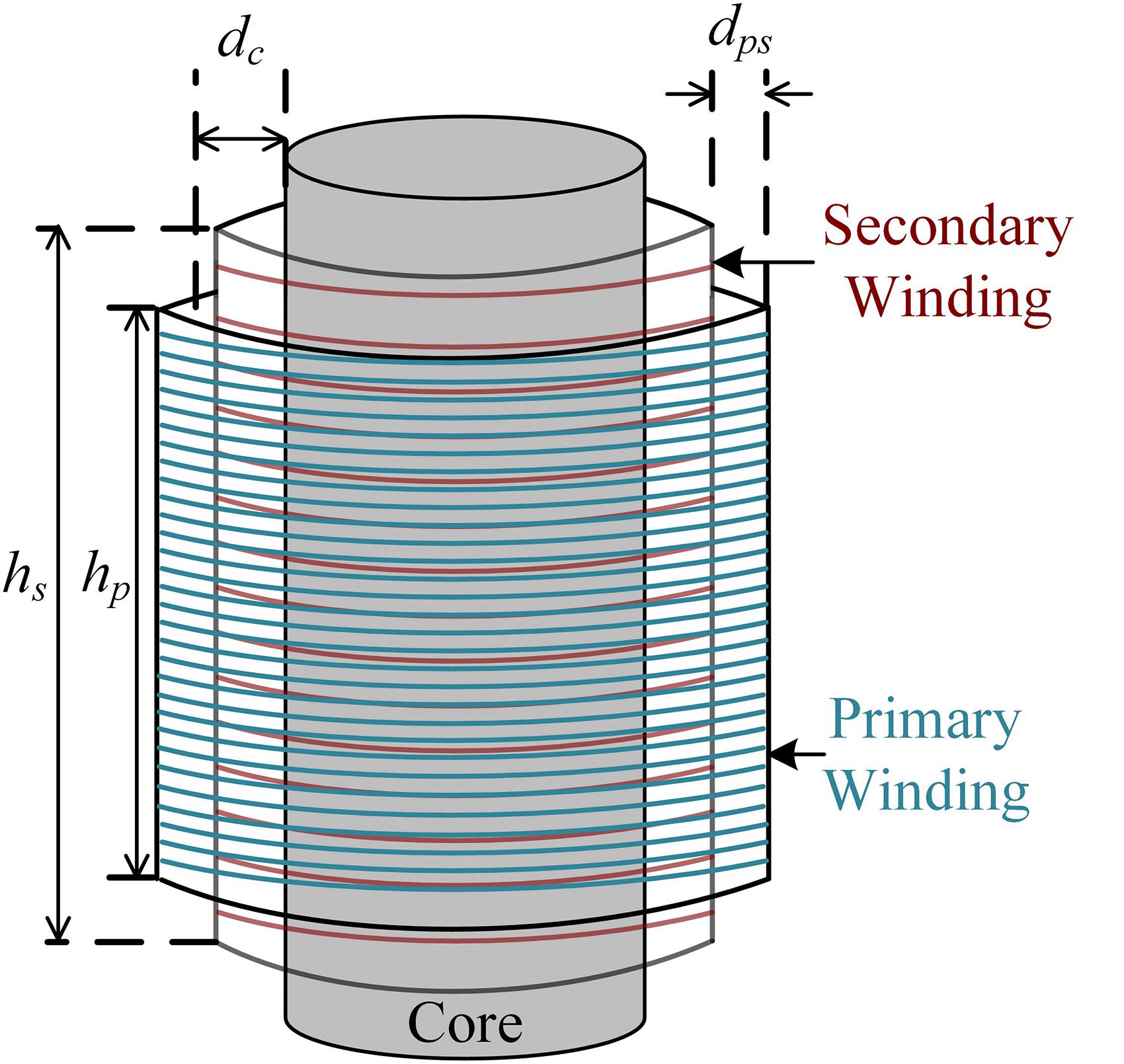
Figure 1. A generic transformer core and its windings.
where dx = dc + (wp-ws)/3, cx = dps + (wp + ws)/3, wp and ws are the width of the primary and secondary side windings (not shown in the figure), respectively, Ps is the short-circuit loss (kW), S is the apparent power (kVA), Ncl is the number of transformer core limbs surrounded by the primary and secondary windings, KR is the Rogowsky efficient, and it is usually assigned to be 1 for most cases (Doebbelin and Lindemann, 2010) with detailed calculation in Jabloński and Napieralska-Juszczak (2007), f is the base frequency, h = (hp + hs)/2, where hp and hs are the height of the primary and secondary side windings, respectively, V/N denotes voltage per turn of the winding. Obviously, the short circuit impedance Zs is a function regarding those geometrical factors such as dc, wp, ws, etc. As winding deformation leads to changes in these factors, the deviation between the value of Zs from short-circuit impedance test results and the fingerprints is able to reveal the winding health status of the transformer.
On-Line Monitoring
Since it is impractical to frequently disconnect transformers and perform off-line condition monitoring, on-line monitoring methods provide promising solutions for low frequency power transformer monitoring. This subsection reviews on-line monitoring techniques for low frequency power transformers.
Short Circuit Impedance Analysis
The on-line short circuit impedance method uses voltage and current measurements from terminals of a transformer to compute its short circuit impedance. Monitoring of leakage inductance of a transformer by using measurements at two different time is investigated in Peng et al. (2006) and Hao et al. (2010). Hu et al. (2011) further improve the method to calculate short circuit impedance (resistance and reactance) of a transformer. In Abu-Siada and Islam (2012), authors construct the ΔV-I locus diagram to provide the current state of a transformer using instantaneous voltage measurements from two terminals of a transformer and current measurements from primary side of the transformer. Masoum et al. (2014) further investigate this technique by considering harmonics, internal fault types, fault levels, etc., and validate this technique by simulation and experimental studies. In Hong et al. (2017), authors collect consecutive instantaneous voltage and current measurement samples from terminals of a transformer and compute its winding resistance and leakage reactance.
A brief introduction for the traditional phasor based on-line short circuit impedance method is illustrated as follows. The on-line short circuit impedance method uses measurements at two different time to compute short circuit impedance of a transformer. The expression for a two-port network as a model for a transformer can be described as follows (Bagheri et al., 2012a):
where V1, V2 are voltages at two ports, I1 and I2 are currents at two ports. By assigning V2 = 0, the short circuit impedance Zsc is expressed as:
Z11, Z12, Z21, Z22 can be computed by using measurements at two different time, i.e., we have:
where t1 and t2 denote two different time. Z11, Z12, Z21, Z22 are computed from equations (12) and (13), and Zsc is then computed.
Transfer Function Method
As shown in Figure 2, as most transformers have capacitive bushings, transformer bushing tap (high voltage side) is suitable for low voltage signal injection as an input point during on-line transfer function measurement (Setayeshmehr et al., 2006, 2009; Bagheri et al., 2012a; Hashemnia et al., 2016). Figure 2 depicts a typical transformer with a bushing tap. The capacitance between the bushing tap and the voltage tap stud is C1, and the capacitance between the bushing tap and the grounded flange is C2. This bushing tap offers a reduced terminal voltage due to the capacitive divider of the bushing (the ratio of C1 to C2 is usually from 1/10 to 1/30). As the capacitive value of the bushing remains relatively constant over a wide frequency range, the actual transformer signature will not be polluted or masked because of the bushing’s own frequency response (De Rybel et al., 2009).
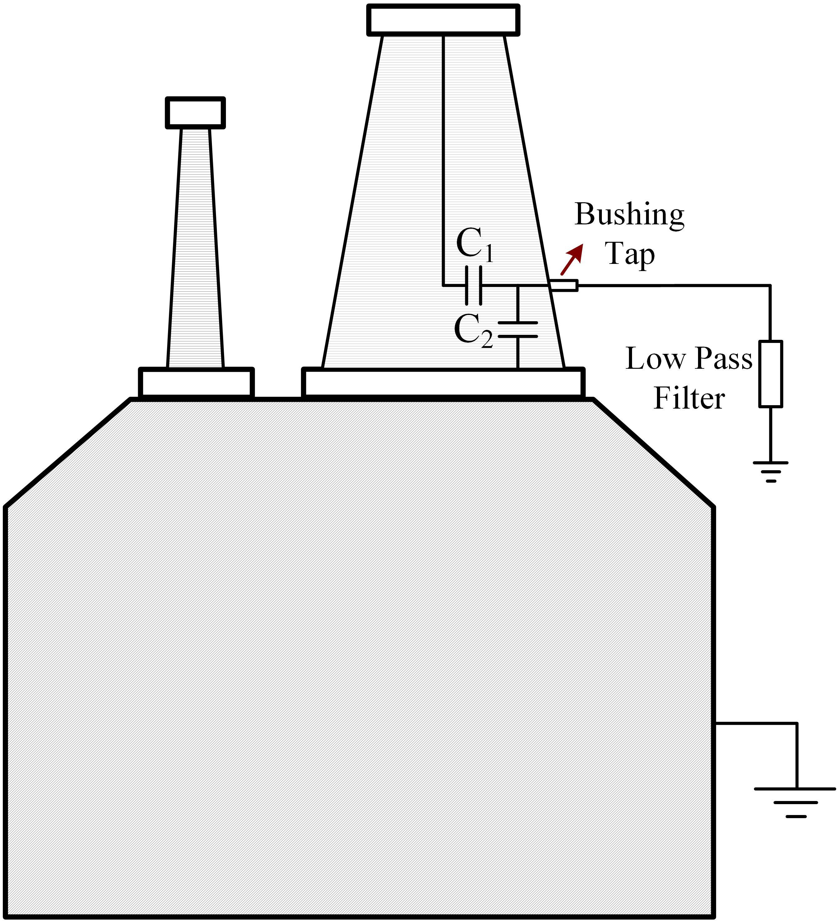
Figure 2. Transformer with bushing tap.
The on-line transfer function method works as follows. During testing, the shorting plug is replaced by an inductor to form a low pass filter as shown in Figure 2. The test signals ranging from 200 kHz to 2.5 MHz are injected to the tap (De Rybel et al., 2009). For the transformer with wye connection, on-line transfer function is measured by a signal injection in phase bushing tap and response is recorded through neutral bushing tap. For the transformer with delta connection, the response is measured between two phases (Bagheri et al., 2012a).
Dissolved Gas Analysis
Dissolved gas analysis (DGA) is a method to distinguish abnormal conditions such as partial discharge, over-heating, arcing in an oil-immersed transformer, as a small amount of insulating oil under these abnormal conditions will be decomposed and generate different types of gas and other chemical compounds (Wang et al., 2002). These degradation products, most of them being gases, are entirely or partially dissolved in the oil, which can be detected by DGA (Duval, 1989). The generated gases can be divided into three groups: (1) hydrogen and hydrocarbons, including hydrogen (H2), methane (CH4), ethylene (C2H4), ethane (C2H6), acetylene (C2H2), etc., (2) carbon oxides, including carbon monoxide (CO), and carbon dioxide (CO2), and (3) non-fault gases, including oxygen (O2), nitrogen (N2), etc. (Hooshmand et al., 2012). Different combinations, ratios, concentrations indicate different types of abnormal conditions (Singh and Bandyopadhyay, 2010). Common schemes of DGA include key gas method, Dornenburg ratio method, Rogers ratio method, nomograph method, IEC ratio method, Duval triangle method, and CIGRE method (Duval, 2003; IEEE, 2009; Sun et al., 2012).
The conventional DGA methods are logic simple. However, different methods may obtain different or conflicting interpretations. As a result, some efforts have been done to optimize the diagnostic techniques. Li et al. (2011) use a multi-step logic for DGA. The results show a superior performance compared with Duval triangle method. Jakob et al. (2012) propose an energy weighted DGA to evaluate the severeness of transformer faults by assigning different weights to the concentrations of different gases. In addition, some research has been done by applying fuzzy logic and artificial intelligence to improve the accuracy of DGA interpretation. For instance, Qian et al. (2009) propose a synthetic diagnosis approach including neural network and fuzzy theory to analyze DGA data. Ghoneim et al. (2016) apply artificial neural networks (ANN) in DGA to enhance the fault diagnosis. Khan et al. (2015) compare the performance between fuzzy logic based DGA and adaptive neuro fuzzy inference system (a hybrid learning rule derived from ANN and fuzzy logic), and better results are obtained from the latter technique. Wani et al. (2017) integrate Duval triangle method and IEC ratio method together and apply fuzzy logic with the concept of energy weighing to evaluate the fault type and severity of the fault. Wani et al. (2019) further integrate Rogers ratio method and propose a fault interpretation matrix that resolves the issue of contradictory decisions from different methods.
On-Line Partial Discharge Testing
Partial discharge generates low-amplitude (in the milliampere range), short-duration (in microsecond range or even below) current pulses (IEEE, 2013a). Based on these two characteristics, two commonly used partial discharge detection methods are developed: (1) Detection of acoustic signals, and (2) Measuring electrical quantities generated from partial discharge (Wang et al., 2002). For the first method, multiple (three or more) piezoelectric ultrasonic sensors are required to be installed on the transformer tank in order to capture pulses generated from partial discharge. By recording time of arrival of the pulse from each sensor and the time difference of pulse arrival between each sensor, the partial discharge can be detected, and its location can be identified (Judd et al., 2005; Ramírez-Niño and Pascacio, 2009; IEEE, 2019a). Sinaga et al. (2012) describe and compare three ways to determine the time difference of pulse arrivals from different sensors. Specifically, the time difference of pulse arrivals can be determined by (1) the time difference of the first peak from different sensors, (2) analysing the cross-correlation between signals from different sensors, and (3) examining the cumulative energy of the signals. The results show the highest accuracy is obtained from the first way of determining the signal arrival time.
The second method is to measure electrical quantities generated from partial discharge by a partial discharge detector. The basic idea is to detect the high-frequency low-amplitude disturbances on the applied voltage and current waveform by measuring the applied waveform (Wang et al., 2002). Electrical partial discharge signals are usually measured from the bushing tap. According to IEEE (2010), three major circuit components are required: (1) Coupling unit, which captures the partial discharge signals from the terminals of the monitored transformer, (2) measuring instrument, which processes the captured partial discharge signals and evaluates the apparent charge level, and (3) associated high-voltage and low-voltage leads and measuring cables. An example of partial discharge measuring circuit is depicted in Figure 3, where a coupling unit (measuring impedance), a measuring instrument, and measuring cables are shown. The coupling unit, usually containing a measuring impedance and a coupling capacitor, serves as a high-pass filter that filters out the low-frequency test signals and transfers the high-frequency partial discharge signals to the partial discharge measuring instrument through the cable (IEEE, 2013a). Note that if the measuring circuit is connected to the capacitive-graded bushing as shown in Figure 3, the capacitance C1 (shown in Figure 3) may substitute the coupling capacitor in the coupling unit (i.e., no coupling capacitor is required in the coupling unit).
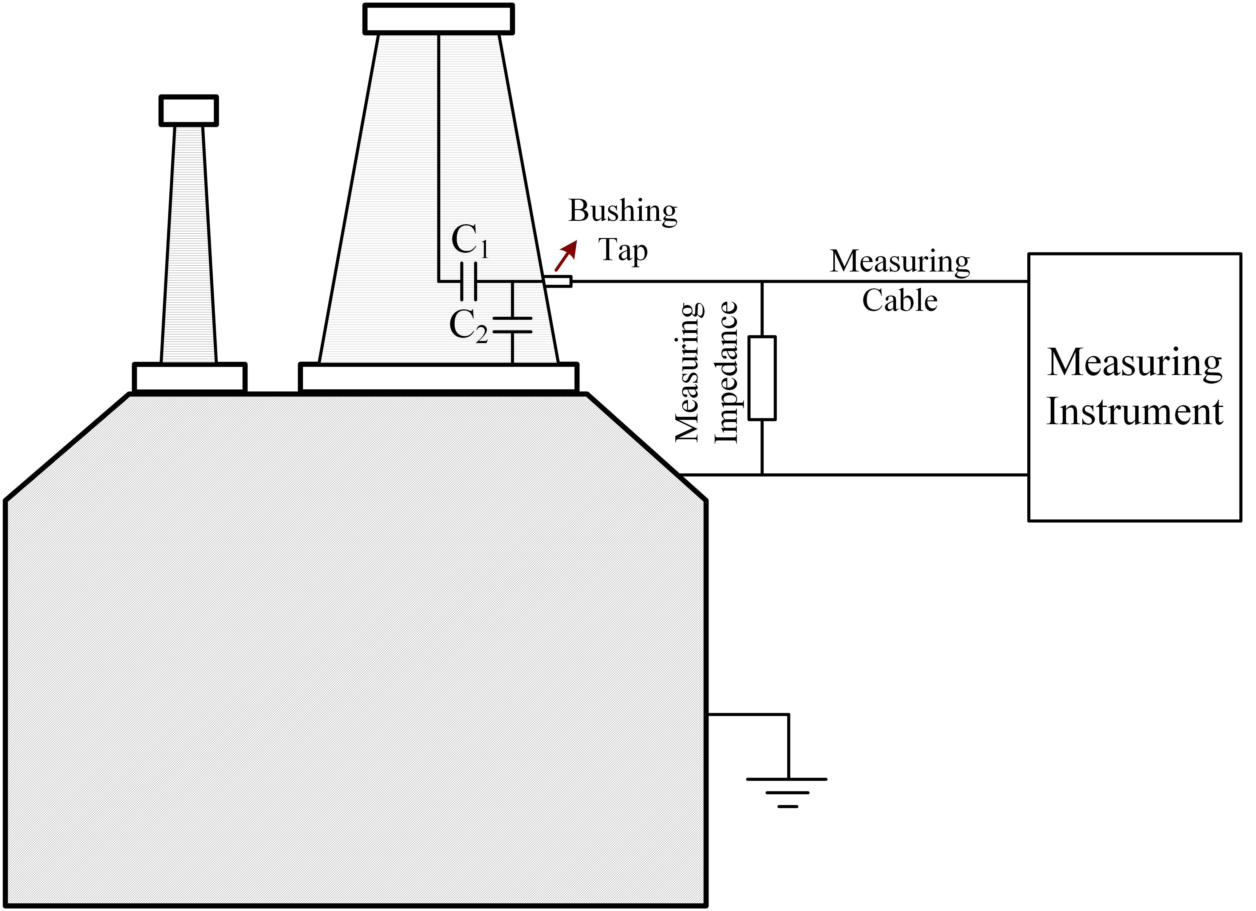
Figure 3. An example of partial discharge measuring circuit.
Other Methods
Vibration Method
Vibration monitoring is introduced as an on-line monitoring method in García et al. (2005c). Studies show that the transformer tank vibration depends on voltage square and current square. The main harmonic of the vibration is 100Hz and its multiples if the base frequency is 50Hz (García et al., 2005a, b). An example in García et al. (2005b) tests the vibration method on a healthy transformer and a winding deformed transformer, and noticeable harmonics differences are captured between these two transformers. Therefore, the vibration method is considered to be one of on-line monitoring methods, especially for the monitoring of transformer’s winding deformation. However, since the vibration method is derived from the mathematical model considering critical parameters of the transformer, the performance of the vibration method could also be affected by some other external factors. In addition, as any part/accessory of a transformer could contribute to the vibration harmonics, and the vibration test could also be affected by the dynamics in the transformer from the grid, the interpretation of the vibration test results is difficult (Bagheri et al., 2012a).
Current Deformation Coefficient Method
This method superimposes a high frequency sinusoidal voltage on the power frequency voltage across the monitored winding. Unlike the transfer function method, high frequency components of the currents at line-end and neutral-end of the monitored winding are measured using isolated precision current probes and a digital filtering technique. Note that since the imposed high frequency voltage is maintained constant, fingerprint measurements are first obtained when the winding is healthy. Current Deviation Coefficient (CDC), derived based on the measurements, is used as an effective indicator of deformation. CDC is calculated as follows:
where I1H and I2H are fingerprint values of measured terminal currents (line-end and neutral-end) at the selected high frequency, and and are terminal current values after deformation (Joshi and Kulkarni, 2010).
Communication Method
Communication method (Akhavanhejazi et al., 2011) is applied to detect transformer winding axial displacement based on scattering parameters. An antenna, placing inside or outside the tank, works both transmitting and receiving modes. The reflected wave from the inside of the transformer is received by the antenna, and the scattering parameter is computed as: , where Prec is the receiving power of the antenna, and Pin is the transmitting power. The measured scattering parameter is then compared with the fingerprint (the reference scattering parameter) as to detect winding axial displacement.
Protection of Low Frequency Transformers
The prevailing protection schemes applied in industry for protection of low frequency transformers include but are not limited to over-current protection, differential protection, volts per hertz protection, and thermal protection, etc. These protection schemes need a large amount of settings, and they need to coordinate with each other. All of these protection schemes constitute the whole protection scheme for a transformer. This section first introduces these prevailing protection schemes in industry, follows some other promising protection schemes under development.
Over-Current Protection
Transformer over-current protection uses fuses or over-current or directional over-current relays to achieve its protection scheme. A specific over-current protection scheme depends on the interrupting devices (i.e., breakers, fuses, etc.), enabling the protected transformer to disconnect from the grid. The response of the time of over-current relays is expressed with analytical equations (IEEE, 2019b):
where M is the multiples of pickup current (Iinput/Ipickup, Ipichup is the relay current set point), A, B, p are constants chosen to provide the selected curve characteristics of the analytical equation. Over-current protection is a straightforward protection scheme. However, it is only able to detect some significant faults that cause high currents. As a result, it is not able to detect faults that cause relatively small changes in currents, such as inter-turn faults. In addition, it may mis-operate during transformer energization, since high-magnitude inrush currents occur in this condition.
Differential Protection
Differential protection is the most widely applied protection scheme for low frequency transformer protection, and it is able to detect internal faults such as short circuit between windings. A typical differential protection for a single-phase transformer is shown in Figure 4, where two current transformers (CTs) are installed at the two terminals of the protected transformer. The differential relay processes the data from CTs and performs the protection logic. Considering the transformer turn ratio to be N1:N2, the ratios of two CTs to be 1:N1 and 1:N2, and currents from two terminals as I1 and I2. The basic idea of the differential protection is to apply Kirchhoff’s current law and compute the sum of the currents (N1I1 − N2I2) flowing into the transformer from the two terminals. Since the ratio between currents from the two terminals is approximately equal to the turn ratio of the transformer, the sum of the currents is at a very low value during normal operation, while it will be a high value when an internal fault occurs. This is used as an indicator of an internal fault of the transformer. However, because of variable taps in the transformer and the instrumentation errors, the sum of the currents is not strictly equal to zero in practical cases. To solve this problem, percentage differential relays are developed. This kind of relays add a restraining quantity IR, and the trip logic is modified as (IEEE, 2008):
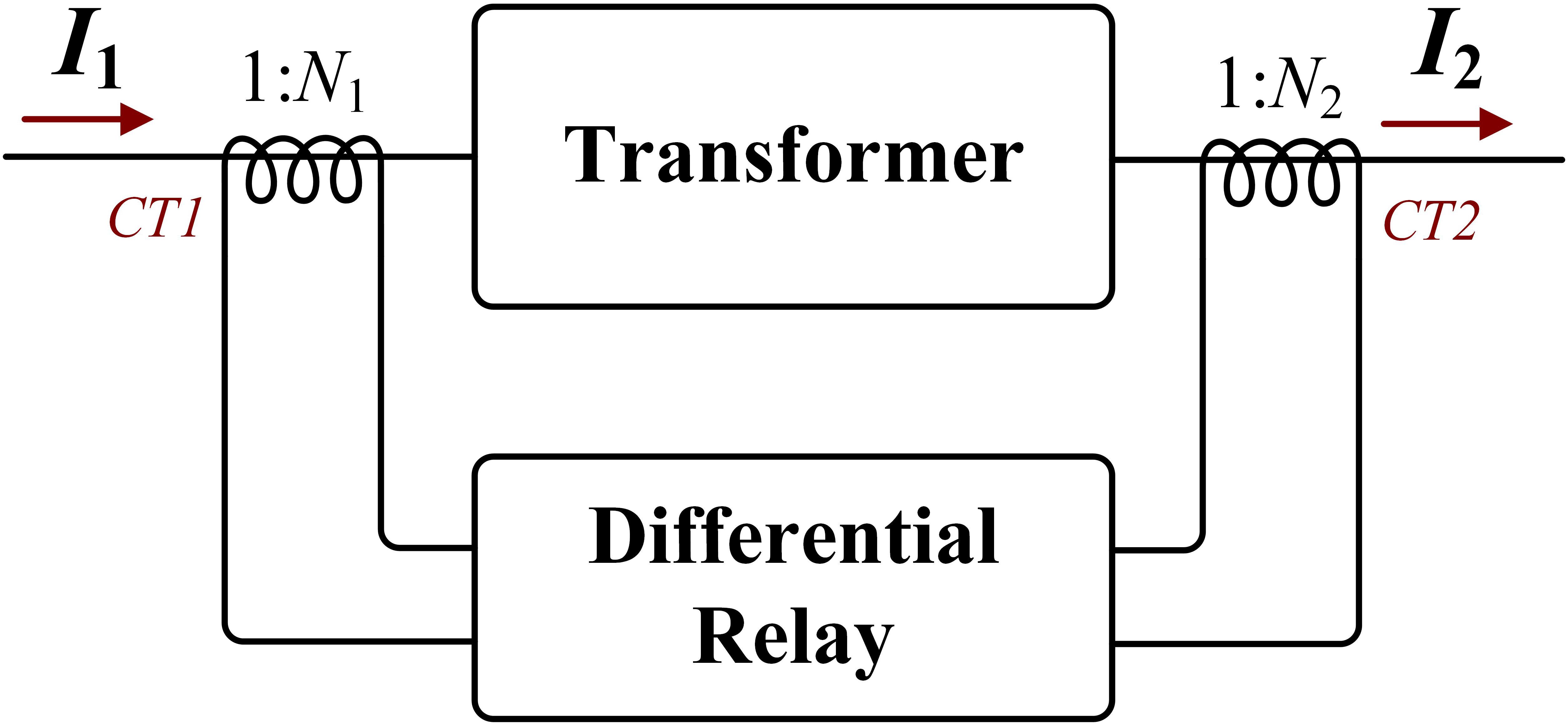
Figure 4. A typical differential relay protection for a single-phase transformer.
where Io = N1I1-N2I2. Different alternatives are used to represent IR, one of them is: IR = k|N1I1 + N2I2|, where k is a constant.
Additional restraints such as harmonic restraints are added to the differential protection to avoid undesired tripping due to the inrush currents when a transformer is energized. A typical trip logic is (IEEE, 2008):
where Ih2, Ih3, … are the second-, third-, and higher harmonic components of the operating current, k2, k3, … are constants of proportionality, s is the slope of the percentage differential characteristics. The second-harmonic restraint method, which checks if the ratio between the second-harmonic component and the operating current is over a set point, is the most common one (Hamilton, 2013), and it is developed based on the studies indicating the second-harmonic component in inrush current is much higher than that from a fault current (Fan et al., 2015). Negative sequence differential protection is another kind of differential protection that protects inter-turn faults (Kasztenny et al., 2015), as the regular differential protection is not able to detect this kind of faults.
Volts per Hertz Protection
Low frequency transformers are designed to operate near the saturation knee of the core during the normal operation. As the magnetic flux is proportional to the voltage and inversely proportional to the frequency (Guzman et al., 2001), any situations impacting voltage and frequency of the transformer such as voltage increase, frequency decrease, increase of the ratio of voltage over frequency lead to saturable core, which generates excessive heat and results in temperature rise in the transformer and eventually transformer failure. Overexcitation, the major situation for this protection scheme, can damage the transformer without any intervention. Specifically, overexcitation leads to excessive core flux because of saturable core, which results in iron burning. In addition, as the normal magnetic iron path saturates, the flux starts to flow through leakage paths that are not designed to carry it, and cause damage (Mozina, 2011). A typical volts per hertz relay is with an inverse characteristic, similar as the characteristic curve of an over-current relay (IEEE, 2004). As this protection scheme is mainly for overexcitation situation, it is limited in under-excitation condition. Apparently, additional protection schemes are required to coordinate this protection scheme.
Thermal Protection
Transformers may overheat due to the high ambient temperatures, failure of cooling system, external fault not cleared promptly, overload, abnormal system conditions such as low frequency, high voltage, non-sinusoidal load current, and phasor-voltage unbalance, etc. (IEEE, 2008). The overheat deteriorates insulation life of a transformer and may also release gas bubbles that lower the dielectric strength of the oil. Presently, several methods for monitoring transformers are available to help protect against thermal overload and failure. Some commonly used devices are: Oil and embedded temperature sensors, liquid over-temperature detectors, winding over-temperature detectors, gas accumulation relays, etc. (Swift et al., 2001). Thermal protection is also straightforward, but it may react too late since it needs the occurrence of the overheat condition.
Communication Assisted Protection
With advanced communication protocols (IEC 61850) and high-sampling rate data acquisition systems such as merging units, communication assisted protection of transformer is also evolving. Merging units collect data from CT/PT (potential transformer) and transmit high-sampling rate GPS-synchronized sampled value data through ethernet network via IEC 61850-9-2 (Aftab et al., 2020). The introduction of such data acquisition systems separates the data processing part from traditional relays, and as a result, more freedom is provided to analyze the collected data. Ingram et al. (2013) test and validate transformer differential protection with merging units and IEC 61850 protocol. Gaouda et al. (2016) test merging units communicating with SCADA system over ethernet and WiFi-5 GHz links. Furthermore, the authors in this paper also demonstrate that merging units can also operate standalone and report limited situational awareness features with the high-sampling rate data. Other communication methods that assist monitoring and protection of transformers are also introduced in the literature. For instance, the authors in Duong et al. (2019) introduce a meter data management system that collects the operating parameters of distribution transformers from IEDs via 3G modem.
Other Protection Schemes
Wavelet-Based Protection
Wavelet-based differential protection scheme is one of the promising options for power transformer protection. The wavelet decomposition breaks up the energy of the signals into both time and frequency, allowing for a more complete and efficient description of each signal. By selecting good mother wavelet, this method emphasizes the difference between fault and inrush currents, since their energy distribution in time and frequency is different (Gomez-Morante and Nicoletti, 1999). Saleh and Rahman (2005) propose a two-level resolution wavelet packet transform that extracts certain features of the differential currents to distinguish between the magnetizing inrush currents and different internal fault currents. Medeiros and Costa (2017) further add external faults detection and CT saturation modules in their wavelet-based protection schemes to block tripping during external faults but trip the protected transformer during the internal faults or cross-country faults (an external fault close to the protected transformer followed by an internal fault). However, the performance of wavelet-based methods is dependent upon mother wavelet selections and in general these methods require much more development to understand their performance in transformer protection.
Dynamic State Estimation Based Protection
Dynamic state estimation based protection utilizes all the available measurements and considers full dynamics in the transformer by checking whether these redundant measurements are consistent with the dynamic model of the protected transformer. High sampling rate measurement sensors (e.g., merging unit, etc.) are used to capture full dynamics in the protected transformer in this protection scheme. Fan et al. (2015) and Meliopoulos et al. (2016) apply a dynamic state estimation technique (Liu et al., 2020) on transformer protection and compare the performance of this technique with other traditional protection schemes. Their results show that this technique is able to prevent mis-operations caused by harmonics and inrush currents when the transformer is energized. In Vasios et al. (2019), a transformer with saturable core case is further investigated to demonstrate the effectiveness of the proposed dynamic state estimation based protection scheme. The results in Vasios et al. (2019) indicate that the proposed protection scheme is able to ignore external faults and identify internal faults. In addition, a cross-country fault is also tested in this paper, and the dynamic state estimation based protection does not trip for the external fault while maintaining its ability to detect any internal faults that may happen. Xie et al. (2019) investigates the application of dynamic state estimation on the unit protection, i.e., a protection zone containing multiple devices. A transformer-and-cable unit is demonstrated as an example. The protection algorithm in this paper is able to not only detect internal faults and ignore external faults but identify the faulted component in the protected unit as well. However, this type of method needs high-fidelity model of the protected transformer. More experimental tests are needed to substantiate its effectiveness.
Artificial Intelligence-Based Protection
Artificial intelligence-based methods such as ANN are also attempted in transformer protection. An ANN is a mathematical model that is based on the architecture and functionality of biological neural networks. The element building unit of an ANN is the neuron. The ANN is formulated by organizing a number of neurons in several layers. For instance, an ANN based adaptive differential relay is proposed in Ahmad et al. (2019). The ANN is trained to adapt the energization situation so that the proposed relay will not mis-operate during the energization. Afrasiabi et al. (2019) integrate an accelerated convolutional neural network into transformer differential protection, which discriminates internal faults from energization condition. Bagheri et al. (2017) use wavelet transform technique to extract the features from differential current data and then train the decision tree classifiers and ANN by these extracted feature data. The proposed algorithm aims to classify winding mechanical defects, electrical faults, and inrush currents in a good precision. However, the artificial intelligence-based methods usually need a large dataset for training. And such dataset may not cover all the cases of transformer protection. In general, more experimental tests or field tests are needed to prove the effectiveness of this type of method.
Protection of Solid-State Transformers
The concept of SST was discussed starting from 1970s (Brooks, 1980). Together with the demand of integrating renewable energy resources into distribution systems and the constantly progress in power electronics technology, SSTs are considered as promising options for interfacing between different voltage levels, usually between medium voltage level and low voltage level, in power systems. As shown in Figure 5, an SST consists of an AC to DC converter, a DC to AC converter, and a DC to DC dual active bridge containing a high frequency transformer. SST transforms voltages between low frequency interfaces via this high frequency transformer, and as a result, its volume and weight are reduced significantly (She et al., 2013; Huang, 2016). As power systems are constantly subject to perturbations, the protection techniques for SSTs need to be investigated. This section reviews conventional and power electronics-based technology for the protection of SSTs.
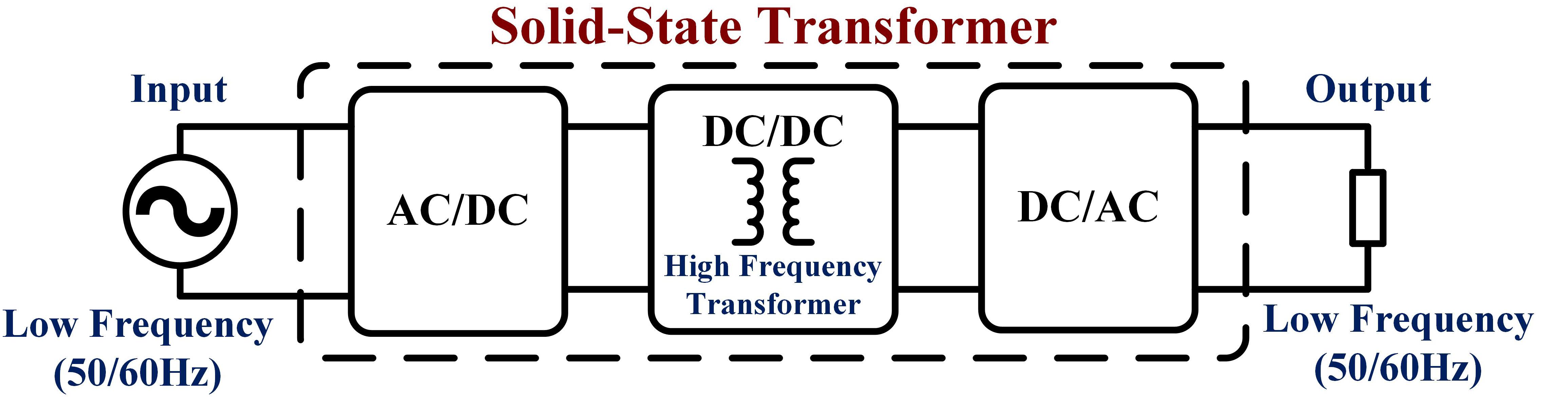
Figure 5. Topology of solid-state transformer.
With the Aid of Conventional Protective Devices
This subsection introduces the protection of SSTs using conventional protective devices such as breakers, fuses, metal-oxide surge arresters, etc.
Over-Current Protection
For an SST, the typical maximum allowable over-current ratios are in the range of 1.5 × for some minutes and 4 × for some milliseconds. Because of such characteristics, fuses/breaker combinations are used on both sides of an SST for interrupting phase currents (Madhusoodhanan et al., 2013; Guillod et al., 2016). As the SST has limited overcurrent capability (Carr et al., 2013; Madhusoodhanan et al., 2013), breakers are required at medium voltage side (primary side) to disconnect the SST after a medium voltage side short circuit or an internal failure. Fuses act as the final backup for protection (Guillod et al., 2016). One obvious drawback of the fuse protection is that it is a one-time over-current protection. In Karady and Liu (2010), authors claim that the internal sensors in the SST are able to shut down the converter by removing the gate signals in case of an internal fault (over-current). A typical over-current protection threshold is 1.8–2 times the rated current.
Over-Voltage Protection
For over-voltage protection, metal-oxide surge arresters can be arranged to clamp large over-voltage at both medium voltage side and low voltage side. Metal-oxide surge arresters are able to divert large line over-voltage to ground through a low-impedance path (Madhusoodhanan et al., 2013). As the SST has limited over-voltage capability (Carr et al., 2013), surge arresters are also recommended to be placed between the phases in order to achieve better clamping (Guillod et al., 2016). Note that metal-oxide surge arresters are traditional methods to clamp over-voltage, other advanced devices for over-voltage protection are introduced in section “With the Aid of Advanced Protective Devices.” In addition, some literature also introduces the over-voltage protection for the dc bus voltage of each module in the modular SST. The over-voltage protection can shut down individual modules and send fault signals to the digital signal processor for system level shut down (Lai et al., 2017). Anurag et al. (2018) introduce protection and deadtime generation board for over-voltage or over-current protection. This protection scheme lowers the PWM signals as soon as a fault is detected. Apparently, over-voltage protection should be coordinated with other protection schemes to protect SSTs.
Under-Voltage Protection
The design of under-voltage protection scheme can be integrated within the SST. In Karady and Liu (2010) and Tatcho et al. (2012), the under-voltage protection scheme is executed by blocking the IGBTs in the rectifier of the SST, so that the SST is disconnected to the grid when its primary voltage falls under a threshold value (e.g., 0.8 p.u.). The under-voltage protection of SSTs takes into effect when a fault occurs on the line resulting a voltage drop. It can also serve as backup protection for the internal fault of SST. Similar as over-voltage protection, this protection scheme should be coordinated with other protections schemes to protect SSTs.
With the Aid of Power Electronics-Based Protective Devices
This subsection introduces the protection of SSTs using power electronics-based protective devices such as solid-state breaker, solid-state current limiter, etc. (Guillod et al., 2016).
Solid-State Breaker
Solid-state breaker, i.e., power electronics-based breaker is one of the options that immediately disconnect the SST from the medium voltage grid during severe disturbances such as short circuit faults. Specifically, a fast-acting semiconductor AC switch containing IGBT switches and diodes is installed between the fuse and the AC to DC rectifier (Meyer et al., 2004; Vodyakho et al., 2011; Madhusoodhanan et al., 2013). During the normal operation, the gate signals to the IGBTs are high and the breaker is “closed.” When the fault occurs, with the help of current sensors installed in the breaker, the high fault current is detected and the gate signals to the IGBTs are turned low to break the entire circuit (i.e., the breaker is “open”).
Fast acting semiconductor switches are also placed on the positive and negative terminals of the DC bus for the purpose of protecting the converter in case of faults occurring on the DC side of the AC to DC converter. These switches will open up and protect the converter IGBTs and diodes from the fault currents in case of DC bus fault (Madhusoodhanan et al., 2013; Wang et al., 2019). In summary, solid-state breakers perform as circuit breakers with a faster response in the protection scheme. However, solid-state breakers have their own drawbacks. For example, solid-state breakers have higher energy loss and higher cost. Besides, the design of a protection scheme including solid-state breakers is more complicated.
Solid-State Current Limiter
The objective of a solid-state current limiter is to lower the fault current by increasing the short circuit impedance during a fault. A solid-state current limiter can be installed at the medium voltage level of the grid and can be considered as an electronic switch with a varistor. During normal operation, the loss of currents flowing through the switch is negligible. When a fault occurs, the current limiter blocks the switch, and the fault currents flow through a high impedance (varistor). The fault currents are much lower than the short-circuit current with the current limiter (Abramovitz and Smedley, 2012). Some other current limiters are connected in parallel to the solid-state circuit breaker. For example, in Meyer et al. (2004), a current limiter consists of a simple inductance, a capacitance or a parallel LC-circuit. Once a short circuit fault is detected, the solid-state breaker opens immediately (<100 microseconds). In the meantime, the currents continue to flow by going through the solid-state current limiter containing reactive elements. The current level through the current limiter is chosen to be higher than the nominal current of this part of the grid but also significantly lower than the short-circuit current, so that the remaining part of the grid will not experience severe disturbances. Since the purpose of the solid-state current limiter is to lower the fault current, other protection schemes are needed in order to remove the fault or isolate the faulted component.
Transient Voltage Suppression
Transient voltage suppression (TVS) diodes or DC brake choppers can be used to clamp the DC-link voltages. In Guo et al. (2014), a diode bridge connecting to both AC side and DC side of the rectifier is proposed. Under normal operation, diodes in the diode bridge carry only some leakage current. During an over-voltage fault, the TVS diodes switch on (less than 50 ns) and clamp the over-voltage to protect the device. The DC brake chopper is a simple protection device that shorts the DC-link through a power resistor when the DC-link voltage exceeds a fixed threshold (Schoening et al., 2011; Pannell et al., 2013). However, although the over-voltage at the DC-link is limited by this type of solution, the inrush currents through the ac-dc converters are increased (Guillod et al., 2016). Similar as solid-state current limiters, other protection schemes are needed in order to remove the fault or isolate the faulted component.
Summary
This paper reviews the state-of-art monitoring and protection technology for transformers in dynamic power systems. The monitoring of low frequency transformers, protection of low frequency transformers, and protection of SSTs are reviewed in separate sections. In the section of monitoring low frequency transformers, since the off-line monitoring technique is quite mature, two major off-line monitoring methods are introduced. As the on-line monitoring methods are still under development, different on-line monitoring methods are introduced. The methods of monitoring low frequency transformer are summarized in Table 2.
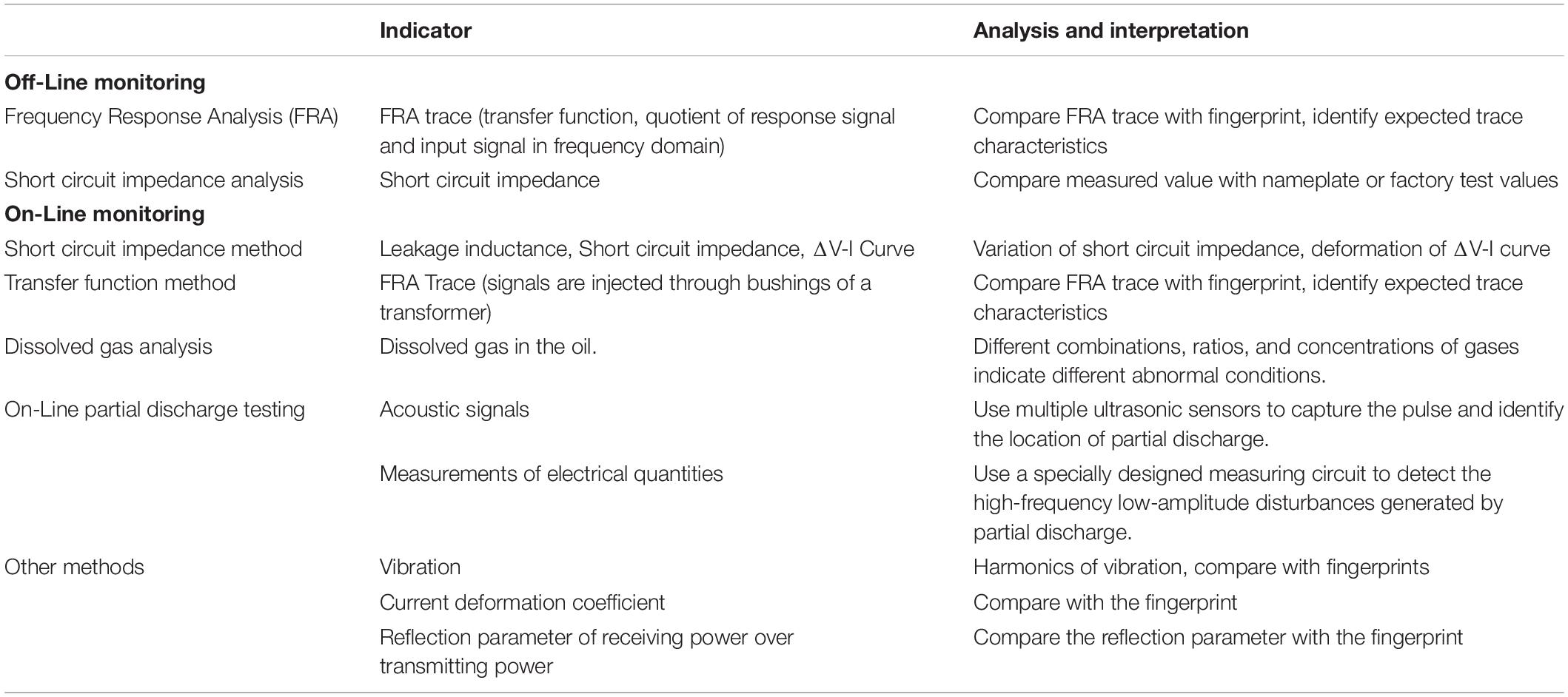
Table 2. Summary of monitoring low frequency power transformers.
In the section of low frequency transformer protection, some prevailing protection schemes (over-current protection, differential protection, volts per hertz protection, and thermal protection, etc.) in industry are first introduced. Among these protection schemes, differential protection is the most popular one. However, each of these protection schemes has their own shortcomings as described in section “Protection of Low Frequency Transformers.” These protection schemes also need to coordinate with each other, and a large number of settings are required. The advanced communication protocols and high-sampling rate data acquisition systems provide more freedom to analyze the collected data and protect the transformer. In addition, some other promising protection schemes under research are also introduced in this paper. The protection schemes for low frequency transformers are summarized in Table 3.
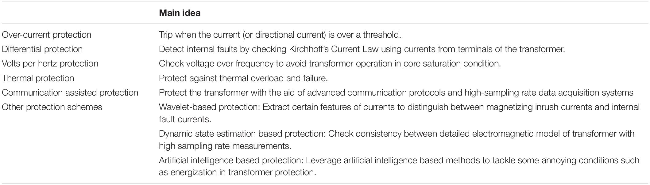
Table 3. Summary of protection of low frequency power transformers.
Since the architecture of SST is totally different from the conventional low frequency transformer, the protection of SST is reviewed in a separate section (section “Protection of Solid-State Transformers”). The protection schemes of SSTs are still under development, and section “Protection of Solid-State Transformers” divides the protection schemes into two categories: (1) With the aid of traditional protective devices, and (2) with the aid of power electronics-based protective devices. The protection schemes in the literature need to coordinate with each other, and they constitute the whole protection scheme for SSTs. In addition, for those power electronics-based protective devices, their complexity, higher energy loss, and higher cost should also be considered. The protection schemes of SSTs are summarized in Table 4.
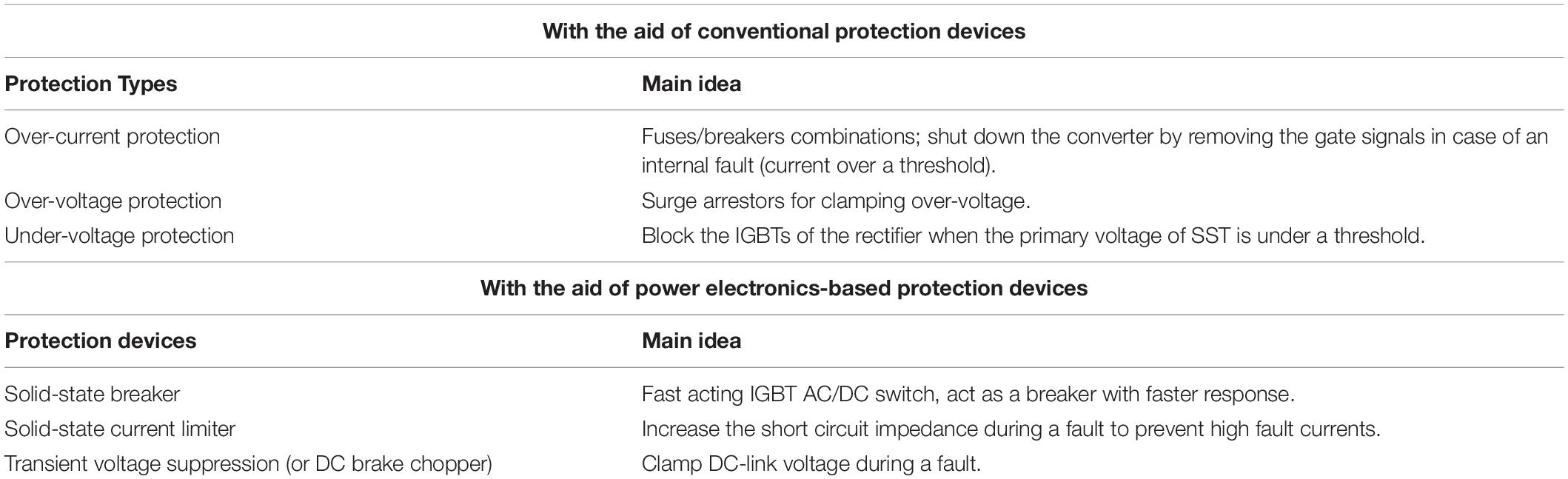
Table 4. Summary of protection of solid-state transformers.
Author Contributions
BX wrote the original draft. DZ and TH provided the supervision, review, and editing of the draft. All authors contributed to the article and approved the submitted version.
Funding
This work was supported by the U.S. Department of Energy, Office of Electricity.
Conflict of Interest
The authors declare that the research was conducted in the absence of any commercial or financial relationships that could be construed as a potential conflict of interest.
Acknowledgments
The support from U.S. Department of Energy is greatly appreciated.
References
Abeywickrama, K. N. B., Serdyuk, Y. V., and Gubanski, S. M. (2006). Exploring possibilities for characterization of power transformer insulation by frequency response analysis (FRA). IEEE Trans. Power Deliv. 21, 1375–1382.
Abramovitz, A., and Smedley, M. (2012). Survey of solid-state fault current limiters. IEEE Trans. Power Electron. 27, 2770–2782. doi: 10.1109/tpel.2011.2174804
Abu-Siada, A., and Islam, S. (2012). A novel online technique to detect power transformer winding faults. IEEE Trans. Power Deliv. 27, 849–857. doi: 10.1109/tpwrd.2011.2180932
Afrasiabi, S., Afrasiabi, M., Parang, B., and Mohammadi, M. (2019). Integration of accelerated deep neural network into power transformer differential protection. IEEE Trans. Ind. Inform. 16, 865–876. doi: 10.1109/TII.2019.2929744
Aftab, M. A., Hussain, S. S., Ali, I., and Ustun, T. S. (2020). IEC 61850 based substation automation system: a survey. Int. J. Electr. Power Energy Syst. 120:106008. doi: 10.1016/j.ijepes.2020.106008
Ahmad, A., Othman, M. L., Zainab, K. K. B., and Hizam, H. (2019). Adaptive ANN based differential protective relay for reliable power transformer protection operation during energisation. IAES Int. J. Artif. Intellig. 8, 307–316. doi: 10.11591/ijai.v8.i4
Akhavanhejazi, M., Gharehpetian, G. B., Faraji-Dana, R., Moradi, G. R., Mohammadi, M., and Alehoseini, H. A. (2011). A new on-line monitoring method of transformer winding axial displacement based on measurement of scattering parameters and decision tree. Expert Syst. Appl. 38, 8886–8893. doi: 10.1016/j.eswa.2011.01.100
Anurag, A., Acharya, S., Prabowo, Y., Jakka, V., and Bhattacharya, S. (2018). “Mobile utility support equipment based solid state transformer (MUSE-SST) for MV grid interconnection with Gen3 10 kV SiC MOSFETs,” in Proceedings of the 2018 IEEE Energy Conversion Congress and Exposition (ECCE), Portland, OR, 450–457.
Bagheri, M., Naderi, M. S., and Blackburn, T. (2012a). Advanced transformer winding deformation diagnosis: moving from off-line to on-line. IEEE Trans. Dielectr. Electr. Insulat. 19, 1860–1870. doi: 10.1109/tdei.2012.6396941
Bagheri, M., Naderi, M. S., Blackburn, T., and Phung, T. (2012b). “FRA vs. short circuit impedance measurement in detection of mechanical defects within large power transformer,” in Proceedings of the 2012 IEEE International Symposium on Electrical Insulation, San Juan, PR, 301–305.
Bagheri, M., Naderi, M. S., Blackburn, T., and Phung, T. (2013). Frequency response analysis and short-circuit impedance measurement in detection of winding deformation within power transformers. IEEE Electr. Insulat. Magazine 29, 33–40. doi: 10.1109/mei.2013.6507412
Bagheri, S., Moravej, Z., and Gharehpetian, G. B. (2017). Classification and discrimination among winding mechanical defects, internal and external electrical faults, and inrush current of transformer. IEEE Trans. Ind. Inform. 14, 484–493. doi: 10.1109/TII.2017.2720691
Brooks, J. L. (1980). Solid State Transformer Concept Development (No. CEL-TN-1575). Hueneme, CA: CIVIL Engineering Lab (Navy) Port.
Carr, J., Wang, Z., Bhattacharya, S., Hatua, K., and Madhusoodhanan, S. (2013). “Overloading and overvoltage evaluation of a transformerless intelligent power substation,” in Proceedings of the 2013 IEEE Power & Energy Society General Meeting, Vancouver, BC, 1–5.
Christian, J., and Feser, K. (2004). Procedures for detecting winding displacements in power transformers by the transfer function method. IEEE Trans. Power Deliv. 19, 214–220. doi: 10.1109/tpwrd.2003.820221
De Rybel, T., Singh, A., Vandermaar, J. A., Wang, M., Marti, J. R., and Srivastava, K. D. (2009). Apparatus for online power transformer winding monitoring using bushing tap injection. IEEE Trans. Power Deliv. 24, 996–1003. doi: 10.1109/tpwrd.2009.2022674
Doebbelin, R., and Lindemann, A. (2010). Leakage inductance determination for transformers with interleaving of windings. PIERS Online 6, 527–531. doi: 10.2529/PIERS091220093021
Duong, M. Q., Sava, G. N., Ha, T. V., and Le, T. M. C. (2019). “Automatic tool for transformer operation monitoring in smartgrid,” in Proceedings of the 2019 11th International Symposium on Advanced Topics in Electrical Engineering (ATEE), Bucharest, 1–6.
Duval, M. (1989). Dissolved gas analysis: it can save your transformer. IEEE Electr. Insulat. Magazine 5, 22–27. doi: 10.1109/57.44605
Duval, M. (2003). New techniques for dissolved gas-in-oil analysis. IEEE Electr. Insulat. Magazine 19, 6–15. doi: 10.1109/MEI.2003.1192031
Fan, R., Meliopoulos, A. S., Cokkinides, G. J., Sun, L., and Liu, Y. (2015). “Dynamic state estimation-based protection of power transformers,” in Proceedings of the 2015 IEEE Power & Energy Society General Meeting, (Piscataway, NJ: IEEE), 1–5.
Federal Energy and Regulatory Commission (2018). Distributed Energy Resources Technical Considerations for the Bulk Power System. Toronto: Energy Transformation Network of Ontario.
Gaouda, A. M., Abdrabou, A., Shaban, K. B., Khairalla, M., Abdrabou, A. M., El Shatshat, R., et al. (2016). A smart IEC 61850 merging unit for impending fault detection in transformers. IEEE Trans. Smart Grid 9, 1812–1821. doi: 10.1109/TSG.2016.2600680
García, B., Burgos, J. C., and Alonso, Á. M. (2005a). Transformer tank vibration modeling as a method of detecting winding deformations-part I: theoretical foundation. IEEE Trans. Power Deliv. 21, 157–163. doi: 10.1109/tpwrd.2005.852280
García, B., Burgos, J. C., and Alonso, Á. M. (2005b). Transformer tank vibration modeling as a method of detecting winding deformations-part II: experimental verification. IEEE Trans. Power Deliv. 21, 164–169. doi: 10.1109/tpwrd.2005.852275
García, B., Burgos, J. C., and Alonso, Á. M. (2005c). Winding deformations detection in power transformers by tank vibrations monitoring. Electr. Power Syst. Res. 74, 129–138. doi: 10.1016/j.epsr.2004.09.010
Ghoneim, S. S., Taha, I. B., and Elkalashy, N. I. (2016). Integrated ANN-based proactive fault diagnostic scheme for power transformers using dissolved gas analysis. IEEE Trans. Dielectr. Electr. Insulat. 23, 1838–1845. doi: 10.1109/TDEI.2016.005301
Gomez-Morante, M., and Nicoletti, D. W. (1999). A wavelet-based differential transformer protection. IEEE Trans. Power Deliv. 14, 1351–1358. doi: 10.1109/61.796228
Guillod, T., Krismer, F., and Kolar, J. W. (2016). Protection of MV converters in the grid: the case of MV/LV solid-state transformers. IEEE J. Emerg. Select. Top. Power Electr. 5, 393–408. doi: 10.1109/jestpe.2016.2617620
Guo, B., Xu, F., Wang, F., Tolbert, L. M., and Blalock, B. J. (2014). “Overvoltage protection scheme for three-phase current source converter built with SiC MOSFETs,” in Proceedings of the 2014 IEEE Applied Power Electronics Conference and Exposition-APEC 2014, Fort Worth, TX, 3469–3476.
Guzman, A., Zocholl, Z., Benmouyal, G., and Altuve, H. J. (2001). A current-based solution for transformer differential protection. I. Problem statement. IEEE Trans. Power Deliv. 16, 485–491. doi: 10.1109/61.956726
Hamilton, R. (2013). Analysis of transformer inrush current and comparison of harmonic restraint methods in transformer protection. IEEE Trans. Ind. Appl. 49, 1890–1899. doi: 10.1109/TIA.2013.2257155
Hao, Z. G., Zhang, B. H., Yan, C. G., Shao, B., Ren, X. F., and Bo, Z. Q. (2010). “Research on integration of transformer protection and winding deformation detecting,” in Proceedings of the 2010 International Conference on Power System Technology, Zhejiang, 1–8.
Hashemnia, N., Abu-Siada, A., and Islam, S. (2015a). Improved power transformer winding fault detection using FRA diagnostics–part 1: axial displacement simulation. IEEE Trans. Dielectr. Electr. Insulat. 22, 556–563. doi: 10.1109/tdei.2014.004591
Hashemnia, N., Abu-Siada, A., and Islam, S. (2015b). Improved power transformer winding fault detection using FRA diagnostics–part 2: radial deformation simulation. IEEE Trans. Dielectr. Electr. Insulat. 22, 564–570. doi: 10.1109/tdei.2014.004592
Hashemnia, N., Abu-Siada, A., and Islam, S. (2016). Detection of power transformer bushing faults and oil degradation using frequency response analysis. IEEE Trans. Dielectr. Electr. Insulat. 23, 222–229. doi: 10.1109/tdei.2015.005032
Hong, T., Deswal, D., and De Leon, F. (2017). An online data-driven technique for the detection of transformer winding deformations. IEEE Trans. Power Deliv. 33, 600–609. doi: 10.1109/tpwrd.2017.2707922
Hooshmand, R. A., Parastegari, M., and Forghani, Z. (2012). Adaptive neuro-fuzzy inference system approach for simultaneous diagnosis of the type and location of faults in power transformers. IEEE Electr. Insulat. Magazine 28, 32–42. doi: 10.1109/MEI.2012.6268440
Hu, G., Zhang, L., Wu, X., Correia, D., and He, W. (2011). “Detecting the capacity of distribution transformer based on an on-line method,” in Proceedings of the 2011 Asia-Pacific Power and Energy Engineering Conference, Wuhan, 1–4.
Huang, A. Q. (2016). Medium-voltage solid-state transformer: technology for a smarter and resilient grid. IEEE Ind. Electr. Magazine 10, 29–42. doi: 10.1109/MIE.2016.2589061
IEEE (2004). “IEEE guide for abnormal frequency protection for power generating plants,” in Proceedings of the IEEE Std C37.106-2003 (Revision of ANSI/IEEE C37.106-1987), (Piscataway, NJ: IEEE), 1–40.
IEEE (2008). “IEEE guide for protecting power transformers,” in Proceedings of the IEEE Std C37.91-2008 (Revision of IEEE Std C37.91-2000), (Piscataway, NJ: IEEE), 1–139.
IEEE (2009). “IEEE guide for the interpretation of gases generated in oil-immersed transformers,” in Proceedings of the IEEE Std C57.104-2008 (Revision of IEEE Std C57.104-1991), (Piscataway, NJ: IEEE), 1–36.
IEEE (2010). “IEEE recommended practice for partial discharge measurement in liquid-filled power transformers and shunt reactors,” in Proceedings of the IEEE Std C57.113-2010 (Revision of IEEE Std C57.113-1991), (Piscataway, NJ: IEEE), 1–47.
IEEE (2013a). “IEEE guide for diagnostic field testing of fluid-filled power transformers, regulators, and reactors,” in Proceedings of the IEEE Std C57.152-2013, (Piscataway, NJ: IEEE),1–121.
IEEE (2013b). “IEEE guide for the application and interpretation of frequency response analysis for oil-immersed transformers,” in Proceedings of the IEEE Std C57.149-2012, (Piscataway, NJ: IEEE), 1–72.
IEEE (2019a). “IEEE guide for the detection, location and interpretation of sources of acoustic emissions from electrical discharges in power transformers and power reactors,” in Proceedings of the IEEE Std C57.127-2018 (Revision of IEEE Std C57.127-2007), (Piscataway, NJ: IEEE), 1–72.
IEEE (2019b). “IEEE standard for inverse-time characteristics equations for overcurrent relays,” in Proceedings of the IEEE Std C37.112-2018 (Revision of IEEE Std C37.112-1996), (Piscataway, NJ: IEEE), 1–25.
Ingram, D. M., Schaub, P., Taylor, R. R., and Campbell, D. A. (2013). System-level tests of transformer differential protection using an IEC 61850 process bus. IEEE Trans. Power Deliv. 29, 1382–1389. doi: 10.1109/TPWRD.2013.2291789
Jabloński, M., and Napieralska-Juszczak, E. (2007). Internal faults in power transformers. IET Electr. Power Appl. 1, 105–111.
Jakob, F., Noble, P., and Dukarm, J. J. (2012). A thermodynamic approach to evaluation of the severity of transformer faults. IEEE Trans. Power Deliv. 27, 554–559. doi: 10.1109/TPWRD.2011.2175950
Joshi, P. M., and Kulkarni, S. V. (2010). “A novel approach for on-line deformation diagnostics of transformer windings,” in Proceedings of the IEEE PES General Meeting, (Piscataway, NJ: IEEE), 1–6.
Judd, M. D., Yang, L., and Hunter, I. B. (2005). Partial discharge monitoring of power transformers using UHF sensors. Part I: sensors and signal interpretation. IEEE Electr. Insulat. Magazine 21, 5–14. doi: 10.1109/mei.2005.1412214
Karady, G. G., and Liu, X. (2010). “Fault management and protection of FREEDM systems,” in Proceedings of the IEEE PES General Meeting, (Piscataway, NJ: IEEE), 1–4.
Kasztenny, B., Fischer, N., and Altuve, H. J. (2015). “Negative-sequence differential protection-principles, sensitivity, and security,” in Proceedings of the 2015 68th Annual Conference for Protective Relay Engineers, (Piscataway, NJ: IEEE), 364–378.
Khan, S. A., Equbal, M. D., and Islam, T. (2015). A comprehensive comparative study of DGA based transformer fault diagnosis using fuzzy logic and ANFIS models. IEEE Trans. Dielectr. Electr. Insul. 22, 590–596. doi: 10.1109/TDEI.2014.004478
Kraetge, A., Kruger, M., and Fong, P. (2008). “Frequency response analysis—Status of the worldwide standardization activities,” in Proceedings of the 2008 International Conference on Condition Monitoring and Diagnosis, (Piscataway, NJ: IEEE), 651–654.
Lai, J. S., Choe, J. M., Yeh, C. S., Moon, S. R., Lai, W. H., and Zhang, L. (2017). “A modular front-end medium-voltage solid-state transformer,” in Proceedings of the 2017 Asian Conference on Energy, Power and Transportation Electrification (ACEPT), (Piscataway, NJ: IEEE), 1–6.
Leibfried, T., and Feser, K. (1996). “Off-line-and on-line-monitoring of power transformers using the transfer function method,” in Proceedings of the Conference Record of the 1996 IEEE International Symposium on Electrical Insulation, (Piscataway, NJ: IEEE), 34–37.
Leibfried, T., and Feser, K. (1999). Monitoring of power transformers using the transfer function method. IEEE Trans. Power Deliv. 14, 1333–1341. doi: 10.1109/61.796226
Li, X., Wu, H., and Wu, D. (2011). DGA interpretation scheme derived from case study. IEEE Trans. Power Deliv. 26, 1292–1293. doi: 10.1109/TPWRD.2010.2091325
Liu, K., Meliopoulos, A. P. S., Xie, B., Zhong, C., and Xie, J. (2020). “Dynamic state estimation-based protection of distribution systems with high penetration of DERs,” in Proceedings of the 2020 IEEE Power & Energy Society General Meeting, (Piscataway, NJ: IEEE), 1–5.
Madhusoodhanan, S., Patel, D., Bhattacharya, S., Carr, J. A., and Wang, Z. (2013). “Protection of a transformerless intelligent power substation,” in Proceedings of the 2013 4th IEEE International Symposium on Power Electronics for Distributed Generation Systems (PEDG), (Piscataway, NJ: IEEE), 1–8.
Masoum, A. S., Hashemnia, N., Abu-Siada, A., Masoum, M. A., and Islam, S. M. (2014). Online transformer internal fault detection based on instantaneous voltage and current measurements considering impact of harmonics. IEEE Trans. Power Deliv. 32, 587–598. doi: 10.1109/tpwrd.2014.2358072
Medeiros, R. P., and Costa, F. B. (2017). A wavelet-based transformer differential protection with differential current transformer saturation and cross-country fault detection. IEEE Trans. Power Deliv. 33, 789–799. doi: 10.1109/tpwrd.2017.2764062
Meliopoulos, A. S., Cokkinides, G. J., Myrda, P., Liu, Y., Fan, R., Sun, L., et al. (2016). Dynamic state estimation-based protection: status and promise. IEEE Trans. Power Deliv. 32, 320–330. doi: 10.1109/TPWRD.2016.2613411
Meyer, C., Schroder, S., and De Doncker, R. W. (2004). Solid-state circuit breakers and current limiters for medium-voltage systems having distributed power systems. IEEE Trans. Power Electron. 19, 1333–1340. doi: 10.1109/tpel.2004.833454
Mozina, C. J. (2011). “Improvements in protection and commissioning of digital transformer relays at medium voltage industrial facilities,” in Proceedings of the 2011 IEEE Industrial and Commercial Power Systems Technical Conference, (Piscataway, NJ: IEEE), 1–10.
Nirgude, P. M., Ashokraju, D., Rajkumar, A. D., and Singh, B. P. (2008). Application of numerical evaluation techniques for interpreting frequency response measurements in power transformers. IET Sci. Meas. Technol. 2, 275–285.
Pannell, G., Zahawi, B., Atkinson, D. J., and Missailidis, P. (2013). Evaluation of the performance of a DC-link brake chopper as a DFIG low-voltage fault-ride-through device. IEEE Trans. Energy Conv. 28, 535–542. doi: 10.1109/tec.2013.2261301
Peng, L. I., Bao-hui, Z., Zhi-guo, H., Xiao-jing, H., and Yun-long, C. (2006). “Research on monitoring of winding deformation of power transformer by on-line parameter estimation about leakage inductance,” in Proceedings of the 2006 International Conference on Power System Technology, (Piscataway, NJ: IEEE), 1–6.
Qian, Z., Gao, W. S., Wang, F., and Yan, Z. (2009). A case-based reasoning approach to power transformer fault diagnosis using dissolved gas analysis data. Eur. Trans. Electr. Power 19, 518–530. doi: 10.1002/etep.240
Rahimpour, E., Christian, J., Feser, K., and Mohseni, H. (2003). Transfer function method to diagnose axial displacement and radial deformation of transformer windings. IEEE Trans. Power Deliv. 18, 493–505. doi: 10.1109/tpwrd.2003.809692
Ramírez-Niño, J., and Pascacio, A. (2009). Acoustic measuring of partial discharge in power transformers. Meas. Sci. Technol. 20:115108. doi: 10.1088/0957-0233/20/11/115108
Saleh, S. A., and Rahman, M. A. (2005). Modeling and protection of a three-phase power transformer using wavelet packet transform. IEEE Trans. Power Deliv. 20, 1273–1282. doi: 10.1109/tpwrd.2004.834891
Schoening, S., Steimer, P. K., and Kolar, J. W. (2011). “Braking chopper solutions for modular multilevel converters,” in Proceedings of the 2011 14th European Conference on Power Electronics and Applications, (Piscataway, NJ: IEEE), 1–10.
Secue, J. R., and Mombello, E. (2008). Sweep frequency response analysis (SFRA) for the assessment of winding displacements and deformation in power transformers. Electr. Power Syst. Res. 78, 1119–1128. doi: 10.1016/j.epsr.2007.08.005
Seguin, R., Woyak, J., Costyk, D., Hambrick, J., and Mather, B. (2016). High-Penetration PV Integration Handbook for Distribution Engineers (No. NREL/TP-5D00-63114). Golden, CO: National Renewable Energy Lab.
Setayeshmehr, A., Akbari, A., Borsi, H., and Gockenbach, E. (2006). On-line monitoring and diagnoses of power transformer bushings. IEEE Trans. Dielectr. Electr. Insulat. 13, 608–615. doi: 10.1109/tdei.2006.1657975
Setayeshmehr, A., Borsi, H., Gockenbach, E., and Fofana, I. (2009). “On-line monitoring of transformer via transfer function,” in Proceedings of the 2009 IEEE Electrical Insulation Conference, (Piscataway, NJ: IEEE), 278–282.
She, X., Huang, A. Q., and Burgos, R. (2013). Review of solid-state transformer technologies and their application in power distribution systems. IEEE J. Emerg. Select. Top. Power Electron. 1, 186–198. doi: 10.1109/jestpe.2013.2277917
Sinaga, H. H., Phung, B. T., and Blackburn, T. R. (2012). Partial discharge localization in transformers using UHF detection method. IEEE Trans. Dielectr. Electr. Insulat. 19, 1891–1900. doi: 10.1109/tdei.2012.6396945
Singh, S., and Bandyopadhyay, M. N. (2010). Dissolved gas analysis technique for incipient fault diagnosis in power transformers: a bibliographic survey. IEEE Electr. Insulat. Magazine 26, 41–46. doi: 10.1109/MEI.2010.5599978
Sun, H. C., Huang, Y. C., and Huang, C. M. (2012). A review of dissolved gas analysis in power transformers. Energy Proc. 14, 1220–1225. doi: 10.1016/j.egypro.2011.12.1079
Swift, G. W., Zocholl, E. S., Bajpai, M., Burger, J. F., Castro, C. H., Chano, S. R., et al. (2001). Adaptive transformer thermal overload protection. IEEE Trans. Power Deliv. 16, 516–521.
Tatcho, P., Li, H., Jiang, Y., and Qi, L. (2012). A novel hierarchical section protection based on the solid state transformer for the future renewable electric energy delivery and management (FREEDM) system. IEEE Trans. Smart Grid 4, 1096–1104. doi: 10.1109/tsg.2012.2207412
Vaessen, P. T. M., and Hanique, E. (1992). A new frequency response analysis method for power transformers. IEEE Trans. Power Deliv. 7, 384–391. doi: 10.1109/61.108932
Vasios, O., Xie, B., and Meliopoulos, A. P. S. (2019). “Estimation based protection of three-phase saturable core transformer for cross-country fault detection,” in Proceedings of the 2019 IEEE Power & Energy Society General Meeting, (Piscataway, NJ: IEEE), 1–5.
Vodyakho, O., Steurer, M., Neumayr, D., Edrington, C. S., Karady, G., and Bhattacharya, S. (2011). Solid-state fault isolation devices: application to future power electronics-based distribution systems. IET Electr. Power Appl. 5, 521–528.
Wang, M., Vandermaar, A. J., and Srivastava, K. D. (1999). “Condition monitoring of transformers in service by the low voltage impulse test method,” in Proceedings of the 1999 Eleventh International Symposium on High Voltage Engineering, (Piscataway, NJ: IEEE), 45–48.
Wang, M., Vandermaar, A. J., and Srivastava, K. D. (2002). Review of condition assessment of power transformers in service. IEEE Electr. Insulat. Magazine 18, 12–25. doi: 10.1109/mei.2002.1161455
Wang, R., Zhang, B., Zhao, S., Liang, L., and Chen, Y. (2019). “Design of an IGBT-series-based solid-state circuit breaker for battery energy storage system terminal in solid-state transformer,” in Proceedings of the IECON 2019-45th Annual Conference of the IEEE Industrial Electronics Society, (Piscataway, NJ: IEEE), 6677–6682.
Wani, S. A., Khan, S. A., Gupta, D., and Nezami, M. M. (2017). Diagnosis of incipient dominant and boundary faults using composite DGA method. Int. Trans. Electr. Energy Syst. 27:e2421. doi: 10.1002/etep.2421
Wani, S. A., Khan, S. A., Prashal, G., and Gupta, D. (2019). Smart diagnosis of incipient faults using dissolved gas analysis-based fault interpretation matrix (FIM). Arab. J. Sci. Eng. 44, 6977–6985. doi: 10.1007/s13369-019-03739-4
Wimmer, R., Tenbohlen, S., Heindl, M., Kraetge, A., Krüger, M., and Christian, J. (2007). “Development of algorithms to assess the FRA,” in Proceedings of 15th Int. Symp. High Voltage Engineering, Ljubljana.
Keywords: transformer monitoring, transformer protection, low frequency transformer, solid-state transformer, transformer winding deformation, transformer partial discharge
Citation: Xie B, Zhao D and Hong T (2020) Transformer Monitoring and Protection in Dynamic Power Systems – A Review. Front. Energy Res. 8:150. doi: 10.3389/fenrg.2020.00150
Received: 27 November 2019; Accepted: 16 June 2020;
Published: 09 July 2020.
Edited by:
Fuwen Yang, Griffith University, AustraliaReviewed by:
Ekanki Sharma, Alpen-Adria-Universität Klagenfurt, AustriaS. M. Suhail Hussain, National Institute of Advanced Industrial Science and Technology (AIST), Japan
Minh Quan Duong, The University of Danang, Vietnam
Copyright © 2020 Xie, Zhao and Hong. This is an open-access article distributed under the terms of the Creative Commons Attribution License (CC BY). The use, distribution or reproduction in other forums is permitted, provided the original author(s) and the copyright owner(s) are credited and that the original publication in this journal is cited, in accordance with accepted academic practice. No use, distribution or reproduction is permitted which does not comply with these terms.
*Correspondence: Dongbo Zhao, ZG9uZ2JvLnpoYW9AYW5sLmdvdg==