 Adelaide S. Calbry-Muzyka
 Tilman J. Schildhauer
- Division Energy and Environment, Paul Scherrer Institute, Thermochemical Processes Group, Villigen, Switzerland
The direct methanation of biogas using hydrogen from electrolysis is a promising pathway for seasonal storage of renewables in the natural gas network. It offers particular advantages over the methanation of carbon dioxide separated from biogas, as it eliminates a costly and unnecessary carbon dioxide separation step. The key implementation challenges facing direct methanation of biogas are reviewed here: 1) treatment of biogas impurities; 2) competing reactor concepts for methanation; and 3) competing process concepts for final upgrading. For each of these three aspects, the state of the art is reviewed, focusing especially on results which have been validated at a high Technology Readiness Level (TRL) at recent long-duration demonstrations. The different technology solutions have advantages and disadvantages which may fit best to different technical and economic boundary conditions, which are discussed. As a final outlook, TRL 8 demo plants will be necessary to show the full potential of these systems, and to obtain consistent operation data to allow a cost comparison.
Introduction
The shift from fossil power production to the use of renewable energy sources such as wind, hydropower and photovoltaic systems requires new energy storage concepts due to the less controllable character of these technologies, which in the case of hydropower and photovoltaics also have a seasonal imbalance in temperate zones.
While daily and weekly imbalances between power demand and supply can be bridged by pumped hydro storage power plants, batteries and compressed air energy storage, for seasonal energy storage Power-to-Gas processes are often suggested (Bach et al., 2019; Panos et al., 2019; Store and Go, 2019). In these processes, electricity that cannot be used at the time and location of its production is used for water electrolysis to produce hydrogen (H2) as an energy carrier and oxygen. The H2 can be directly used, for instance as the fuel for fuel cell vehicles, or it can be stored in tanks for later use. To some extent, H2 can also be injected into the natural gas grid; however, in many countries, injection is limited to few percentage points. To fully exploit the advantages of the natural gas infrastructure, including pipelines, cavern storage etc., conversion of H2 to methane (CH4) is needed. For this reaction, referred to as methanation, a source of carbon is needed, such as carbon monoxide (CO) originating from gasification or pyrolysis among others, or (more typically) carbon dioxide (CO2), which can be found in exhaust gases from combustion, fermentation, anaerobic digestion or could be captured from air.
Due to its high concentration of CO2 (30–50%) and its biogenic origin, raw biogas is often used as a CO2 source for methanation, usually by adding the methanation as a separate process step after the existing biogas upgrading or separation of the CO2 with membranes or scrubbers. Examples of this concept were realized in the 3 MWCH4 plant in Werlte/Germany (Specht et al., 2016) or in Solothurn/Switzerland (Store and Go, 2020). The use of pure CO2 offers some advantage with respect to gas conditioning and reactor size. The drawback is the necessary CO2 separation, which is connected to investment and operational costs. Therefore, the direct methanation of biogas without prior separation of the CO2 is also investigated, converting the CO2 in the biogas in the presence of CH4. This methanation process can be achieved either by thermochemical means using a transition metal catalyst, or biologically using appropriate micro-organisms. In these processes, the CO2 separation can be omitted, however, now the conversion reactor encounters the complete biogas including trace compounds and impurities, and the process must be able to handle the connected challenges.
This article reviews the efforts in direct methanation of biogas in the past few years and reports on recent progress. Important challenges such as impurities in biogas, potential gas cleaning technologies and upgrading are highlighted, and several methanation reactor concepts and their performance in long duration tests are compared.
The focus of this review is on the production of grid-ready biomethane in particular, as this is likely to be a principal first target for direct methanation of biogas. Biomethane as produced from direct methanation of biogas could alternatively be used locally (i.e., without transiting through the natural gas network) to generate heat and electricity and heat; it could also be used for a variety of other downstream applications including conversion to value-added chemicals. These have different quality requirements for biomethane than the natural gas network (broadly, less stringent requirements for local combustion, more stringent requirements for conversion to value-added chemicals). However, local production of heat and electricity can be achieved already today from the direct combustion of biogas even with a high CO2 content, without a methanation step. Meanwhile, conversion of methane to value-added chemicals or other downstream processes is likely to still require a connection through the natural gas network to allow for sufficiently large downstream plants taking advantage of the economy of scale. Finally, one of the key advantages of the direct methanation of biogas is to enable seasonal storage of renewable electricity via the natural gas network; as such, this network’s quality requirements will remain the likely standard to be met.
Several authors have recently reviewed various related elements of the Power-to-CH4 process chain. Water electrolysis, which forms the first part of the process chain and is the source of the H2 necessary for methanation, includes alkaline, proton exchange membrane (PEM) and solid oxide electrolysis solutions. While alkaline electrolysis has the highest technological maturity of these, PEM electrolysis is also relatively mature and especially well-adapted to the quick start-up times which can be necessary with intermittent biogas production, while solid oxide electrolysis, despite a lower technological readiness, offers good efficiency advantages (Buttler and Spliethoff, 2018). Reviews have also summarized the technical status of Power-to-Gas generally (Götz et al., 2016; Bailera et al., 2017; Thema et al., 2019; Hidalgo and Martín-Marroquín, 2020), the catalytic materials and mechanisms underlying the methanation of CO2 (Younas et al., 2016), the potential of combining methanation and high temperature electrolysis (Biswas et al., 2020), or biological methanation mechanisms (Dumas et al., 2020).
However, the direct methanation of biogas brings specific challenges, in particular relating to highly variable biogas composition — both bulk composition, affecting the methanation performance, and trace composition, affecting the degree of pretreatment needed to protect the methanation reactor — which have not been previously reviewed in detail. These are largely issues which can only be identified and addressed at scaled-up plants over long-duration tests rather than in lab environments where conditions can be held constant; therefore, this review focuses in particular on recent progress at high TRL.
Biogas Composition: Bulk and Trace Compounds
The major components of biogas are CH4 (50–70%v) and CO2 (30–50%v). In addition to these, biogas can contain minor amounts of nitrogen (N2) and oxygen (O2) (0–5%v generally, although reaching ∼10%v in some cases), as well as trace amounts (ppbv–ppmv levels) of sulfur compounds including hydrogen sulfide (H2S), mercaptans/thiols, sulfides, and others; silicon compounds (siloxanes, silanes); ammonia; halogenated compounds; and other volatile organic compounds (VOCs). Additionally, untreated biogas is quite wet, generally being saturated with moisture at the temperature of the anaerobic digester (35–40°C for mesophilic digesters, >50°C for thermophilic digesters) or at the temperature of the downstream processes (for example, a gas transfer line exposed to the ambient air after the digester).
The degree to which trace compounds exist in a specific biogas source depends on a variety of factors. The type of primary substrate and co-substrates which are used in the anaerobic digestion process directly affect the trace compounds which exist in the biogas. The digester conditions (operating temperature, digester type, retention time) will also have an effect. Additionally, in-digester desulfurization methods (by micro-aeration or addition of iron compounds) can be used to reduce H2S levels in the biogas.
The concentration of trace compounds in biogas is therefore highly variable (Rasi et al., 2007; Rasi et al., 2011). Sulfur is present primarily as H2S, which can be expected in concentrations from ∼10 ppmv (Salazar Gómez et al., 2016) to several thousands of ppmv (for example, nearly 7,000 ppmv from agricultural biogas, Saber and Cruz, 2009). Trace volatile organic sulfur compounds, including mercaptans/thiols, sulfides, disulfides, can exist in concentrations up to 10 ppmv (for methyl mercaptan) or lower (for others) (Saber and Cruz, 2009).
Silicon-containing compounds are particularly found in biogas from wastewater treatment, where concentrations span from undetectable to ∼60 mg/m3 (Rasi et al., 2010). Although they are not usually expected in biogas from agricultural or food waste, they have been identified in low concentrations in at least one set of gases produced from grass and maize (Rasi et al., 2013).
Landfill gas is not a primary focus of this review. In comparison with biogas from anaerobic digestion, landfill gas can contain significantly higher concentrations of halogenated compounds in particular (Rasi et al., 2011), along with sulfur compounds, silicon compounds (with an order of magnitude lower concentration than in biogas from wastewater treatment, Kuhn et al., 2017), and other VOCs.
Gas Cleaning Techniques for Biogas Power-To-Methane
Successful operation of a methanation plants asks for appropriate gas cleaning to avoid catalyst deactivation by impurities in the biogas. The challenges are 1) to know which impurities at which concentration are problematic for the chosen catalyst, 2) to measure the impurities in the raw gas and also in the cleaned gas, 3) to have appropriate gas cleaning steps whose performance was verified by sufficiently realistic testing.
Biogas Purity Requirements for Methanation Processes
As summarized in Section “Biogas Composition: Bulk and Trace Compounds,” biogas contaminants can include sulfur-containing compounds (H2S and otherwise), silicon-containing compounds, and other large organic molecules (terpenes, large alkanes and alkenes, aromatics, furans, alcohols, etc.). The degree to which each of these classes of compounds needs to be removed from biogas in a Power-to-CH4 process chain depends on the sensitivity of the downstream process.
For catalytic thermo-chemical methanation, the most sensitive downstream process is generally the methanation catalyst itself. Methanation catalysts based on nickel are known to be deactivated by even a few tens or hundreds of ppbv of sulfur in the gas, regardless of whether this sulfur is present as H2S (Erekson and Bartholomew, 1983) or bound to a larger, organic sulfur molecule (Struis et al., 2009; Witte et al., 2019).
Although no known studies have examined the effect of silicon-containing compounds in catalytic methanation, siloxanes have been observed to decompose at the methanation-relevant temperatures of ≥400°C (Finocchio et al., 2008; Montanari et al., 2010), and high-temperature fuel cells have shown a marked performance decrease even under 70 ppbv of siloxanes in biogas (Madi et al., 2015). It is therefore reasonable to assume that a near-total removal of siloxanes is necessary for catalytic methanation.
Due to the similarities in the sensitivity to biogas contaminants (especially to sulfur- and silicon-compounds) of catalytic methanation reactors and high-temperature fuel cells, biogas cleaning strategies that have been developed for the latter can often be applied to the former.
Biochemical methanation is generally acknowledged to be insensitive to common biogas contaminants (Seifert et al., 2013; Götz et al., 2016). Nevertheless, the product gas must still fulfill natural gas grid injection requirements concerning impurities. In Europe, the recently developed regulation EN 16723 covers the injection of biomethane into the natural gas network (European Organization for Standardization, 2016) and its use as automotive fuel (European Organization for Standardization, 2017). It specifies that total sulfur in biomethane must remain <5 mgS/m3 and that total volatile silicon must remain <0.3 mg/m3. In biochemical methanation, the most sensitive downstream process is therefore the local natural gas grid, or rather the gas-burning furnaces, stoves, etc. which are connected to the natural gas grid.
Finally, although the focus in this paper is on biogas cleaning technology to remove trace compounds, the possible presence of the minor compounds O2 and N2 in biogas should not be neglected. On the one hand, some trace O2 is desirable for many desulfurization processes, as it improves the H2S retention ability of activated carbons (Primavera et al., 1998) and of biotrickling filters (Dannesboe et al., 2019). On the other hand, O2 and N2 levels in biomethane must both be kept low to enable injection of the produced biomethane into the natural gas grid. Very high (>5%v) O2 and/or N2 levels are often associated with landfill gas rather than biogas from anaerobic digestion. Nevertheless, as a recent report of 19%v N2 and 4%v O2 in biogas from household waste demonstrates (Salazar Gómez et al., 2016), it is possible (though unusual and often tied to poor biogas plant operation) for high O2 and N2 levels to exist in biogas from anaerobic digestion.
Gas Cleaning Technology Options for Biogas Power-To-Methane
In the last years, a number of different gas cleanings solutions has been suggested and tested; in the following sections, the different technical solutions and their costs (as far as known) are reported.
Technical Solutions
Figure 1 illustrates the possible gas cleaning steps which may be used to treat biogas for direct methanation in a Power-to-CH4 process. No standard solution yet exists for these systems, in large part due to the site-to-site variabilities found in biogas contamination levels, requiring some amount of redesign at each site. Nevertheless, some trends can be summarized.
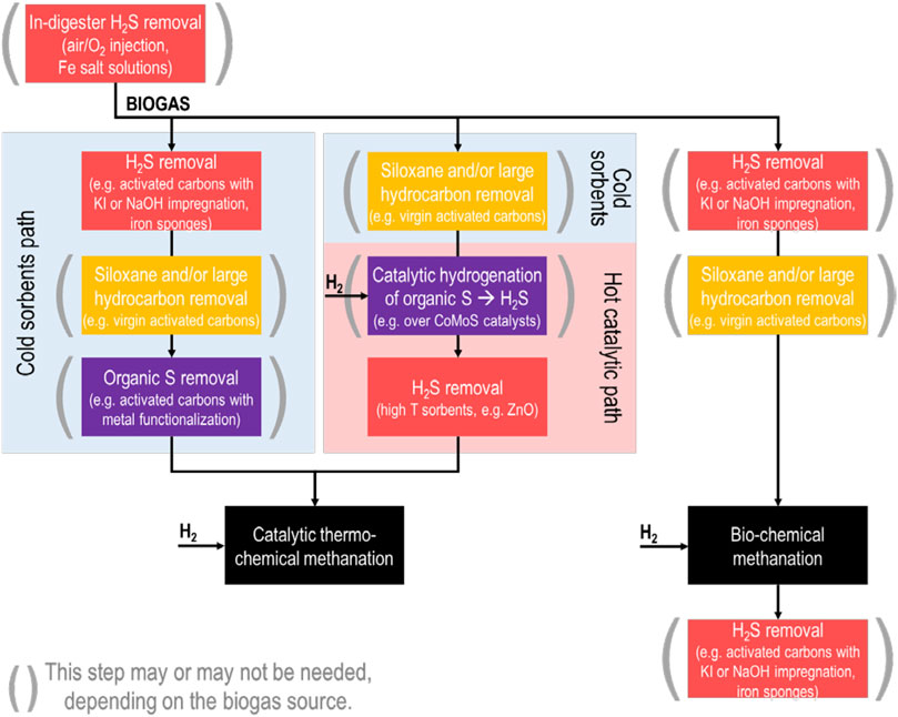
FIGURE 1. Broad overview of biogas cleaning steps which may be needed, depending on the biogas source, for Power-to-CH4 conversion of biogas. Biogas cleaning needs for bio-chemical methanation are dictated by natural gas grid purity requirements rather than the methanation process.
Even prior to individual gas cleaning process steps, it is worth mentioning that many biogas production sites already utilize in-digester desulfurization techniques. This can include injection of air or O2 (also known as “micro-aeration,” see the review of Krayzelova et al., 2015), which is used by micro-organisms in the digester to convert H2S to elemental sulfur deposits (Díaz et al., 2011). Iron-based salt solutions are also used, with the effect of precipitating iron sulfide. These techniques are effective for reducing H2S concentration in the produced biogas; however, the extent to which they may be effective to reduce other trace sulfur compounds is not fully understood. One study has found that while iron chloride successfully reduces H2S and several volatile organic sulfur compounds from biogas (Park and Novak, 2013); meanwhile, another study noted that the volatile compound dimethyl sulfide is not affected (Andersson, 2004).
Techniques for bulk H2S removal from biogas are technologically mature and well-studied, and readers are referred to the review by Abatzoglou and Boivin (2008) for a detailed overview. These would apply to any biogas pre- or post-desulfurization for biochemical methanation. In broad terms, bulk H2S removal can be achieved by adsorption onto activated carbons (unmodified/virgin or modified by chemical impregnation, with the modified carbons achieving significantly higher capacity), onto iron oxide materials, or by reaction in biological processes such as bio-trickling filters. Solvent-based solutions (for example, alkaline aqueous solutions) would not be considered advantageous for a Power-to-CH4 process, as they remove significant amounts of CO2 from the biogas in addition to H2S.
Siloxane removal from biogas has been reviewed by several authors (Ajhar et al., 2010; Soreanu et al., 2011; de Arespacochaga et al., 2015) and it is generally achieved with ambient temperature, solid sorbents. This predominantly includes activated carbons, where siloxane capacity is correlated with larger BET surface area and with larger pore volumes of pores >0.7 nm (Cabrera-Codony et al., 2014). Other sorbents such as silica gels, zeolites, and alumina have also been used.
The removal of trace sulfur compounds from biogas is not as well studied as H2S removal. Here, work done on deep desulfurization of natural gas for fuel cells is helpful. The sulfur compounds dimethyl sulfide (DMS), carbonyl sulfide (COS), and carbon disulfide (CS2) are particularly difficult to remove using ambient temperature sorbents (Dannesboe et al., 2019). Activated carbons incorporating transition metals such as iron (Fe) (de Aguiar et al., 2017) or copper (Cu) (Barelli et al., 2015) can be effective for this, as can certain zeolites if the biogas is maintained relatively dry (Calbry-Muzyka et al., 2019a).
It should be taken into account that the presence of other compounds in biogas, moisture (Calbry-Muzyka et al., 2019b) and large VOCs (Kajolinna et al., 2015) especially, can have a competitive effect with the impurities targeted by certain sorbents, causing a much earlier breakthrough of the target impurities than expected.
Apart from low-temperature sorbents, which are operationally simple but can suffer from strong competitive effects from other biogas contaminants, high-temperature catalytic/adsorption processes should also be considered for catalytic methanation. Hydro-desulfurization catalytic processes as used in the oil and gas industry can be used to convert organic sulfur compounds to H2S, after which the produced H2S can be retained by a high-temperature sorbent (such as zinc oxide, ZnO). This has been suggested as a possible solution to trace sulfur compounds in the review of Lanzini et al., (2017) on biogas cleaning for fuel cells, and it has been demonstrated in field tests for fuel cells in several past projects (He et al., 1997; Spiegel et al., 2003). In these projects, one or more cold sorbent steps are nevertheless used before the catalytic steps, for siloxane and/or VOC removal. However, there have been successful demonstrations of siloxane removal by high-temperature (400°C) alumina (Finocchio et al., 2008), indicating that it may be possible to do a full clean-up at elevated temperatures. For future biogas Power-to-CH4 projects using catalytic methanation, it would be important to demonstrate that hydro-desulfurization processes can be controlled well under variable sulfur concentrations in the biogas, in particular by testing different H2 feed rates to the hydro-desulfurization step. Alternatively, a ZnO based sorbent with promoters, operated at 400°C in presence of H2, was able to protect a methanation catalyst for 1,000 h from any deactivation (Dannesboe, 2019).
Costs
The costs of gas cleaning techniques are also a key factor for biogas Power-to-CH4 projects. Abatzoglou and Boivin estimated that biogas can be treated for bulk H2S removal for $0.03 USD/Nm3 using iron-based or activated carbon sorbents (Abatzoglou and Boivin, 2008). In a study of H2S and siloxane removal from biogas to protect a fuel cell, it was estimated that biogas cleaning would cost from 0.04–0.10 €/Nm3 of biogas where H2S removal accounted for 46–65% of capital costs and 75–95% of operating costs for a starting H2S concentration between 200 and 3,000 ppmv (de Arespacochaga et al., 2013). Similarly, a separate study of the costs of biogas cleaning for fuel cells estimated gas cleaning at $0.018 USD/kWhe (Papadias et al., 2012), corresponding to $0.06 USD/Nm3 of biogas with 60%v CH4 content. Although these are only a few studies, they can be used as an estimate of the costs of bulk H2S removal (for biochemical methanation) and of deep biogas cleaning (for catalytic methanation), especially at large scale.
Learning From Monitored Field Tests
The key difficulty with using lab-based results to inform a choice of biogas cleaning technology for any system scale-up is that real biogas—in comparison to lab-based model gas mixtures—varies strongly in trace contaminant concentration site-to-site and day-to-day. This means that field-based demonstrations, where biogas comes from a real biogas source, are essential to understanding and validating gas cleaning processes.
The ability to monitor and quantify key compounds, ideally online, is not straightforward at these low concentrations. Often, gas sampling is performed on-site for off-site analysis of trace compounds, which carries the risk of analyte loss, with no single sampling vessel type (bags, containers, adsorption tubes) having been found to be appropriate for all biogas contaminants (Arrhenius et al., 2017). This necessarily leads to a piecemeal approach, where only a subset of compounds is measured, often non-continuously.
Then, many field tests are performed to demonstrate a technology which comes downstream of any gas cleaning process, which means that the gas cleaning step is intentionally oversized with large safety factors to ensure that the downstream unit is not harmed. However, this then makes it difficult to accurately represent the capacity of sorbent-based gas cleaning systems, where the accumulative nature of the process means that the capacity will not be known until a breakthrough has occurred.
Testing of biogas cleaning units until full breakthrough can bring significant insight into the performance and failings of the system under real conditions. From field tests in biogas, it has been shown that iron-based sorbents are able to remove H2S at efficiencies >98% despite inlet concentrations varying from 104 to 1,852 ppmv (de Arespacochaga et al., 2013), that high levels of moisture can reduce a promising zeolite-based sorbent’s trace sulfur capacity to nearly zero (Calbry-Muzyka et al., 2019a), that non-H2S sulfur compounds such as carbonyl sulfide (COS), carbon disulfide (CS2), and dimethyl sulfide break through desulfurization steps much earlier than H2S (Calbry-Muzyka et al., 2019a; Dannesboe et al., 2019), and that siloxanes (especially the light siloxanes L2-L4) can be measured to break through activated carbon beds much earlier than expected from single-contaminant lab tests due to the competitive presence of other volatile organic compounds in real biogas (Arnold and T. Kajolinna, 2010).
The coupling of competitive adsorption between the many dozens of biogas trace compounds and of the concentration fluctuations of specific compounds can be understood, along with their effect on adsorptive biogas cleaning techniques, by the example in Figure 2. Here, a two-stage biogas cleaning process is used: 1) bulk H2S removal using a commercial sorbent based on copper oxide (CuO); 2) trace sulfur removal using a commercial sorbent based on a ceramic-activated-carbon composite. The biogas, which originated from agricultural, food, and green wastes, contained no detectable siloxanes. H2S was monitored online using a portable gas chromatograph (GC) with thermal conductivity detector (TCD) (microGC-TCD, see method details in Calbry-Muzyka et al., 2019a). The remaining sulfur compounds were monitored online as total sulfur using a sulfur chemiluminescence detector (SCD) (Calbry-Muzyka et al., 2019b). This field test was performed to evaluate the gas cleaning alone; no methanation reactor was used downstream. This allowed a full study of the breakthrough behavior.
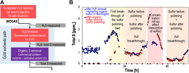
FIGURE 2. Example of the use of a field test to evaluate the capacity of sorbents for trace sulfur compounds in biogas. The biogas was produced from agricultural waste and food/green waste and contained undetectable levels of siloxanes. (A) Shows a schematic representation of the biogas treatment steps, and (B) shows the resulting total sulfur measurements after different stages of biogas treatment.
Although no H2S breakthrough was ever detected in this test, management of trace organic sulfur compounds was much more difficult. Even though the sorbent for trace sulfur removal had been chosen based its good desulfurization performance in lab studies using variable gas humidity and variable concentrations of VOCs in the feed gas, its performance in the field was significantly impeded. The breakthrough plot in Figure 2 shows a clear concentration roll-up effect, where the concentration at the bed outlet exceeds that at the bed inlet. This indicates a competitive adsorption effect, for example from much higher concentrations of VOCs than had been expected in the gas. As result, practically all organic sulfur adsorbed in the first 20 h is desorbed between 36 and 48 h of test duration. Events such as these must be avoided when scaling up methanation technology. For this reason, field testing of biogas cleaning steps with monitoring and with a bypass of downstream catalytic reactors must be done to demonstrate robustness to real biogas.
Synthesis and Upgrading of Biomethane
The production of biomethane downstream of the gas cleaning consists of at least two steps: the main conversion and the gas upgrading leading to injectable gas. A prerequisite for these two processes is the supply of cleaned biogas and of hydrogen; further, a good integration of all processes is needed to improve plant performance and to minimize costs.
As discussed in the last section, the quality of biogas is changing over time; moreover, also the biogas production itself shows (e.g., seasonal) fluctuations depending on the plant and the feedstock availability. On the other hand, renewable electricity production as well as the electricity price strongly depend on varying and sometimes even stochastic phenomena such as the weather and the interplay between supply and demand. This results in the desire to, at least partly, adapt the hydrogen production by water electrolysis according to the electricity prices. This explains why many Power-to-Gas projects apply PEM-electrolysis that specifically was developed for fast load changes. The biogas production however follows other time patterns.
In the short term, the discrepancy can be solved by a hydrogen tank at intermediate pressures close to the pressure of the electrolysis (30–50 bar) to avoid additional compression (Gorre et al., 2020). The tank allows decoupling of the hydrogen production and its consumption for several days. A methanation technology comprising deep part load and at least moderately fast load changes allows for smaller hydrogen tanks or for longer transitory periods. Some biogas plants also have intermediate gas storages that allow them to store the produced gas for a few hours.
To overcome longer periods of unavailability or high costs of hydrogen, an even more flexible plant integration is needed. A recent study showed that the same membrane system can be used for two modes of operation of a biogas Power-to-Gas plant: as upgrading for the product enabling H2 recycle in case of direct methanation of biogas in times when cheap renewable electricity and H2 are available, or as classical biogas separation system in other times. This allows to avoid the necessity to buy expensive H2 in times when renewable electricity is scarce and the hydrogen tank is not sufficient to close the gap. Moreover, such a system also represents a back-up solution for uninterrupted biomethane production in times of maintenance or operation stop of electrolysis or methanation (Gantenbein et al., 2020).
Another important aspect of plant integration is the use of heat flows. Both electrolysis and methanation are exothermic; the optimal use of these heat flows depends however on the available temperature level. Alkaline and PEM electrolysis as well as biological methanation operate at moderate temperatures of 30–65°C which limits the heat use to (pre-)warming of digesters etc. Higher temperature heat demand, e.g., for des-infective treatment of feedstock or to reach the required temperature level in digesters or for regeneration in sorption based gas up-grading plants, can be supplied by catalytic methanation operating at >300°C (see next section). Alternatively, the high temperature heat of methanation reactors can also be used to raise steam for solid oxide electrolysis, which allows for a significantly higher efficiency of the electrolysis step and therefore of the overall process (Dannesboe, 2019).
Methanation
The reaction of CO2 with H2, detected by Sabatier and Senederens in 1902, is strongly exothermic and limited by thermodynamic equilibrium:
This implies that the heat of reaction has to be removed to allow for high conversion. The presence of CH4 from the raw biogas dampens the temperature increase compared to reactors fed with pure CO2 and H2; however, hot spots of up to 680°C can easily be reached in adiabatic reactors.
Furthermore, the methanation reaction needs to be catalyzed, by either suitable microorganisms or chemical catalysts such as nickel, ruthenium, iron etc. This necessitates appropriate contact between the reacting gases and the solid catalysts or the microorganisms living in water phase. Because of these two challenges (heat and mass transfer), a number of different reactor concepts have been developed (Götz et al., 2016; Rönsch et al., 2016; Schildhauer, 2016), see Figure 3.
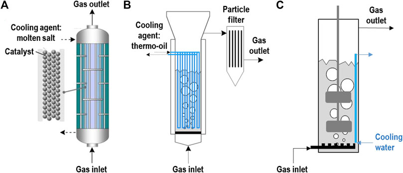
FIGURE 3. Important methanation reactor concepts: (A) Cooled fixed bed (left), (B) Catalytic bubbling fluidized bed (middle), (C) Stirred bubble column for biological methanation (right).
Biological Methanation
When microorganisms are used as catalysts, the reactor contains a water phase, which serves both as the habitat for the microorganisms and as the solvent for the nutrients necessary for the growth of the microorganisms, such as Na2S and NH3. The microorganisms metabolize the CO2 and the H2; CH4 is then a waste by-product. The water produced in the methanation reaction adds to the volume of the water phase, i.e., the excess has to be separated while not losing too much of the (expensive) nutrients. Nutrient recovery is therefore an important research topic (Hafenbradl, 2020). The heat of reaction is produced at the temperature level that is suitable for the microorganisms (35–70°C). To avoid overheating of the reactor, the water phase easily can be cooled either internally by immersed cooling coils or in an external heat exchanger fed with cooling water, which limits the further use of this heat flow. On the other hand, biological methanation reactors have to be protected from freezing during winter.
The big challenge for biological methanation is to provide sufficient contact between the gas phase and the water phase. CO2 dissolves to some extent in water; H2 however only very weakly. Therefore, the reactor systems developed so far try to maximize gas-liquid interface area by applying stirred bubble columns. These induce additional energy consumption of 2–2.5% of the electricity used in the electrolysis, leading to an efficiency loss of the same order of magnitude (Heller, 2016; Hafenbradl, 2020).
As an alternative, counter-current trickling bed reactors are under development (Rachbauer et al., 2016) that allow large gas-liquid interfaces without stirring. Instead, the pump for the recirculation of the liquid has to be operated.
Catalytic Methanation
While biological methanation was investigated to some extent already in the 1970s and reconsidered a few years ago, catalytic methanation has been continuously used since decades and further developed. Methanation of small traces of carbon oxides in the H2 flow to ammonia synthesis reactors is state of the art; further catalytic methanation for the production of synthetic natural gas (SNG) from coal gasification gas has been scaled-up to the GW-scale and is still in operation in the US and especially in China (Schildhauer, 2016). Decentralized methanation of biomass-based gas streams has been under development since nearly 20 years, especially for the conversion of wood gasification based gas (Rabou and Bos, 2012; Held, 2016; Rabou et al., 2016; Schildhauer, 2016; Schildhauer and Biollaz, 2016; Thunman et al., 2018). Since about 10 years, the methanation of CO2 and biogas for Power-to-Gas applications has been considered (Specht et al., 2016).
Catalytic methanation proceeds at temperatures above 200–300°C on supported metal catalysts, where an active metal, for example nickel or ruthenium, is distributed over the large (inner) surface of porous ceramic support materials such as alumina and silica. Well performing commercial catalyst exist since more than 50 years; a recent article reviews the progress in synthesis of suited catalysts for CO2 methanation (Lv et al., 2020). The challenge in catalytic methanation reactors is to remove the significant heat of reaction from the reactor to avoid catalyst sintering and conversion limitation due to the thermodynamic equilibrium. The high temperature level allows the recovery of two heat flows at favourable temperature levels: the heat of reaction (above 250–300°C) and the heat of condensation of the produced water (depending on the pressure level, but usually above 150°C), see (Witte et al., 2018a).
For the classical reactor system, the adiabatic fixed bed reactor, a temperature increase to a certain level (550°C or 700°C depending on the applied catalyst) is considered acceptable, and is controlled by the recirculation of cooled product gas. As the temperature increase impedes full conversion, one further reactor and at least one third reactor after condensation is necessary.
In the last 2 decades, cooled fixed bed reactors have been developed (e.g., Hashimoto et al., 1999; Specht et al., 2016) that allow the removal of the heat of reaction in the reactor and to realize a temperature profile that favors high conversion, also by different cooling zones (Specht et al., 2016; Moioli et al., 2019). To avoid high pressure drop, catalyst particles in the range of a few millimetres diameter are usually used. As the radial heat transfer in reactors filled with coarse catalyst particles is limited, several fixed bed reactor concepts with high internal heat transport by thermal conduction have been developed. The necessary large amount of conducting metal is implemented in the reactors either as wrapped metal monoliths or by metal plates which form channels in the sub millimetre range (LeViness et al., 2014; Dittmeyer et al., 2017; Bengaouer et al., 2018; Neuberg et al., 2019; Chwoła et al., 2020) that are coated with catalyst or filled with catalyst powder. Further, metal foams (Frey et al., 2016; Bengaouer et al., 2018) and static mixer type packings (Schildhauer et al., 2009; Sudiro et al., 2010) and recently also 3D printed metal structures are discussed (Danaci et al., 2018).
A completely different approach is followed by reactor systems that allow the movement of the catalyst by fluidization, either in the up-flowing gas stream (bubbling gas-solid fluidized beds, Friedrichs et al., 1985, Schildhauer and Biollaz, 2016) or in an inert liquid with fine, suspended catalyst powder (three-phase gas-liquid-solid bubble columns, Frank et al., 1976; Lefebvre et al., 2015). The advantage of the fluidization is dual: 1) due to the movement of the catalyst particles, the heat production is spread over the complete volume of the reactor where it can be removed by immersed heat exchangers; 2) due to the movement, the local heat transfer rate to the immersed surface is increased. As a result, both reactor types operate close to isothermal conditions and allow for relatively fast load changes (in the range from 30 to 100%, Friedrichs et al., 1985) without significantly changing temperature profiles and thus without the connected thermal stress to the catalyst. The challenges in the bubble column reactor is the low gas-liquid mass transfer (similar as in most biological reactors). For the bubbling gas-solid fluidized bed reactor, a sufficiently stable catalyst has to be applied to avoid loss of catalyst material due to attrition.
Upgrading
The regulations for unlimited injection of biomethane into the gas grid differ over Europe. While in the North-West of Germany and in the Netherlands, natural gas from the Groningen field with a relatively low CH4 content dominates, in most part of Europe, CH4 contents for injected gas of >96% are mandatory. A further differentiation is caused by the limitations with respect to residual H2 content, which is 5% in Spain, 2% in Germany and Switzerland and even below 0.5% in Italy.
Most reactor concepts do not or not easily allow for full conversion with low residual H2 contents, either due to mass transfer limitation (biological stirred tank reactors or catalytic gas-liquid-solid bubble columns) or to thermodynamic equilibrium at the temperatures necessary for sufficient catalytic activity (all catalytic reactors). In case of mass transfer limitations, lower gas throughput helps, but leads to larger reactor volumes (Hafenbradl, 2020). For catalytic reactors, the necessary gas quality can be achieved by either a reactor zone with low temperature and an (expensive) low temperature-active noble metal catalyst (Moioli et al., 2019), or by condensation to remove water and a second reactor (Specht et al., 2016; Witte et al., 2018a; Dannesboe, 2019; Guilera et al., 2019) which however necessitates a further heat exchanger system.
An alternative that can be used for any reactor system is the use of a membrane that separates unreacted H2 and CO2 from the CH4. For this, commercial biogas-upgrading membranes can be used. In state of art polymeric membranes, most of the product CH4 stays on the high pressure side of the membrane (retentate). Humidity and a fraction of the CH4 permeate together with H2 and CO2 to the low-pressure side of the membrane and have to be recycled to the reactor to avoid loss of valuable H2 and CH4.
Due to the low residual amounts of H2 and CO2 after well-performing catalytic reactors (below 10 and 2%, respectively (Specht et al., 2016; Witte et al., 2019), the permeate can consist of CH4 up to more than 60%. This raises the question of cost optimization as the CH4 recompression is connected to operational costs and higher capital costs that add to the membrane costs. Witte et al. (2018b) compared the costs of a co-current membrane system to the costs of a second catalytic reactor and did not find a significant difference based on the available cost information from literature. A recent experimental study showed however that counter-current membrane operation allows for smaller membrane areas and/or lower pressure gradients which opens room for further optimization (Gantenbein et al., 2020).
Successful Long Duration Tests
In the last years, a number of long duration tests (mostly at a Technology Readiness Level of 5) were conducted in Germany (Heller, 2016; Specht et al., 2016), Denmark (Dannesboe, 2019; Hafenbradl, 2020), Spain (Guilera et al., 2019), Austria (Rachbauer et al., 2016) and Switzerland (Witte et al., 2019) to demonstrate the technical feasibility of direct methanation of real biogas. These tests cover several reactor concepts (catalytic: cooled fixed bed (Specht et al., 2016), fluidized bed (Witte et al., 2019), micro-structured heat exchange reactor (Guilera et al., 2019); biological: stirred bubble columns, trickle bed (Heller, 2016; Rachbauer et al., 2016; Hafenbradl, 2020) and biogas sources. Table 1 gives an overview of the tests for which detailed public information is available.
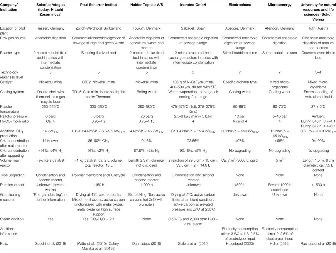
TABLE 1. Overview long duration testing of direct biogas methanation.
The volume of the main reactor ranges from around few liters (catalytic) to several cubic meters (biological), while the produced CH4 ranges from 6.6 to 550 kWHHV (Hafenbradl, 2020). Due to the limited information available, a clear order of methanation capacity per reactor volume is not possible, but the catalytic reactors outperform the biological ones by about one order of magnitude.
Nickel-based catalysts dominate in catalytic reactors, while both specialized archaea and mixed cultures are used in biological plants. The operation conditions with respect to H2 to CO2 molar ratio (around the stoichiometric value of 4) and pressure (5–10 bar) are quite similar in all reactors; only the fixed bed reactor concept by Haldor Topsøe A/S operates at 20 bar (Dannesboe, 2019).
The temperature range is very specific for each reactor type where the difference of the reactor concepts leads to diverse temperature range situation. The biological reactors operate at the temperature range suitable for meso- and thermophilic microorganisms at 35–65°C leading to the above mentioned limitations of using this heat. The catalytic reactors with very high internal heat transport properties (microchannel reactor, Guilera et al., 2019) show relatively flat temperature profiles with maximum 100 K gradient, while the fixed bed reactors are characterized by a hot spot above 550°C at the reactor inlet (Specht et al., 2016). The fluidized bed proved to be nearly isothermal around 350°C (Witte et al., 2019).
Unfortunately, not all projects explain their gas cleaning in detail, but the well-described ones are quite different due to the varying biogas sources. In the test in Zurich, Switzerland, mixed gas from sewage sludge digestion (80%) and green waste digestion (20%) was converted, which has a moderate level of terpenes and siloxanes, but a significant amount of organic sulfur species (Witte et al., 2019). Here, a combination of cold adsorbers with metal oxides and impregnated activated carbon reached the goal to keep sulfur concentrations in the feed to the catalytic methanation significantly below 1 ppmv (Calbry-Muzyka et al., 2019a). In Foulum/Denmark, biogas from digestion of agricultural waste and manure was used (Dannesboe, 2019). The gas cleaning concept consists of a bio-trickling filter with oxygen addition, active carbon at ambient temperatures and a promoted ZnO bed at elevated temperatures. The plant in Spain applied activated carbons at two pressure levels and a hot ZnO bed (Guilera et al., 2019).
All of the reactors were operated for several hundreds to more than 1,000 h and reached the necessary gas quality for the injection into the local gas grid, for which the conditions differ significantly within Europe. Most catalytic process concepts include an upgrading step, either a second reactor after intermediate condensation or a membrane to recycle unreacted gas, especially H2. Biological reactors can reach the necessary gas quality in one step due to the favourable thermodynamics at low temperatures, when the throughput is not too high, i.e., the reactor is sufficiently large.
Discussion
This overview of different process concepts for direct methanation of biogas shows very different answers to the three main challenges in this process chain: management of impurities in the raw biogas, heat removal in the main reactor (where the exothermic reaction takes place), and up-scaling options and market implementation.
Gas Cleaning
The impurities in the biogas strongly depend on the feedstock and the chosen operation conditions. While siloxanes are the challenge in the otherwise relatively clean gas from anaerobic sewage sludge digestion, green waste digestion increases the amount of aromatics and terpenes. Although terpenes themselves are not necessarily a problem in the catalytic methanation reactors, they can impede the removal of sulfur species in adsorption beds. With respect to sulfur species, it is reasonable to expect, besides significant amounts of H2S, up to a few ppmv of carbonyl sulfide and organic sulfur species (mercaptans and thioethers). The latter is no problem in biological methanation, but is detrimental to catalyst stability in catalytic methanation. Therefore, thorough non-H2S sulfur removal to the sub-ppm level is absolutely necessary. To avoid high specific costs, the processes developed for small-scale biogas methanation do not utilize the gas cleaning steps as found at large scale in refineries and coal gasification plants, but rather use gas drying at low temperatures combined with several sorbents based on activated carbon and metal oxides, partly at elevated temperatures.
Due to the varying composition of the biogas, no standard gas cleaning solution seems to have been developed so far. Further development in this field and cost optimization will be necessary, accompanied by developing standard methods for analytics. The latter is needed both for determining the biogas composition to control the H2/CO2 molar ratio, and for impurity measurement. Finally, it was shown that long duration tests of the chosen gas cleaning measures with the real gas (and thus with the varying concentrations of impurities) are of utmost importance to verify the gas cleaning performance.
Concepts for Methane Synthesis and Upgrading
The challenge of removing heat from the methanation reactor has led to a relatively large number of reactor concepts, of which several have been tested at TRL 5 or greater for direct methanation of real biogas. Reactors with liquid hold-up or moving catalyst particles, i.e., the biological and the fluidized bed reactors, allow for nearly isothermal operation. Reactors with fixed catalyst beds experience significant temperature gradients and hot spots, which might lead to catalyst damage and necessitates measures such as recirculation cooling. Strong temperature gradients can be a problem when changing the gas load, as then the temperature profile moves within the reactor. In such cases, too fast local temperature changes have to be avoided in order not to compromise the catalyst stability. While solutions for fast load changes (within few minutes) are discussed in the scientific literature (Bremer et al., 2017; Kreitz et al., 2019; Theurich et al., 2019), in reality a tank for H2 storage can significantly dampen this necessity. To limit the size of this H2 tank, however, relatively low part load or even simple stop and restart of the methanation reactor operation are helpful. Here, biological methanation reactors have shown an impressive ability to interrupt for hours the H2 feed without any problem (Hafenbradl, 2020).
All process concepts discussed here allowed the attainment of the gas quality (minimum CH4 content, maximum H2 content) necessary for the injection into the respective local grid, which is easier to achieve in areas such as the north-west of Germany and in Spain (<5% H2) than in areas such as Switzerland or the south of Germany (<2% H2). Biological methanation reactors at moderate throughput reach this gas quality due to low operating temperatures and the inherent, favourable thermodynamics, without further upgrading (besides the drying and odoration steps that are mandatory for all processes). Catalytic reactors need an intermediate condensation step and a second reactor or a membrane for recirculation of unreacted gas; in other words, compared to biological methanation, more units are needed. On the other hand, the higher temperature level in catalytic reactors enable the further use of the heat of reaction and the heat of water condensation, which improves the potential synergies with the biogas plant, the overall efficiency and therefore the process economics.
Costs
Generally, Power-to-Gas plant costs are dominated by the electricity costs and the capital costs of the electrolyser (Witte et al., 2018b). The costs of electrolysers are expected to decrease markedly in future: studies estimate the average costs of alkaline electrolysers at 1,300 €/kWel in 2017 dropping to <500 €/kWel by 2050, of PEM electrolysers at 1,900 €/kWel in 2017 dropping to 500 €/kWel in 2050, and of high-temperature electrolysers at 3,570 €/kWel in 2017 dropping to 535 €/kWel in 2050 (Thema et al., 2019). Costs of biogas cleaning to a level acceptable for methanation have been estimated in the range of 0.03–0.10 €/Nm3 of biogas, as discussed earlier in section “Costs”.
In the methanation step itself, capital costs for the reactor, the compressor and heat exchangers have the most significant impact as well as the electricity costs for stirrers and compressors. Different from electrolysers, the specific costs of these units are strongly depending on the plant size with a tendency that they decrease by a factor of more than two for a ten times larger plant. It therefore does not make sense to indicate absolute numbers for the general discussion, while it is possible to consider the differences between the respective technologies.
To withstand the temperatures or the corrosive potential of CO2 dissolved in water, all methanation reactors require a stainless steel system at elevated pressure (at least PN 16), therefore the number and size of the reactor(s) and heat exchangers has direct importance for the costs. Here catalytic reactors with limited heat transfer (fixed beds) and biological reactors are at a disadvantage in comparison with, for example, fluidized beds. Compressor costs can be minimized by lower pressure drop through the reactor, and by lower recirculation rates, for instance by improved heat transfer in externally cooled fixed bed reactors, or due to more selective membranes in case of membrane based upgrading. Stirrer costs in biological reactors can be optimized by well-designed gas injection systems; due to the disadvantageous scaling rules for the energy consumption of stirred tank reactors, the stirring requirements might however limit the feasible diameter of this reactor type. Furthermore, the direct methanation of biogas itself has already an energy advantage over state-of-the art biogas Power-to-Gas plants, as these first separate the CO2 from CH4 before feeding to the methanation unit, which represents a continuous energy loss.
So far, a consistent, detailed cost comparison for the overall process (total cost of ownership) for biological and catalytic methanation is missing; only the cost differences between catalytic fixed bed and fluidized bed processes have been investigated (Witte et al., 2018b), showing a slight advantage for fluidized bed reactors over cooled fixed beds. From this comparison and the aspects above, it can be expected that the real cost differences will only be known once demonstration plants of each technology have been built and operated for several years.
Upscaling and Market Implementation
To reach the demonstration phase (TRL 8), most technologies have to undergo upscaling. While stirred bubble columns for biological methanation have been built up to 350 kWHHV,CH4 (TRL 7), biological trickle bed reactors have not yet reached the pilot scale (TRL 6,7). In Dietikon, Switzerland, planning and initial construction work is ongoing for a stirred biological reactor from microbenergy that will convert the H2 from a 2.5 MWel electrolyser. At this site, there exists not only a waste water treatment plant delivering the biogas, but also a source of renewable electricity which can be used without paying a grid use fee.
Several catalytic systems have been extensively tested for methanation of pure CO2 or producer gas from wood gasification: Adiabatic fixed bed reactors at 20 MWHHV,CH4 in the GoBiGas plant (Held, 2016); cooled fixed bed reactors at 3 MWHHV,CH4 in Werlte/Germany (Specht et al., 2016); catalytic fluidized bed reactors at 1 MWHHV,CH4 in Güssing/Austria (EU-project BioSNG, Schildhauer and Biollaz, 2016); catalytically coated monoliths at >500 kWHHV,CH4 and micro-structured heat exchanger reactors at up to 90 kWHHV,CH4 within the EU project Store and Go Roadmap (2019). Based on this experience, it will be possible (but has not yet been realized) to test these reactor types in pilot scale with biogas and to demonstrate their options for flexible load gradients and low part load. Additionally, the interaction of methanation reactors with upgrading membranes needs further investigation. Therefore, an important gap on the way to market implementation is the erection and operation of demonstration plants, which under the current market situation (high price for renewable electricity including grid use fees, too low value of renewable gas) needs support measures.
Outlook
When comparing different Power-to-Methane process concepts, the direct methanation of biogas is closest to economic feasibility as it combines the conversion of (relatively expensive) renewable H2 with the upgrading of (relatively cheaper raw biogas) to valuable biomethane. This is an important advantage over schemes that work with CO2 which must first be separated from biogas, air or flue gas (Biollaz et al., 2017). With respect to life cycle green house gas emission, direct methanation outperforms the methanation of CO2 separated from biogas (Zhang et al., 2020) due to the avoided effort. This is especially significant, if a pressure swing adsorption was used for the CO2 separation because of its relatively high methane emissions. Still, due to the absence of noble metal catalyst or similarly rare materials in the methanation and gas cleaning, the life cycle greenhouse gas emission are completely dominated by the electrolysis and to the largest extent by the CO2 intensity of the used electricity.
While most biogas plants are relatively small with scales of 1 to few MW, there is generally a large number of waste water treatment plants that are close to the natural gas grid. In addition, the number of biogas plants with green and agricultural waste and manure is increasing. At the same time, the subsidies for electricity production from biogas are decreasing in many countries, which further enlarges the potential market for direct methanation of biogas.
To exploit this market potential, on the technical side the most important steps are gaining a better understanding and cost optimization of the gas cleaning as well as demonstration plants for the different methanation and upgrading technologies. In the coming years, the specifications with respect to residual H2 in biomethane injected into the natural gas network might move to higher values, which would facilitate the operation of biogas production and decrease the upgrading effort. On the economic side, besides more consistent comparison of technologies at demo-scale operation, the potential synergies within the biogas sites should be the focus: the use of heat flows from the methanation plant for the biomass handling, efficient high-temperature electrolysis or neighbored plants; furthermore, synergies with respect to services and trained staff; and finally flexibility options with respect to time of electricity consumption.
Author Contributions
All authors agree to be accountable for the content of the work. AC-M focused on the gas cleaning part, TS on the methanation/upgrading part and the discussion.
Funding
Our research was financially supported by the Swiss Innovation Agency lnnosuisse and is part of the Swiss Competence Center for Energy Research SCCER BIOSWEET. The authors would like to acknowledge financial and other support from the Swiss Federal Office for Energy (SFOE), FOGA and the ESI Platform at PSI.
Conflict of Interest
The authors declare that the research was conducted in the absence of any commercial or financial relationships that could be construed as a potential conflict of interest.
Acknowledgments
The authors would like to thank all colleagues of the Thermochemical Processes group at PSI as well as their industrial collaborators for valuable discussions.
Abbreviations
GC, gas chromatograph; ppbv/ppmv, parts per billion/million on a volume basis, which for an ideal gas mixture is equivalent to a molar basis; SCD, sulfur chemiluminescence detector; SNG, synthetic natural gas; TCD, thermal conductivity detector; TRL, technology readiness level; VOC, volatile organic compound.
References
Abatzoglou, N., and Boivin, S. (2008). A review of biogas purification processes. Biofuels Bioprod. Biorefin. 3 (1), 42–71. doi:10.1002/bbb.117
Ajhar, M., Travesset, M., Yüce, S., and Melin, T. (2010). Siloxane removal from landfill and digester gas—a technology overview. Bioresour. Technol. 101 9, 2913–2923. doi:10.1016/j.biortech.2009.12.018
Andersson, F. A., Karlsson, A., Svensson, B. H., and Ejlertsson, J. (2004). Occurrence and abatement of volatile sulfur compounds during biogas production. J. Air Waste Manag. Assoc. 54 (7), 855–861. doi:10.1080/10473289.2004.10470953
Arnold, M., and Kajolinna, T. (2010). Development of on-line measurement techniques for siloxanes and other trace compounds in biogas. Waste Manag. 30 (6), 1011–1017. doi:10.1016/j.wasman.2009.11.030
Arrhenius, K., Yaghooby, H., Rosell, L., Büker, O., Culleton, L., Bartlett, S., et al. . (2017). Suitability of vessels and adsorbents for the short-term storage of biogas/biomethane for the determination of impurities—siloxanes, sulfur compounds, halogenated hydrocarbons. BTEX. Biomass and Bioenergy 105, 127–135. doi:10.1016/j.biombioe.2017.06.025
Bach, C., Beuse, M., Georges, G., Held, M., Heselhaus, S., Korba, P., et al. . (2019). Perspectives of Power-to-X technologies in Switzerland: a white paper. Editors T. Kober, and C. Bauer, 2nd Edn. Villigen, Switzerland: Paul Scherrer Institute. doi:10.3929/ethz-b-000352294
Bailera, M., Lisbona, P., Romeo, L. M., and Espatolero, S. (2017). Power to Gas projects review: lab, pilot and demo plants for storing renewable energy and CO2. Renew. Sustain. Energy Rev. 69, 292–312. doi:10.1016/j.rser.2016.11.130
Barelli, L., Bidini, G., Desideri, U., Discepoli, G., and Sisani, E. (2015). Dimethyl sulfide adsorption from natural gas for solid oxide fuel cell applications. Fuel Process. Technol. 140, 21–31. doi:10.1016/j.fuproc.2015.08.012
Bengaouer, A., Ducamp, J., Champon, I., and Try, R. (2018). Performance evaluation of fixed-bed, millistructured, and metallic foam reactor channels for CO2 methanation. Canad. J. Chem. Eng. 96, 1937–1945. doi:10.1002/cjce.2314
Biollaz, S., Calbry-Muzyka, A., Schildhauer, T. J., Witte, J., and Kunz, A. (2017). Final Report BfE-Projekt SI/501284-04. Direct methanation of biogas. Available at: https://www.aramis.admin.ch/Texte/?ProjectID=36924 (Accessed June 1, 2020).
Biswas, S., Kulkarni, A. P., Giddey, S., and Bhattacharya, S. (2020). A review on synthesis of methane as a pathway for renewable energy storage with a focus on solid oxide electrolytic cell-based processes. Front. Energy Res. 8, 570112. doi:10.3389/fenrg.2020.570112
Bremer, J., Rätze, K. H. G., and Sundmacher, K. (2017). CO2 methanation: optimal start‐up control of a fixed‐bed reactor for power‐to‐gas applications. AIChE J. 63, 23–31. doi:10.1002/aic.15496
Buttler, A., and Spliethoff, H. (2018). Current status of water electrolysis for energy storage, grid balancing and sector coupling via power-to-gas and power-to-liquids: a review. Renew. Sustain. Energy Rev. 83 (3), 2440–2454. doi:10.1016/j.rser.2017.09.003
Cabrera-Codony, A., Montes-Morán, M. A., Sánchez-Polo, M., Martín, M. J., and Gonzalez-Olmos, R. (2014). Biogas upgrading: optimal activated carbon properties for siloxane removal. Environ. Sci. Technol. 48 (12), 7187–7195. doi:10.1021/es501274a
Calbry-Muzyka, A. S., Gantenbein, A., Schneebeli, J., Frei, A., Knorpp, A. J., Schildhauer, T. J., et al. . (2019a). Deep removal of sulfur and trace organic compounds from biogas to protect a catalytic methanation reactor. Chem. Eng. J. 360, 577–590. doi:10.1016/j.cej.2018.12.012
Calbry-Muzyka, A. S., Indlekofer, J., Schneebeli, J., and Biollaz, S. M. A. (2019b). Online measurement of sub-ppmv total sulfur in biogas by chemiluminescence. Energy Fuel. 33 (10), 9859–9869. doi:10.1021/acs.energyfuels.9b01778
Chwoła, T., Spietz, T., Więcław-Solny, L., Tatarczuk, A., Krótki, A., Dobras, S., et al. . (2020). Pilot plant initial results for the methanation process using CO2 from amine scrubbing at the Łaziska power plant in Poland. Fuel 263, 116804. doi:10.1016/j.fuel.2019.116804
Danaci, S., Protasova, L., Snijkers, F., Bouwen, W., Bengaouer, A., and Marty, P. (2018). Innovative 3D-manufacture of structured copper supports post-coated with catalytic material for CO2 methanation. Chem. Eng. Process. 127, 168–177. doi:10.1016/j.cep.2018.03.023
Dannesboe, C. (2019). Catalytic upgrading of CO2 in biogas. PhD thesis. Aarhus (Denmark): University of Aarhus.
Dannesboe, C., Hansen, J. B., and Johannsen, I. (2019). Removal of sulfur contaminants from biogas to enable direct catalytic methanation. Biomass Conv. Bioref. doi:10.1007/s13399-019-00570-7
de Aguiar, M. F., and Coelho, G. L. V. (2017). Adsorption of sulfur compounds from natural gas by different adsorbents and desorption using supercritical CO2. J. Environ. Chem. Eng. 5 (5), 4353–4364. doi:10.1016/j.jece.2017.07.079
de Arespacochaga, N., Valderrama, C., Mesa, C., Bouchy, L., and Cortina, J. L. (2013). Biogas deep clean-up based on adsorption technologies for Solid Oxide Fuel Cell applications. Chem. Eng. J. 255, 593–603. doi:10.1016/j.cej.2014.06.072
de Arespacochaga, N., Valderrama, C., Raich-Montiu, J., Crest, M., Mehta, S., and Cortina, J. L. (2015). Understanding the effects of the origin, occurrence, monitoring, control, fate and removal of siloxanes on the energetic valorization of sewage biogas—a review. Renew. Sustain. Energy Rev. 52, 366–381. doi:10.1016/j.rser.2015.07.106
Díaz, I., Pérez, S. I., Ferrero, E. M., and Fdz-Polanco, M. (2011). Effect of oxygen dosing point and mixing on the microaerobic removal of hydrogen sulphide in sludge digesters. Bioresour. Technol. 102 (4), 3768–3775. doi:10.1016/j.biortech.2010.12.016
Dittmeyer, R., Boeltken, T., Piermartini, P., Selinsek, M., Loewert, M., Dallmann, F., et al. . (2017). Micro and micro membrane reactors for advanced applications in chemical energy conversion. Current Opinion in Chemical Engineering 17, 108–125. doi:10.1016/j.coche.2017.08.001
Dumas, C., Ottosen, L. D. M., Escudié, R., and Jensen, P. (2020). Biological methanation or (Bio/Syn)-gas upgrading. Front. Energy Res. 8, 30. doi:10.3389/fenrg.2020.00030
Erekson, E. J., and Bartholomew, C. H. (1983). Sulfur poisoning of nickel methanation catalysts: II. effects of H2S concentration, CO and H2O partial pressures and temperature on deactivation rates. Appl. Catal. 5 (3), 323–336.
European Organization for Standardization (2016). EN 16723-1—natural gas and biomethane for use in transport and biomethane for injection in the natural gas network—part 1: specifications for biomethane for injection in the natural gas network. Brussels, Belgium: European Organization for Standardization.
European Organization for Standardization (2017). EN 16723-2—natural gas and biomethane for use in transport and biomethane for injection in the natural gas network—part 2: automotive fuels specifications. Brussels, Belgium: European Organization for Standardization.
Finocchio, E., Garuti, G., Baldi, M., and Busca, G. (2008). Decomposition of hexamethylcyclotrisiloxane over solid oxides. Chemosphere 72 (11), 1659–1663. doi:10.1016/j.chemosphere.2008.05.032
Frank, M. E., Sherwin, M. B., Blum, D. B., and Mednick, R. L. (1976). “Liquid phase methanation—shift PDU results and pilot plant status,” in Proceeding of eighth synthetic pipeline gas symposium, Chicago, IL, October 1976 (Chigago, IL: American Gas Association), 159–179.
Frey, M., Romero, T., Roger, A.-C., and Edouard, D. (2016). Open cell foam catalysts for CO2 methanation: presentation of coating procedures and in situ exothermicity reaction study by infrared thermography. Catal. Today 273, 83–90. doi:10.1016/j.cattod.2016.03.016
Friedrichs, G., Proplesch, P., Wismann, G., and Lommerzheim, W. (1985). Methanisierung von Kohlenvergasungsgasen im Wirbelbett Pilot Entwicklungsstufe, Technologische Forschung und Entwicklung—Nichtnukleare Energietechnik. Duisburg, Germany: Thyssengas GmbH prepared for Bundesministerium fuer Forschung und Technologie.
Gantenbein, A., Witte, J., Biollaz, S., Kröcher, O., and Schildhauer, T. J. (2020). Flexible application of biogas upgrading membranes for hydrogen recycle in power-to-methane processes. Chem. Eng. Sci. 229, 116012. doi:10.1016/j.ces.2020.116012
Gorre, J., Ruoss, F., Karjunen, H., Schaffert, J., and Tynjäläb, T. (2020). Cost benefits of optimizing hydrogen storage and methanation capacities for Power-to-Gas plants in dynamic operation. Appl. Energy 257, 113967. doi:10.1016/j.apenergy.2019.113967
Götz, M., Lefebvre, J., Mörs, F., McDaniel Koch, A., Graf, F., Bajohr, S., et al. . (2016). Renewable Power-to-Gas: a technological and economic review. Renew. Energy 85, 1371–1390. doi:10.1016/j.renene.2015.07.066
Guilera, J., Andreu, T., Basset, N., Boeltken, T., Timm, ., Mallol, I., et al. . (2019). Synthetic natural gas production from biogas in a waste water treatment plant. Renew. Energy 146, 1301–1308. doi:10.1016/j.renene.2019.07.044
Hafenbradl, D. (2020). “Biological methanation,” Presentation at of the store & go final conference, Karlsruhe, Germany, February 2020.
Hashimoto, K., Yamasaki, M., Fujimura, K., Matsui, T., Izumiya, K., Komori, M., et al. . (1999). Global CO2 recycling—novel materials and prospect for prevention of global warming and abundant energy supply. Mater. Sci. Eng. A 267, 200–206. doi:10.1016/S0921-5093(99)00092-1
He, C., Herman, D. J., Minet, R. G., and Tsotsis, T. T. (1997). A catalytic/sorption hybrid process for landfill gas cleanup. Ind. Eng. Chem. Res. 36 (10), 4100–4107. doi:10.1021/ie970252h
Held, J. (2016). “SNG from wood, the GoBiGas project,” in Synthetic natural gas from coal, dry biomass, and power-to-gas applications. Editors T. J. Schildhauer,, and S. M. A. Biollaz (New York, NY: Wiley & Sons), 77–159.
Heller, T. (2016). BioPower2Gas—power-to-gas with biological methanation. Presentation at of the Biomass for Swiss Energy Future Conference, Brugg, Switzerland, September 2016.
Hidalgo, D., and Martín-Marroquín, J. M. (2020). Power-to-methane, coupling CO2 capture with fuel production: an overview. Renew. Sustain. Energy Rev. 132, 110057. doi:10.1016/j.rser.2020.110057
Kajolinna, T., Aakko-Saksa, P., Roine, J., and Kåll, L. (2015). Efficiency testing of three biogas siloxane removal systems in the presence of D5, D6, limonene and toluene. Fuel Process. Technol. 139, 242–247. doi:10.1016/j.fuproc.2015.06.042
Krayzelova, L., Bartacek, J., Díaz, I., Jeison, D., Volcke, E. I. P., and Jenicek, P. (2015). Microaeration for hydrogen sulfide removal during anaerobic treatment: a review. Rev. Environ. Sci. Biotechnol. 14 (4), 703–725. doi:10.1007/s11157-015-9386-2
Kreitz, B., Friedland, J., Güttel, R., Wehinger, G. D., and Turek, T. (2019). Dynamic methanation of CO2—effect of concentration forcing. Chem. Ing. Tech. 91, 576–582. doi:10.1002/cite.201800191
Kuhn, J. N., Elwell, A. C., Elsayed, N. H., and Joseph, B. (2017). Requirements, techniques, and costs for contaminant removal from landfill gas. Waste Manag. 63, 246–256. doi:10.1016/j.wasman.2017.02.001
Lanzini, A., Madi, H., Chiodo, V., Papurello, D., Maisano, S., Santarelli, M., et al. . (2017). Dealing with fuel contaminants in biogas-fed solid oxide fuel cell (SOFC) and molten carbonate fuel cell (MCFC) plants: degradation of catalytic and electro-catalytic active surfaces and related gas purification methods. Prog. Energy Combust. Sci. 61, 150–188. doi:10.1016/j.pecs.2017.04.002
Lefebvre, J., Götz, M., Bajohr, S., Reimert, R., and Kolb, T. (2015). Improvement of three-phase methanation reactor performance for steady-state and transient operation. Fuel Process. Technol. 132, 83–90. doi:10.1016/j.fuproc.2014.10.040
LeViness, S., Deshmukh, S. R., Richard, L. A., and Robota, H. J. (2014). Velocys fischer–tropsch synthesis technology—new advances on state-of-the-art. Top. Catal. 57, 518–525. doi:10.1007/s11244-013-0208-x
Lv, C., Xu, L., Chen, M., Cui, Y., Wen, X., Li, Y., et al. , Recent progresses in constructing the highly efficient Ni based catalysts with advanced low-temperature activity toward CO2 methanation, Front. Chem. 8, 269, 2020. doi:10.3389/fchem.2020.00269
Madi, H., Lanzini, A., Diethelm, S., Papurello, D., Van herle, J., Lualdi, M., et al. . (2015). Solid oxide fuel cell anode degradation by the effect of siloxanes. J. Power Sources 279, 460–471. doi:10.1016/j.jpowsour.2015.01.053
Moioli, E., Gallandat, N., and Züttel, A. (2019). Model based determination of the optimal reactor concept for Sabatier reaction in small-scale applications over Ru/Al2O3. Chem. Eng. J. 375, 121954. doi:10.1016/j.cej.2019.121954
Montanari, T., Finocchio, E., Bozzano, I., Garuti, G., Giordano, A., Pistarino, C., et al. . (2010). Purification of landfill biogases from siloxanes by adsorption: a study of silica and 13X zeolite adsorbents on hexamethylcyclotrisiloxane separation. Chem. Eng. J. 165 (3), 859–863. doi:10.1016/j.cej.2010.10.032
Neuberg, S., Pennemann, H., Shanmugam, V., Thiermann, R., Zapf, R., Gac, W., et al. . (2019). CO2 Methanation in microstructured reactors—catalyst development and process design. Chem. Eng. Technol. 42 (10), 2076–2084. doi:10.1002/ceat.201900132
Panos, E., Kober, T., and Wokaun, A. (2019). Long term evaluation of electric storage technologies vs alternative flexibility options for the Swiss energy system. Appl. Energy 252, 113470. doi:10.1016/j.apenergy.2019.113470
Papadias, D. D., Ahmed, S., and Kumar, R. (2012). Fuel quality issues with biogas energy—an economic analysis for a stationary fuel cell system. Energy 44 (1), 257–277. doi:10.1016/j.energy.2012.06.031
Park, C. M., and Novak, J. T. (2013). The effect of direct addition of iron(III) on anaerobic digestion efficiency and odor causing compounds. Water Sci. Technol. 68 (11), 2391–2396. doi:10.2166/wst.2013.507
Primavera, A., Trovarelli, A., Andreussi, P., and Dolcetti, G. (1998). The effect of water in the low-temperature catalytic oxidation of hydrogen sulfide to sulfur over activated carbon. Appl. Catal. Gen. 173 (2), 185–192. doi:10.1016/S0926-860X(98)00178-1
Rabou, L. P. L. M., and Bos, L. (2012). High efficiency production of substitute natural gas from biomass. Appl. Catal. B Environ. 111-112, 456–460. doi:10.1016/j.apcatb.2011.10.034
Rabou, L. P. L. M., Van der Drift, B., Van Dijk, E. H. A. J., Van der Meijden, C. M., and Vreugdenhil, B. J. (2016). “MILENA indirect gasification, OLGA tar removal, and ECN process for methanation,” in Synthetic natural gas from coal, dry biomass, and power-to-gas applications. Editors T. J. Schildhauer, and S. M. A. Biollaz (New York, NY: Wiley & Sons), 77–159.
Rachbauer, L., Voitl, G., Bochmann, G., and Fuchs, W. (2016). Biological biogas upgrading capacity of a hydrogenotrophic community in a trickle-bed reactor. Appl. Energy 180, 483–490. doi:10.1016/j.apenergy.2016.07.109
Rasi, S., Lehtinen, J., and Rintala, J. (2010). Determination of organic silicon compounds in biogas from wastewater treatments plants, landfills, and co-digestion plants. Renew. Energy 35 (12), 2666–2673. doi:10.1016/j.renene.2010.04.012
Rasi, S., Läntelä, J., and Rintala, J. (2011). Trace compounds affecting biogas energy utilisation—a review. Energy Convers. Manag. 52, 3369–3375. doi:10.1016/j.enconman.2011.07.005
Rasi, S., Seppälä, M., and Rintala, J. (2013). Organic silicon compounds in biogases produced from grass silage, grass and maize in laboratory batch assays. Energy 52, 137–142. doi:10.1016/j.energy.2013.01.015
Rasi, S., Veijanen, A., and Rintala, J. (2007). Trace compounds of biogas from different biogas production plants. Energy 32 (8), 1375–1380. doi:10.1016/j.energy.2006.10.018
Rönsch, S., Schneider, J., Matthischke, S., Schlüter, M., Götz, M., Lefebvre, J., et al. . (2016). Review on methanation—from fundamentals to current projects. Fuel 166, 276–296. doi:10.1016/j.fuel.2015.10.111
Saber, D. L., and Cruz, K. M. H. (2009). Pipeline quality biomethane: north American Guidance Document for introduction of dairy waste derived biomethane into existing natural gas networks: task 2. Des Plaines, IL: Gas Technology Institute.
Salazar Gómez, J. I., Lohmann, H., and Krassowski, J. (2016). Determination of volatile organic compounds from biowaste and co-fermentation biogas plants by single-sorbent adsorption. Chemosphere 153, 48–57. doi:10.1016/j.chemosphere.2016.02.128
Schildhauer, T. J., Newson, E., and Wokaun, A. (2009). Closed cross flow structures—improving the heat transfer in fixed bed reactors by enforcing radial convection. Chem. Eng. Process: Process Intensif. 48 (1), 321–328. doi:10.1016/j.cep.2008.04.009
Schildhauer, T. J., and Biollaz, S. M. A. (2016). “Fluidized bed methanation for SNG production—process development at the Paul-Scherrer Institut,” in Synthetic natural gas from coal, dry biomass, and power-to-gas applications. Editors T. J. Schildhauer, and S. M. A. Biollaz (New York, NY: Wiley & Sons), 221–229.
Schildhauer, T. J. (2016). “Methanation for SNG production—chemical reaction engineering aspects,” in Synthetic natural gas from coal, dry biomass, and power-to-gas applications. Editors T. J. Schildhauer, and S. M. A. Biollaz (New York, NY: Wiley & Sons), 77–159.
Seifert, A. H., Rittmann, S., Bernacchi, S., and Herwig, C. (2013). Method for assessing the impact of emission gasses on physiology and productivity in biological methanogenesis. Bioresour. Technol. 136, 747–751. doi:10.1016/j.biortech.2013.03.119
Soreanu, G., Béland, M., Falletta, P., Edmonson, K., Svoboda, L., Al-Jamal, M., et al. . (2011). Approaches concerning siloxane removal from biogas—a review. Can. Biosyst. Eng. 53, 1–18.
Specht, M., Brellochs, J., Frick, V., Stürmer, B., and Zuberbühler, U. (2016). “The power-to-gas (P2G®) process: storage of renewable energy in the natural gas grid via fixed bed methanation of CO2/H2,” in Synthetic natural gas from coal, dry biomass, and power-to-gas applications. Editors T. J. Schildhauer, and S. M. A. Biollaz (New York, NY: Wiley & Sons), 77–159.
Spiegel, R. J., and Preston, J. L. (2003). Technical assessment of fuel cell operation on anaerobic digester gas at the Yonkers, NY, wastewater treatment plant. Waste Manag. 23 (8), 709–717. doi:10.1016/S0956-053X(02)00165-4
Store and Go Roadmap (2019). Innovative large-scale energy storage technologies and Power-to-Gas concepts after optimization, Roadmap for large-scale storage based PtG conversion in the EU up to 2050. Available at: https://www.storeandgo.info/fileadmin/dateien/STORE_GO_power_to_gas_roadmap.pdf (Accessed June 1, 2020).
Store and Go (2020). European Union project. Available at: https://www.storeandgo.info/ (Accessed September 21, 2020).
Struis, R. P., Schildhauer, T. J., Czekaj, I., Janousch, M., Biollaz, S. M. A., and Ludwig, C. (2009). Sulphur poisoning of Ni catalysts in the SNG production from biomass: a TPO/XPS/XAS study. Appl. Catal. Gen. 362 (1-2), 121–128. doi:10.1016/j.apcata.2009.04.030
Sudiro, M., Bertucco, A., Groppi, G., and Tronconi, E. (2010). “Simulation of a structured catalytic reactor for exothermic methanation reactions producing synthetic natural gas,” in Computer aided chemical engineering. Editors S. Pierucci, and G. B. Ferraris (Amsterdam, Netherlands: Elsevier), 691–696.
Thema, M., Bauer, F., and Sterner, M. (2019). Power-to-Gas: electrolysis and methanation status review. Renew. Sustain. Energy Rev. 112, 775–787. doi:10.1016/j.rser.2019.06.030
Theurich, S., Rönsch, S., and Güttel, R. (2019). Transient flow rate ramps for methanation of carbon dioxide in an adiabatic fixed‐bed recycle reactor. Energy Technol. 8, 1901116. doi:10.1002/ente.201901116
Thunman, H., Seemann, M., Berdugo Vilches, T., Maric, J., Pallares, D., Ström, H., et al. . (2018). Advanced biofuel production via gasification—lessons learned from 200 man‐years of research activity with Chalmers’ research gasifier and the GoBiGas demonstration plant. Energy Sci. Eng. 6, 6–34. doi:10.1002/ese3.188
Witte, J., Calbry-Muzyka, A. S., Hottinger, P., Biollaz, S. M. A., and Schildhauer, T. J. (2019). Demonstrating direct methanation of real biogas in a fluidized bed reactor. Appl. Energy 240, 359–371. doi:10.1016/j.apenergy.2019.01.230
Witte, J., Settino, J., Biollaz, S. M. A., and Schildhauer, T. J. (2018a). Direct catalytic methanation of biogas—part I: new insights into biomethane production using rate-based modelling and detailed process analysis. Energy Convers. Manag. 171, 750–768. doi:10.1016/j.enconman.2018.05.056
Witte, J., Kunz, A., Biollaz, S. M. A., and Schildhauer, T. J. (2018b). Direct catalytic methanation of biogas—part II: techno-economic process assessment and feasibility reflections. Energy Convers. Manag. 178, 26–43. doi:10.1016/j.enconman.2018.09.079
Younas, M., Kong, L. L., Bashir, M. J. K., Nadeem, H., Shehzad, A., and Sethupathi, S. (2016). Recent advancements, fundamental challenges, and opportunities in catalytic methanation of CO2. Energy Fuel. 30 (11), 8815–8831. doi:10.1021/acs.energyfuels.6b01723
Keywords: biogas, catalytic methanation, biological methanation, gas cleaning, upgrading, long duration tests
Citation: Calbry-Muzyka AS and Schildhauer TJ (2020) Direct Methanation of Biogas—Technical Challenges and Recent Progress. Front. Energy Res. 8:570887. doi: 10.3389/fenrg.2020.570887
Received: 09 June 2020; Accepted: 20 November 2020;
Published: 17 December 2020.
Edited by:
Valerie Eveloy, Khalifa University, United Arab EmiratesReviewed by:
Alain Bengaouer, Commissariat à l’Energie Atomique et aux Energies Alternatives (CEA), FranceBruna Rego de Vasconcelos, Université de Sherbrooke, Canada
Copyright © 2020 Calbry-Muzyka and Schildhauer. This is an open-access article distributed under the terms of the Creative Commons Attribution License (CC BY). The use, distribution or reproduction in other forums is permitted, provided the original author(s) and the copyright owner(s) are credited and that the original publication in this journal is cited, in accordance with accepted academic practice. No use, distribution or reproduction is permitted which does not comply with these terms.
*Correspondence: Tilman J. Schildhauer, dGlsbWFuLnNjaGlsZGhhdWVyQHBzaS5jaA==