 Matti GraboChristoph StaggenborgKai Alexander PhilippiEugeny Y. Kenig*
- Chair of Fluid Process Engineering, Faculty of Mechanical Engineering, Paderborn University, Paderborn, Germany
The thermal performance of macro-encapsulated latent heat storage elements in form of thin, rectangular plates within an air-driven heat storage system is investigated. The plates are made of high-density polyethylene and filled with phase change material. Several plates are stacked together and inserted into a box which can be installed in a heating/air conditioning system. First, an experimental test rig was designed. Measured temperature and pressure drop data retrieved from the rig was then used to validate a simplified computational fluid dynamics model describing a section of the test set-up including a stack of ten plates. Afterward, the model was reduced in complexity in order to perform a parametric study by varying geometric parameters of the storage plates. In total, 217 different geometries were simulated and their thermo-hydraulic efficiency was evaluated. As a result, geometries were proposed, which can potentially increase the thermo-hydraulic efficiency of the storage plates by over 50%.
Introduction
As reported by the International Energy Agency, only 10% of the global heat production was covered by renewable energy sources in 2018 (International Energy Agency, 2019). One of the ways toward increasing the usability of renewable energies is to adapt the supply of heating and cooling to the current demand and to minimize the cost-intensive consumption of electricity and fossil fuels. Among others, this can be achieved by using heat and cold storages, which increasingly have become a major focus of the heating, ventilation and air conditioning (HVAC) sector. One of the available heat storage technologies are latent heat storages, which use the phase change energy of the storage material and, compared to sensible heat storages, significantly increase the volume-specific storage capacity over a relatively small temperature interval. Materials used in latent heat storage systems are usually referred to as phase change materials (PCM). A typical application of such heat storages can be an air-conditioning system powered by a solar thermal collector, as illustrated in Figure 1. The system is charged during the day, when the thermal solar collector heats up an air flow, which is guided through the storage causing the PCM to melt. After leaving the storage, the air has the temperature of the PCM melting point and is distributed to the consumer. During the night, colder air can be pumped through the storage, which causes the PCM to solidify while heating up the air flow to the PCM melting point. Altogether, if properly designed, such a system is able to keep a constant indoor temperature.
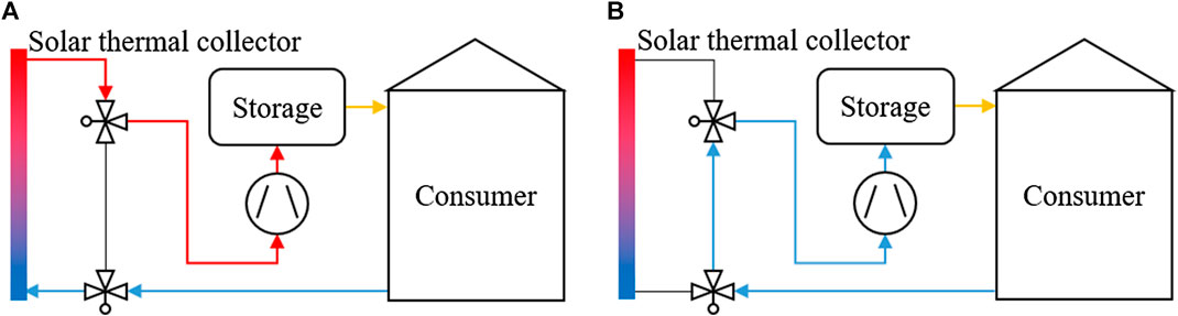
FIGURE 1. Operation modes of a possible latent heat storage system: charging during the day (A) and discharging during the night (B).
In literature, studies of different latent heat storage systems, both experimental and numerical, can be found. Types of latent heat storage include shell-and-tube heat exchangers or direct contact designs as well as packed bed storage tanks. The latter were investigated, among others, by Saitoh and Hirose (1986), Ismail and Henríquez (2002), and Loem et al. (2019). In such systems, the PCM capsules are randomly packed in a tank, and a heat transfer fluid releases heat to the bed while charging or extracts heat while discharging. Storages of structured PCM element arrangements were, for example, described by Darzi et al. (2013). In their numerical study, rectangular, plane PCM plates were used and the influence of operational parameters, such as mass flow rate and inlet temperature, as well as geometrical parameters, such as plate thickness, was investigated. Darzi et al. (2013) found that the plate thickness linearly correlates with the melting duration. Gowreesunker et al. (2013) studied the performance of a PCM plate heat exchanger for air-conditioning of an airport terminal building by using a coupled numerical model. They found that the cooling and partially the heating efforts can be reduced by using PCM and that energy savings of more than 30% can be achieved. The plate encapsulation used in their work was metallic and had surface extensions in form of pin fins in order to increase heat transfer. A recent study of a system consisting of in-duct PCM plates of the same type as used by Gowreesunker et al. (2013) was published by Kumirai et al. (2019). They varied operational parameters, such as inflow velocity and temperature, and compared different PCM in terms of thermal effectiveness. A similar rectangular plate design was investigated by Larrinaga et al. (2020) who investigated the effect of the arrangement of the plate stacks. They found that higher mass flow rates reduce the charging and discharging duration of the storage and that arranging plate stacks in series increases the duration.
Since the performance of the heat storage depends on the ability of the storage elements to effectively transfer energy to the heat transfer fluid, the focus of this study was laid on the design and optimization of new PCM heat storage plates similar to those investigated in the last three studies mentioned above. A new plate design was introduced, which had surface extensions in form of a square based pyramid. The encapsulation material of this plate was high-density polyethylene (HDPE) and the PCM was a salt hydrate. In practice, these plates are stacked and inserted into a box, which has connecting fittings for the installation in air ducts. The plates and the storage box are illustrated in Figure 2. Further, a test rig was set-up in order to evaluate the thermal and pressure drop performance of the plates. Based on the experimental setup, a computational fluid dynamics (CFD) model was developed and validated. Next, this model was reduced in complexity in order to perform a parametric study with respect to several geometry parameters of the plate.
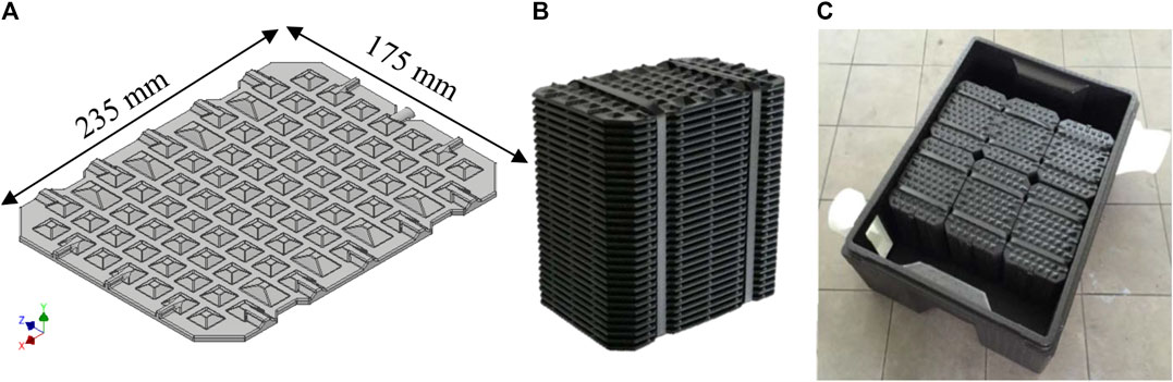
FIGURE 2. The geometric model of a single storage plate (A), a stack of plates (B), and a storage container filled with six stacks of plates (C).
Methods
As can be seen in Figure 2, the PCM plates were designed with an extended surface in the form of a pyramidal frustum. The dimensions of the frustum are 15 mm by 15 mm on the base; the frustum height is 3 mm. The angle between the frustum side faces and the base area is 30°. It should be noted, that the thickness of the plate is constant, which means that the bulges on the top side have similar indentations on the bottom side. The overall thickness of the plate is 5 mm, while the HDPE capsule wall is 1 mm thick, thus resulting in a PCM layer thickness of 3 mm. The PCM volume per plate is around 100 ml. The plates can be stacked up to a variable number, and multiple stacks can be inserted into the container allowing for a variable storage capacity. In order to allow for an improved charging/discharging rate, the surface extensions of the plates were evaluated with the help of CFD.
Experimental
A test rig illustrated in Figure 3 was set-up in order to acquire data for the validation of numerical results. It comprised a duct, in which a stack of ten PCM plates was inserted. Dry air was pumped through the duct by a compressor, then heated and straightened by a filter element before entering the stack. Temperatures were measured with six PT100 class-A sensors with an accuracy of 0.35 K. Two sensors were installed upstream and four sensors downstream of the plate stack in order to determine the thermal performance of the plates under varying inflow temperatures
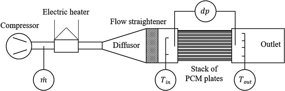
FIGURE 3. Conceptual design of the experimental test rig: measured data include flow rate
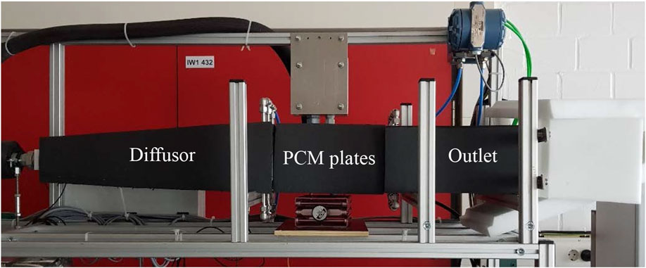
FIGURE 4. The experimental setup.
The PCM used was the salt hydrate ATS30 by the manufacturer Axiotherm GmbH, with a solidus temperature
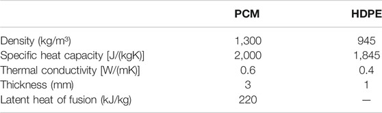
TABLE 1. Properties of PCM and HDPE.
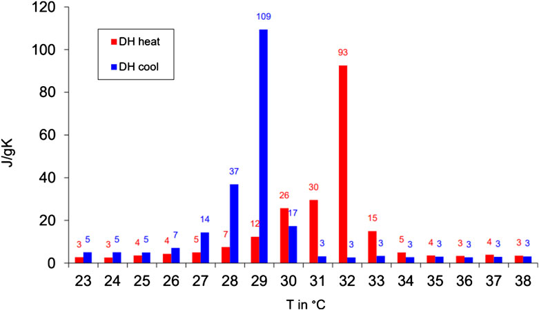
FIGURE 5. Partial enthalpy distribution of the phase change material ATS30 (Axiotherm, 2020).
Computational Fluid Dynamics Model of the Test Rig
In order to optimize the plate design, a simplified CFD model of the air duct containing the plate stack was developed. The simulation tool used to implement the model was STAR-CCM+ 13.04. Due to the symmetry of the plates, only a thin slice section in the center of the stack was modeled, which enabled a significant reduction of the computational effort. The CFD model is illustrated in Figure 6.
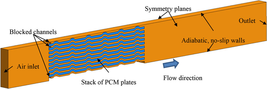
FIGURE 6. Setup of the computational fluid dynamics (CFD) model of a test rig section containing the air duct and the phase change material (PCM) plate stack: air domain (orange) and PCM domain (blue).
The computational model consisted of two domains: air and PCM. The thickness of the capsule walls was not explicitly resolved, rather it was accounted for by applying a thermal resistance at the boundary that separates the air and the PCM. The thermal resistance was determined from the thickness and the thermal conductivity of the HDPE capsule walls (Table 1). At the air inlet, a constant mass flow rate and a specific temperature was defined. Assuming a perfect thermal insulation of the duct, the top and bottom sides were considered as adiabatic, with a no-slip boundary condition. The left and right side of the computational domain were described by symmetry boundary conditions, as shown in Figure 6. At the outlet, zero-gradient boundary conditions for pressure and temperature were applied. Note that due to the particular installation of the plate stack on the test rigs, three channels were blocked, as indicated in Figure 6. In order to properly attach the plates to the test rig, a special console had to be designed, which contained a stack of 10 plates. Since some part of the cross-sectional area of the stack was covered by the console, one plate was removed in the simulation, because no circulation around this plate was expected. However, during the installation of the test rig, it became clear, that more than just one plate was covered by the console. This was accounted for in the model by closing another channel at the top.
Due to relatively low flow velocities, the Mach number was not expected to exceed 0.3. Therefore, the air flow was assumed to be incompressible and modeled by the following governing equations:
Heat transport was described by the energy equation:
Here,
The thermal conductivity
Meshing was performed with polyhedral elements and prism layers near the walls. A grid independence study yielded a mesh element size of 0.1 mm and a time step of 0.5 s as sufficient. Multiple simulations were carried out with flow rates of 150, 275, and 400 L/min. As inlet temperature, the measured inlet temperature curves were used. The temperature and pressure drop were evaluated at the same positions as on the real test rig, upstream and downstream of the plate stack. The simulated outlet temperatures and pressure drops were compared to the measured data.
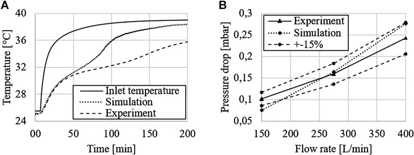
FIGURE 7. Outlet temperatures (A) and pressure drop (B) at a flow rate of 400 L/min.
As can be seen in Figure 7, the simulated outlet temperatures deviate strongly from the measured ones, especially after the start of the phase change process at approximately 50 min. A possible explanation is the thermal mass of the test rig components, such as the diffusor, duct, outlet, etc., which could not be considered in the CFD model. Besides, by simulating only a slice section of the duct geometry, side effects were neglected. Further, the model assumed a perfectly insulated duct, and hence, heat losses to the environment were neglected. These effects lead to a much slower temperature rise in the experiments. Based on these results, we can conclude that it is not practical to model the actual heat transport within the duct. However, the simulated and measured pressure drop values are in good agreement, which indicates that the flow phenomena within the duct are properly captured.
Representative Element for Parametric Study
The simulated flow distribution is shown in Figure 8. It can be seen that the flow pattern inside the individual channels between two plates is similar. This similarity can be used to reduce the initial computational domain to a small representative element.
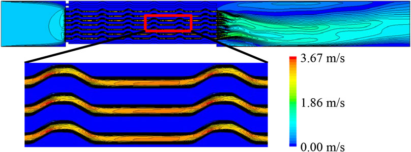
FIGURE 8. Simulated velocity plots of the test rig duct: similar flow patterns can be observed in the channels between the plates.
This element was used to perform a parametric study to identify optimized plate geometries with increased heat transfer and/or lower pressure drop compared to the original design. The model of the representative element, which has the dimensions 10 mm by 40 mm, is illustrated in Figure 9.
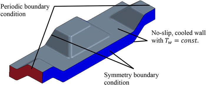
FIGURE 9. Model of a representative channel element.
The phase change phenomena inside the PCM were not modeled, since the actual heat transport into the capsule as well as the pressure drop entirely depend on the actual shape of the capsule surface and operational parameters, such as air flow velocity or inlet temperature. This allows to consider the air flow as steady-state and evaluate the pressure drop and heat transfer under steady-state conditions. By applying a periodic boundary condition at the inlet and outlet of the element, this steady-state was enforced. The wall temperature
In this study, different plate surface geometries were created and evaluated based on their thermo-hydraulic efficiency
In Eq. 6,
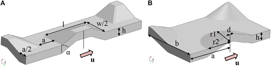
FIGURE 10. Shapes of plate surface elements and their geometrical parameters based on pyramidal frustum (A) and ellipsoid (B).
Results
The influence of some investigated geometrical parameters is shown at the left of Figure 11 for a frustum reference shape with l = w = 12 mm, a = 4 mm, h = 3 mm and α = 45°. Each parameter was changed, while the other were kept constant. Also, combinations were tested, when more than one parameter was changed attempting to find additional local optima. As can be seen in the plots in Figure 11, similar trends in the behavior of both heat transfer coefficient and pressure drop can usually be encountered. For instance, when pressure drop decreases, the heat transfer coefficient decreases as well. However, the slopes are different, and therefore, the optimal compromise between heat transfer and pressure drop can only be found by analyzing the thermo-hydraulic efficiency (Eq. 6). Using this analysis, we found that the frustum based geometries have an improvement potential of only 14% compared to the original.
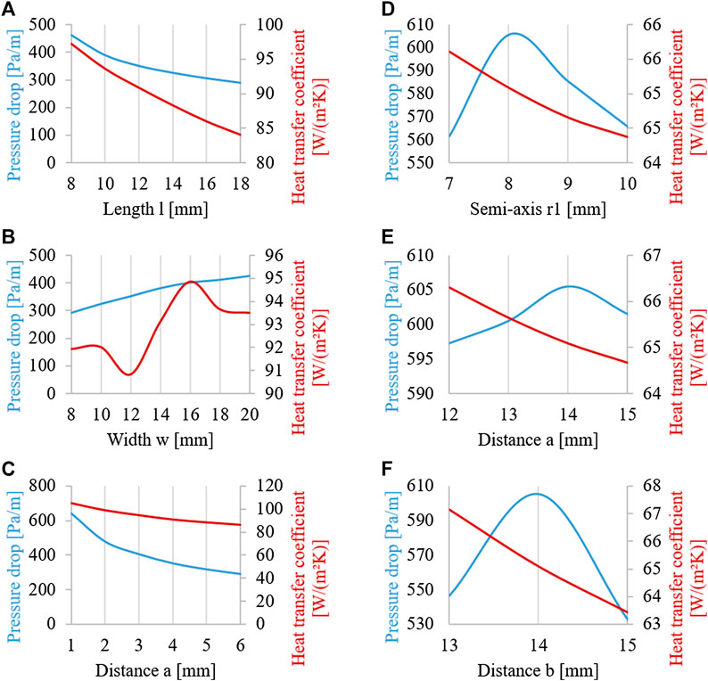
FIGURE 11. Some pressure drop and heat transfer coefficient results of the parametric study for a pyramidal frustum (left) and an ellipsoid (right) based geometry: variation of frustum base length l (A), base width w (B) and distance a between frustums (C) as well as variation of ellipsoid axis r1 (D), distance a (E) and distance b (F).
The same procedure was performed for the ellipsoid based geometries; some illustrative results for a base shape of a = b = 14 mm, h = 3 mm, d = 2 mm, r1 = 6 mm and r2 = 8 mm are shown at the right of Figure 11. As can be seen, the ellipsoidal shapes usually show a maximum of pressure drop, while the heat transfer coefficient decreases with higher geometrical dimensions. The reason for this behavior is the lower surface area available for heat transfer, since with increasing distance between the surface elements, the number of elements per plate decreases. This results in a lower surface area per plate and therefore in reduced heat transfer. The behavior of the pressure drop was somewhat surprising, since we expected its increase together with increasing surface area. However, as can be seen in Figure 11, there is a maximum instead. Such a maximum can also be encountered for other combinations of geometry parameters and geometry variants not shown here, which indicates a higher potential of the ellipsoidal shape for increasing the thermo-hydraulic efficiency. This was indeed confirmed after evaluating 126 different geometry variants based on the ellipsoidal shape, when a possible
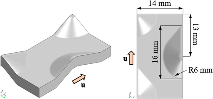
FIGURE 12. The optimized surface element based on the shape of a droplet.
Concluding Remarks
In this work, rectangular, thin heat storage capsules filled with PCM were investigated with respect to their heat transfer performance and pressure drop. The focus was laid on the CFD modeling of the flow and heat transfer in the channels between the plates in order to optimize their shape. Therefore, a test rig was set-up to experimentally evaluate reference plates, and the measured data was used to validate the CFD model of the duct containing a stack of PCM plates. Afterward, the model was reduced in complexity and a representative element was identified, for which a parametric study was performed. Different base geometries were tested as surface extension elements for the storage plates, including pyramidal frustum and ellipsoidal shapes, by changing various geometrical parameters. In total, 217 different geometry variants were simulated and their thermo-hydraulic efficiency was evaluated. Comparing the respective efficiency of each variant with the reference geometry shown in Figure 2, a maximal improvement of 52% was achieved. The optimized shape of surface element based on a droplet shape is shown in Figure 12.
The optimized surface geometry of the representative element can be used for the design of improved PCM plates. For an upcoming project, it is planned to manufacture several of these optimized plates together with a consortium partner and to perform further experimental studies. Besides, the storage container in which the plates are stacked will also be investigated to reach further improvement in order to allow for an even flow distribution. Subsequently, future investigations will involve the performance testing of the optimized plates under real operational conditions in a demonstrator building.
Data Availability Statement
All datasets presented in this study are included in the article.
Author Contributions
All authors listed have made a substantial, direct and intellectual contribution to the work, and approved it for publication.
Funding
The authors are grateful to the German Federal Ministry of Economic Affairs and Energy for their financial support of the project “MoLaWS: Development of a modular heat storage system using high-capacity, innovative latent heat storage elements” (Reference Number: ZF4032917ST7).
Conflict of Interest
The remaining authors declare that the research was conducted in the absence of any commercial or financial relationships that could be construed as a potential conflict of interest.
Acknowledgments
Calculations leading to the results presented here were performed on resources provided by the Paderborn Center for Parallel Computing.
References
Axiotherm GmbH (2020). Data sheet—ATS 30. Available at: https://www.axiotherm.de/de/download/project/productdatasheet/file/14/ (Accessed August 14, 2020).
Billard, F., and Laurence, D. (2012). A robust k-ε-v2/k elliptic blending turbulence model applied to near-wall, separated and buoyant flows. Int. J. Heat Fluid Flow 33 (1), 45–58. doi:10.1016/j.ijheatfluidflow.2011.11.003
Darzi, A. R., Moosania, S. M., Tan, F. L., and Farhadi, M. (2013). Numerical investigation of free-cooling system using plate type PCM storage. Int. Commun. Heat Mass Transf 48, 155–163. doi:10.1016/j.icheatmasstransfer.2013.08.025
Gowreesunker, B. L., Tassou, S. A., and Kolokotroni, M. (2013). Coupled TRNSYS-CFD simulations evaluating the performance of PCM plate heat exchangers in an airport terminal building displacement conditioning system. Build. Environ 65, 132–145. doi:10.1016/j.buildenv.2013.04.003
International Energy Agency (2019). Renewables 2019—market analysis and forecast from 2019 to 2024. Available at https://www.iea.org/reports/renewables-2019/heat. (Accessed June 5, 2020).
Ismail, K. R., and Henríquez, J. R. (2002). Numerical and experimental study of spherical capsules packed bed latent heat storage system. Appl. Therm. Eng 22 (15), 1705–1716. doi:10.1016/S1359-4311(02)00080-7
Kumirai, T., Dirker, J., and Meyer, J. (2019). Experimental analysis for thermal storage performance of three types of plate encapsulated phase change materials in air heat exchangers for ventilation applications. J. Build. Eng 22, 75–89. doi:10.1016/j.jobe.2018.11.016
Larrinaga, P., Diarce, G., Campos-Celador, A., and García-Romero, A. (2020). Parametric characterization of a full-scale plate-based latent heat thermal energy storage system. Appl. Therm. Eng. 178, 115441. doi:10.1016/j.applthermaleng.2020.115441
Loem, S., Deethayat, T., Asanakham, A., and Kiatsiriroat, T. (2019). Thermal characteristics on melting/solidification of low temperature PCM balls packed bed with air charging/discharging. Case Stud. Therm. Eng 14, 100431. doi:10.1016/j.csite.2019.100431
Mitrovic, J., and Maletic, B. (2011). Numerical simulation of fluid flow and heat transfer in thermoplates. Chem. Eng. Technol 34 (9), 1439–1448. doi:10.1002/ceat.201100271
Saitoh, T., and Hirose, K. (1986). High-performance phase-change thermal energy storage using spherical capsules. Chem. Eng. Commun 41 (1–6), 39–58. doi:10.1080/00986448608911711
Keywords: heat transfer, latent heat, heat storage, computational fluid dynamics, phase change material
Citation: Grabo M, Staggenborg C, Philippi KA and Kenig EY (2020) Modeling and Optimization of Rectangular Latent Heat Storage Elements in an Air-Guided Heat Storage System. Front. Energy Res. 8:571787. doi: 10.3389/fenrg.2020.571787
Received: 11 June 2020; Accepted: 31 August 2020;
Published: 09 October 2020.
Edited by:
Theodoros Damartzis, École Polytechnique Fédérale de Lausanne, SwitzerlandReviewed by:
Gerhard Schmitz, Hamburg University of Technology, GermanyAmin Ghobeity, Sheridan College, Canada
Copyright © 2020 Grabo, Staggenborg, Philippi and Kenig. This is an open-access article distributed under the terms of the Creative Commons Attribution License (CC BY). The use, distribution or reproduction in other forums is permitted, provided the original author(s) and the copyright owner(s) are credited and that the original publication in this journal is cited, in accordance with accepted academic practice. No use, distribution or reproduction is permitted which does not comply with these terms.
*Correspondence: Eugeny Y. Kenig, ZXVnZW55LmtlbmlnQHVwYi5kZQ==