 Kenneth E. Okedu
 Hind F. A. Barghash
- 1Department of Electrical and Computer Engineering, National University of Science and Technology, Muscat, Oman
- 2Department of Electrical and Electronic Engineering, Kitami Institute of Technology, Hokkaido, Japan
- 3Department of Environmental Engineering, German University of Technology, Muscat, Oman
The major aim for achieving the successful synchronization of a wind turbine system to the grid is to mitigate electrical and mechanical stresses on the wind generator. During transient state, the gearbox, shaft, and rotor of the wind generator could be damaged due to mechanical stress. The rotor and stator windings of the wind generator, including its insulation, could be affected. This paper undertakes an extensive analysis of the effects of the excitation parameters of the power converter Insulated Gate Bipolar Transistors (IGBTs), on the transient state performance of the Doubly Fed Induction Generator (DFIG), considering different scenarios. The optimal excitation parameters of IGBTs were used for further analysis of the wind generator, considering a new Phase-Locked-Loop (PLL) scheme. The PLL computes the phase displacement of the grid required to achieve orientation and synchronization control. Consequently, it helps in preventing power system distortion due to stator-grid interphase. This paper proposes a new approach that integrates PLL control strategy and a Series Dynamic Braking Resistor (SDBR) to augment the fault ride through capability of a variable speed wind turbine that is DFIG-based. The SDBR helps the post fault recovery of the wind generator. Simulations were run in Power System Computer Aided Design and Electromagnetic Transient state Including DC (PSCAD/EMTDC) to examine severe fault conditions, and to test the robustness of the controllers employed. The results show that the proposed hybrid control strategy aids the fast recovery of the DFIG wind generator variables during fault conditions.
Introduction
In wind energy application, the Doubly Fed Induction Generator (DFIG) has a major advantage because its power converters require only 20–30% of the machine rating, for interfacing the rotor and the grid (Xu and Cartwright, 2006; Okedu, 2019). In addition, the DFIG has cost effective power converters with low power losses, the ability to better capture wind energy, and good active and reactive power regulation in four quadrants, making it widely used compared to other fixed speed wind turbine technology (Okedu, 2020). However, because the power converters of the DFIG wind turbine are fragile, they are vulnerable during grid faults. Consequently, these power converters need to be protected to avoid damage and also to fulfill grid requirements by controlling frequency and voltage via its rotor circuit.
There is a need for wind turbines to possess some level of adaptability to effectively ride through faults. The DFIG usually employs the traditional stator-flux-oriented vector control (Cardenas et al., 2005; Hughes et al., 2005; Qiao et al., 2008; Abad et al., 2010). One of the salient aspects to consider in the DFIG grid connected system control is effective synchronization with the reference grid. The most widely accepted solutions to provide this synchronization are Phase-locked Loop (PLL) techniques (Rodriguez et al., 2007). The traditional control topologies of the DFIG wind generator system take into consideration the amplitude, frequency, and phase angle of the positive-sequence grid voltages. These parameters help in achieving the effective synchronization of the system variables, computing power flux, or changing of state variables into rotating reference frame coordinates (Han et al., 2009).
A common strategy for synchronizing the power converters of a grid-tied DFIG wind turbine is the synchronous reference frame three-phase PLL scheme. This method uses Concordia’s and Park’s transformations to convert the three-phase voltage vector from the natural reference frame to the rotating frame. The traditional PLL method provides good results during operating conditions. However, it is not effective in the presence of unbalanced grid voltages. Due to this shortcoming, various PLL algorithms with different features have been reported in recent literature. One study (Robels et al., 2010) presents a PLL developed using the adaptive linear optimal filter technique. Reference (Liccardo et al., 2011) proposed a PLL scheme based on a filtered-sequence, considering moving average filters and Park transformation, while a standard PLL scheme that is derived considering pq theory and a control method having standard qPLL structure for synchronization, was presented in (Wang and Li 2013). A cascaded delayed signal cancellation three-phase PLL control strategy was reported in (Carugati et al., 2012), based on selective harmonic detection techniques. Two other studies (Ghartemani et al., 2012; González-Espín et al., 2012) reported a PLL based on a variable sampling period for the automatic adjustment of the sampling frequency, and an adaptive synchronous reference frame that used infinite-impulse-response notch filters to reject voltage disturbances, respectively. In (Naves et al., 2010), a PLL based on a generalized delayed signal cancellation was proposed, while in another study (Rodriguez et al., 2012), an integrator frequency-locked loop dual second-order two adaptive filters on a stationary reference frame was presented. An adaptive neural PLL was developed for DFIG synchronization in reference (Ali et al., 2014).
The Series Dynamic Braking Resistor (SDBR) is used to ride through low voltage, much like the traditional crowbar scheme, but with a different topology. The crowbar is shunt in connection and voltage controlled, while the braking resistor is series in connection and current controlled. Resistance enables the high voltage in the braking resistor to be shared, thereby avoiding power converter loss because overvoltage is not induced. A study (Causebrook et al., 2007) improved the performance of induction generator based wind farms by employing SDBR. The DFIG based wind turbine performance was improved during grid fault in (Yang et al., 2010), by connecting the braking resistor in the rotor circuit. Furthermore, in (Okedu et al., 2012; Okedu, 2016) the topology was different because the braking resistor was at the stator circuitry of the wind generator. In the literature, the use of fault current, passive resistance, and antiparallel thyristors for wind generators based on DFIG technology have been reported (Petersson et al., 2005; Yan et al., 2009; Park et al., 2010). Integrating SDBR of small size at the DFIG stator circuit through circuits designed using concepts of power electronics, helps to stabilize the active power of the wind turbine (Okedu et al., 2011). The control strategy of the braking resistor is cheaper compared to other fault ride through topologies.
This study aims to improve the performance of the DFIG-based wind turbine by investigating the effects of the excitation parameters of the power converter insulated gate bipolar transistors (IGBTs) of the DFIG wind turbine during transient state. The excitation parameters of the IGBTs that are investigated include the turn on and turn off resistances, forward break over, and reverse withstand voltages. An extensive analysis of the effects of the excitation parameters of the IGBTs was carried out by considering fifteen scenarios. The IGBT turn on resistance has a significant effect on the responses of the wind generator’s variables, while its turn off resistance has little or minimal effects on the variables of the wind generator. However, the forward break over and reverse withstand voltages of the IGBT has no effects on the performance of the wind generator variables during transient state. The optimal excitation parameters that gave the best responses in the wind generator variables during transient state were used to further analyze the performance of the wind generator. This study proposes a hybrid coordinated control of a new PLL configuration and the SDBR. The proposed PLL control is based on a delayed signal that helps the phase of the positive sequence component be obtained quickly and accurately, despite a disturbance of the grid voltage. Hence, it has a better tracking of the positive components of the grid voltage, compared to the conventional PLL. The SDBR mitigates the overvoltage experienced in the rotor circuitry and the rotor high currents. Thus, the wind generator’s power converter is intact during operation because these actions eliminate the capacitor’s DC-link high charging current, which is dangerous to the power converters. In this paper, the optimum size and placement of the braking resistor in the wind generator were explored to enhance the wind generator during transient state, in conjunction with the proposed PLL scheme for the DFIG wind generator. In addition, a comparative study using the proposed hybrid scheme and the conventional PLL DFIG scheme is presented. The results of the study on proposed control strategies for the DFIG during severe three phase fault scenarios showed better results than the conventional PLL scheme. Simulations were run in PSCAD/EMTDC (PSCAD/EMTDC Manual, 1994).
Model System of Study
The model system of study is shown in Figure 1. The wind turbine is modeled using Eqs. 1–6. The primary components in modeling the wind turbine system consist of the turbine rotor or prime mover, a shaft, and a gearbox unit. The aerodynamic torque and the mechanical power of the wind turbine are given by (Takahashi et al., 2006; Huchel et al., 2015):
Where
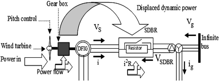
FIGURE 1. DFIG model with SDBR dynamics.
The relationship between
The rotational speed [rad/s] of the wind turbine is
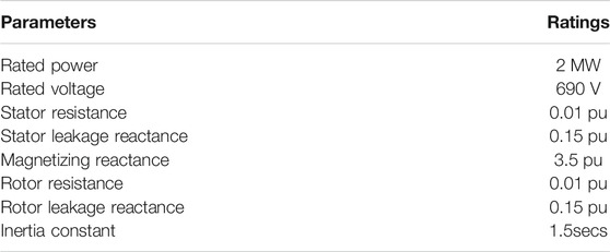
TABLE 1. Parameters of DFIG Wind turbine.
DFIG Variable Speed Drive Control
Figure 2 shows the classical configuration and power flow of a wind generator based on DFIG technology, with bidirectional power converters. The utilization of the voltage source converters in an economical way is one of the important features of this type of wind turbine. This is because, unlike the synchronous wind generators that employ full converter rating, only the power electronic rotor circuitry is required in DFIG wind turbines. During normal operation, the optimal power of the wind generator is achieved by considering wind power. The maximum power point tracking characteristics of the wind generator are directly related to the d-axis reference current. The regulation of the active power of the wind generator is possible via the control of the pitch angle. This is done by frequency control and grid support, based on the power margins provision. From Figure 2, the DC-link voltage is maintained constant at 1.0 pu by the regulation of the quadrature axis current, while the grid voltage is maintained constant at 1.0 pu, by the regulation of the direct axis current. Reactive power dissipation is achieved by the power converters of the wind generator by regulating the grid voltage.
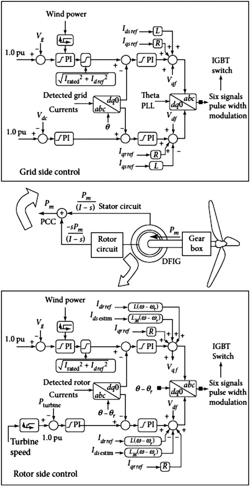
FIGURE 2. DFIG control strategy.
Insulated Gate Bipolar Transistor Excitation Parameters
The schematic diagram of the rotor side converter of the DFIG variable speed wind turbine is shown in Figure 3, with the IGBTs connected. Table 2 gives a summary of the excitation parameters investigated in this study and the respective ratings.

FIGURE 3. DFIG power converter with IGBTs.
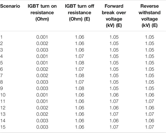
TABLE 2. Excitation Parameters of the insulated gate bipolar transistors.
The turn on and turn off resistances, forward break over, and reverse withstand voltage excitation parameters of the IGBTs were investigated by considering the various scenarios shown in Table 2. The IGBT turn on resistance has many effects on the responses of the wind generator’s variables, while its turn off resistance has little or minimal effects on the variables of the wind generator. These are demonstrated in the simulation results and discussion section of this paper. The forward break over and reverse withstand voltages of the IGBT do not affect the performance of the wind generator variables during transient state. The variation of the forward break over and reverse withstand voltages of the wind generator power converter does not contribute to the wind turbine enhancement during steady state and grid fault conditions. The optimal excitation parameters that gave the best responses for the wind generator variables during transient state, were used for further analysis of the wind turbine considering a new PLL scheme, as described in the subsequent section of this paper.
Conventional and Proposed Phase Lock Loop Schemes for DFIG
Figure 4 shows the conventional three-phase PLL scheme which involves an error signal feedback system considering the rotating frame synchronous principle with oscillator control based on voltage (Justo et al., 2015) and low pass filters. The working principle is based on the conversion of measured voltage of the three phase system to the d-q component, via conversion coordinate and set DC voltage reference of q-axis vref. Figure 5 shows the vector partition diagram for the PLL. From Figure 5, the d-axis component is fully co-phased with the vector voltage when the q-axis component is zero, despite the values of the voltages on the various q-axes. The PI controller in Figure 4 helps to obtain the frequency of the system. With the grid voltage having only positive sequence fundamental components, the d-q steady value coordinate is DC current, and its phase and frequency can be locked by controlling the q-axis component to zero. Frequency detection when the grid voltage is balanced is achieved for the conventional three phase PLL, by tracking the grid voltage positive sequence fundamental components, as the inner of the PLL is a closed loop controller. However, during transient state, there will be a sudden change, giving rise to instantaneous negative sequence and zero sequence fundamental components, which leads to the oscillation of the PLL output angle.
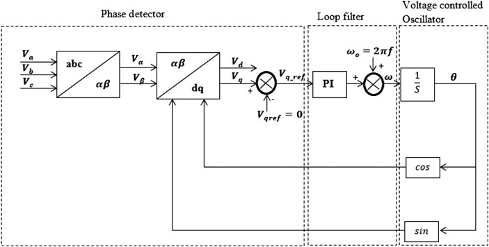
FIGURE 4. Conventional PLL scheme.
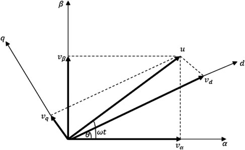
FIGURE 5. PLL vector partition.
In the course of the grid voltage becoming unbalanced, there exist not only positive sequence fundamental components but also negative and zero sequence fundamental components. For a typical three phase system without a neutral point, the zero sequence is not usually considered. Thus, the grid voltage can be expressed as (You-wei et al., 2012).
From Eq. 7, V+, V− gives the voltage amplitude separately for the positive and negative sequences respectively.
The fundamental components of the positive and negative sequences in the static coordinates of αβ grid voltage are given as:
After d-q transformation to the synchronous coordinate system, the following equation is obtained:
Considering Eqs. 11, 12, lead to
The effective working of the PLL requires that ωt ≈ θ, so Eq. 13 can be expressed as
From Eq. 14 it can be seen that for the synchronous coordinate system of positive sequence, the DC components are converted, but for the components based on negative sequences, a value that is twice the frequency component is achieved. This is because the conventional PI controller is used to remove the steady state error, thus the negative voltage will influence the output of the PLL.
For good performance during steady state, the loop filters must have a low cutoff frequency, in the widely used PLL strategy. This is because of the occurrence of negative sequence components during transient state. The proposed PLL strategy in this work (Figure 6) has a delay element (e−sT ) that could help solve this drawback, thereby enabling the faster recovery of the variables of the wind generator after a fault. During fluctuations in the grid, the influence of the negative voltage sequence is greatly suppressed with the help of the delay element.
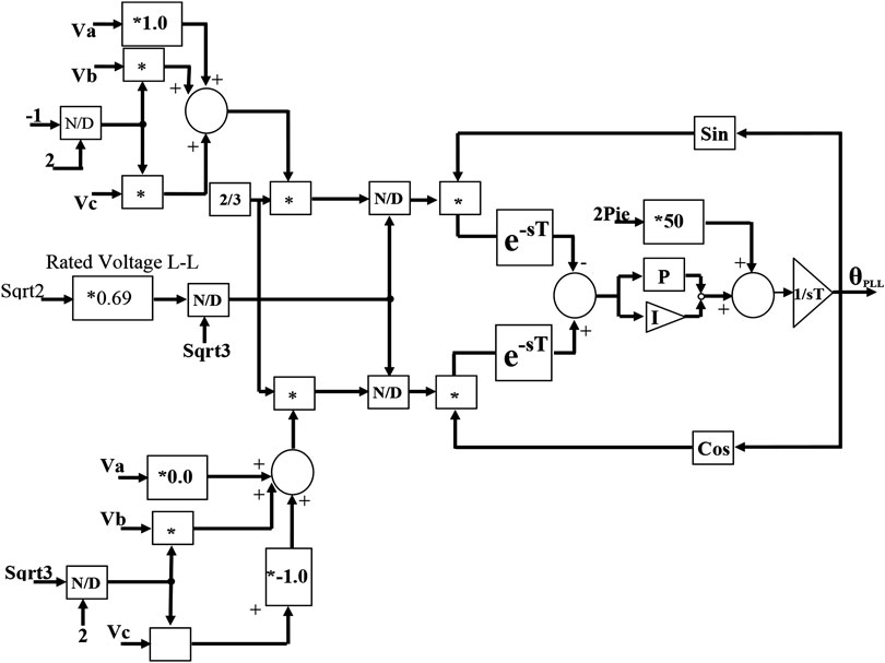
FIGURE 6. Proposed PLL scheme.
From Figure 6, it can be seen that there is a shift of the phase controller in the proposed PLL strategy when compared to the widely used PLL scheme in Figure 4. This phase shift is achieved via the delay element and the disturbances experienced are counteracted, leading to twice the grid frequency based on Eq. 15.
Fault Ride Through Requirements for Wind Farms
Wind farms are faced with a drop in voltage during fault scenarios. Since the grid voltage depends on reactive power injection, recent grid codes require immediate restoration of operation of the wind farms after grid faults, as shown in Figure 7 (E.ON NETZ GmbH, 2006). The grid codes stipulate that within the time frame shown in the figure, the collapse in voltage of the wind farm must be regulated to normal for the wind farm to stay in the grid. Otherwise, the wind farm must be shut down or disconnected.
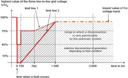
FIGURE 7. E.ON NETZ fault ride through grid code.
Evaluation of the System Performance
A. Effects of the Insulated Gate Bipolar Excitation Parameters on the DFIG
The effects of the excitation parameters on DFIG variable speed wind turbine responses was investigated by considering a severe bolted three phase to ground fault based on the different scenarios given in Table 2. Some of the simulation results of the DFIG variables are presented in Figures 8–16.
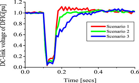
FIGURE 8. DC-link voltage of DFIG.
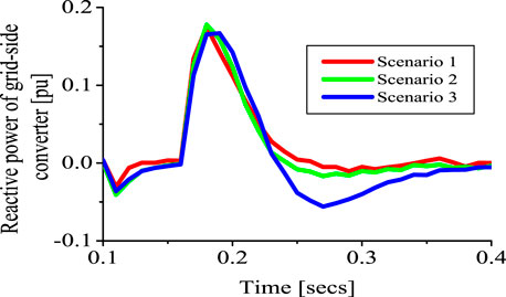
FIGURE 9. Reactive power of DFIG grid side converter.
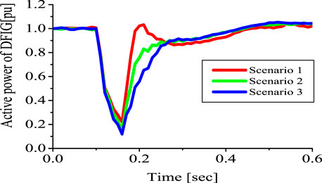
FIGURE 10. Active power of DFIG.

FIGURE 11. Rotor speed of DFIG.
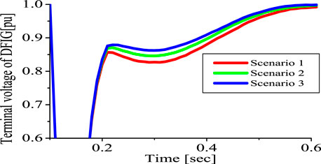
FIGURE 12. Terminal voltage of DFIG.
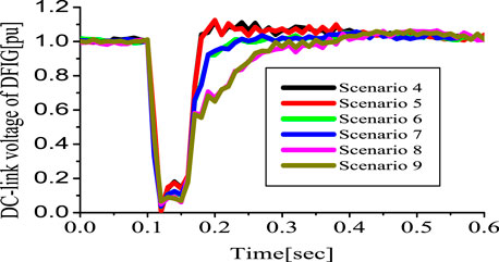
FIGURE 13. DC-link voltage of DFIG.
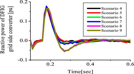
FIGURE 14. Reactive power of DFIG grid side converter.
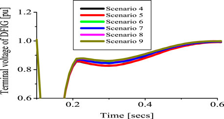
FIGURE 15. Terminal voltage of DFIG.
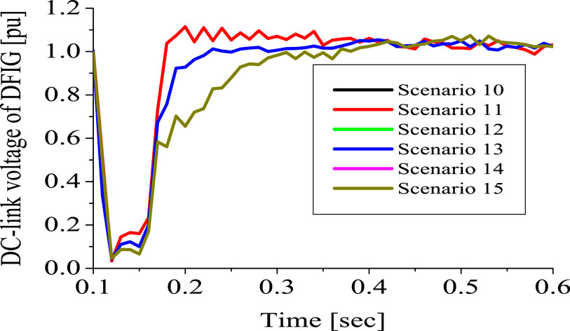
FIGURE 16. DC-link voltage of DFIG.
Figure 8 shows the response of the DFIG wind turbine DC-link voltage for the first three scenarios of Table 2. With a too high IGBT turn on resistance of 0.003 ohms, the DC-link variable of the wind generator did not recover on time, while a too low resistance of 0.001 ohms, gives a faster recovery of the wind generator DC-link voltage. However, there is an overshoot of the DC-link variable considering the low resistance of 0.001 ohms. Thus, a moderate turn on the resistance value of 0.002 ohms for scenario two gives a better performance for the DC-link voltage, the reactive power (Figure 9), and the active power of the wind generator grid side converter shown in Figure 10. Although scenario one tends to have a better performance for the rotor speed response of the wind generator during transient state, as shown in Figure 11. However, the response of the terminal voltage of the wind generator for this scenario, as shown in Figure 12, is lower than that of scenario 2. Thus, a moderate and better response of the DFIG wind generator variables during a severe three phase to ground fault could be achieved, when the turn on resistance of the IGBTs of the power converter is of value 0.002 ohms. It should be noted that, in the investigation of the effects of the turn on resistance of the IGBT, the other excitation parameters were kept constant.
A further analysis was carried out, considering scenarios four to nine outlined in Table 2. As part of this process, the turn on and turn off resistances of the IGBTs were varied while keeping the forward break over voltage and reverse withstand voltage constant, as shown in Figures 13–15, respectively. From Figures 13–15, the turn off resistance of the IGBTs of the wind generator power converter had little or no effects on the responses of the wind generator’s DC-link, reactive power, and terminal voltage during transient state.
To further investigate the effects of the excitation parameters of the IGBTs of the wind generator power converters for the DFIG wind turbine, scenarios 10 to 15 in Table 2 were considered by varying the forward break over voltage and reverse withstand voltage while keeping the turn off resistance of the IGBTs constant, as shown in Figures 16, 17, respectively.
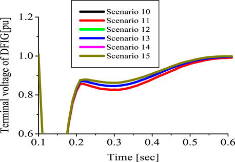
FIGURE 17. Terminal voltage of DFIG.
From Figures 16, 17, it is evident that the forward break over voltage and reverse withstand voltage of the power converter of the IGBTs do not have any effects on the DC-link voltage and terminal voltage variables of the DFIG wind turbine. In light of the above, only the IGBTs turn on resistance had a great impact on the variables of the wind generator. Thus, the optimal value of 0.002 Ω turn on resistance and the IGBTs excitation parameters, considering scenario 2 of Table 2, will be used for further analysis of the new PLL scheme proposed for the DFIG wind turbine, which is discussed in the subsequent section of this paper.
B. Proposed PLL Control Strategy and SDBR Scheme
Based on the optimal performance of the excitation parameters for the power converter IGBTs of the DFIG wind turbine presented in section A, a further investigation was carried out to improve the stability of the DFIG wind turbine using the new PLL scheme in conjunction with the SDBR control strategy. Simulations were run for three scenarios in this section. In the first scenario, the conventional PLL scheme was used for the DFIG wind generator, while the second scenario uses the new PLL scheme for the DFIG wind generator. The combination of the proposed PLL scheme and best control strategies of the SDBR were used in the third scenario to improve the stability of the wind generator during transient state. Some of the DFIG variables for these analyses are shown in Figures 18–20, for a three-phase to ground severe fault.
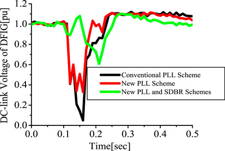
FIGURE 18. DC-link voltage of DFIG.
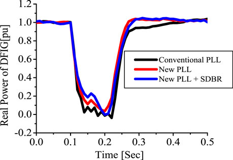
FIGURE 19. Real power of DFIG.
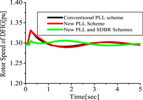
FIGURE 20. Rotor speed of DFIG.
Figure 18 shows the response of the DFIG wind turbine DC-link voltage for the conventional PLL scheme and the new PLL scheme. The figure indicates that the proposed PLL scheme helps in enhancing the performance of the DC-link voltage during transient state with the help of the delay element discussed earlier. A further investigation of using the new PLL scheme and the best working conditions of the SDBR improved the variables of the wind generator during transient state. The reasons for this improved performance are based on the benefits of the SDBR earlier given for the limitation of the rotor overvoltage and current of the rotor circuitry of the wind generator as shown in Figure 18. As a result, the real power and rotor speed are enhanced in Figures 19, 20. The wind turbine power can be improved using the braking resistor because the rotor speed can be limited with few oscillations during fault scenarios, as shown in Figure 20. Therefore, the combination of the proposed PLL scheme and best working conditions and control strategy of the SDBR will improve the post fault recovery of the DFIG wind turbine system variables. A comparison of the proposed PLL scheme to traditional PLL solutions is given in Table 3.
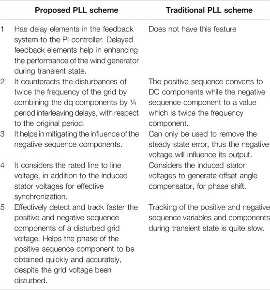
TABLE 3. Comparison of the proposed PLL scheme and other PLL solutions for DFIG.
Conclusion
This paper investigated the performance of a DFIG variable speed wind turbine using a coordinated control strategy for the optimal excitation parameters of the Insulated Gate Bipolar Transistors (IGBTs), a new Phase Lock Loop (PLL), and Series Dynamic Braking Resistor (SDBR) during grid fault. The responses of the DFIG variables during transient state using the hybrid control strategies of the excitation parameters of the IGBTs, SDBR, and the new PLL scheme were better than the conventional PLL scheme. The IGBTs turn on resistance had a significant impact on the DFIG variables during transient state compared to the other excitation parameters such as the turn off resistance, forward break over voltage, and reverse withstand voltage. When the turn on resistance is too high or low, the variables of the wind generator cause overshoot or are too slow to recover after the grid fault. A well sized and positioned SDBR in the stator side of the wind generator was used to enhance the performance of the new DFIG PLL scheme. An optimization approach using Dragon Fly Algorithm is the next phase of this work, which could enhance the performance of the wind generator.
Data Availability Statement
The raw data supporting the conclusion of this article will be made available by the authors, without undue reservation.
Author Contributions
KO did the conceptual design, simulation analysis and writing of the paper. HB did the literature review and sponsorship of the paper.
Conflict of Interest
The authors declare that the research was conducted in the absence of any commercial or financial relationships that could be construed as a potential conflict of interest.
Acknowledgments
Part of this work was presented by the first author at the IEEE International Electric Machines and Drives Conference (IEMDC 2017), Paper ID 115, May 21–24, 2017, Miami, FL, United States, Reference (Okedu 2017). The authors would like to thank the German University of Technology, Oman, for sponsoring this work.
References
Abad, G., Rodriguez, M. A., Iwanski, G., and Poza, J. (2010). Direct power control of doubly-fed-induction-generator-based wind turbine under unbalanced grid voltage. IEEE Trans. Power Electron 25 (2), 442–452. doi:10.1109/TPEL.2009.2027438
Ali, B., Abdeslam, D. O., Cheriff, T. O., and Seddiki, H. (2014). Adaptive neural PLL for grid connected DFIG synchronization. Journal of Power Electronics 14 (3), 608–620. doi:10.6113/JPE.2014.14.3.608
Cardenas, R., Pena, R., Proboste, J., Asher, G., and Clare, J. (2005). MRAS observer for sensorless control of standalone doubly fed induction generators. IEEE Trans. Energy Convers 20 (4), 710–718.
Carugati, I., Maestri, S., Donato, P. G., Carrica, D., and Benedetti, M. (2012). Variable sampling period filter PLL for distorted three-phase systems. IEEE Trans. Power Electron 27 (1), 321–330.
Causebrook, A., Atkinson, D. J., and Jack, A. G. (2007). Fault ride through of large wind farms using series dynamic braking resistors. IEEE Trans. Power Syst 22, 966–975. doi:10.1109/TPWRS.2007.901658
Da Silva, J. L., de Oliveira, R. G., Silva, S. R., Rabelo, B., and Hofmann, W. (2008). A Discussion about a Start-up Procedure of a Doubly-Fed Induction Generator SystemNordic Workshop on Power and Industrial Electronics. Guangzhou, China: NORPIE
E.ON NETZ GmbH (2006). Grid Connection Regulation for High and Extra High Voltage. Winnipeg, Canada, Manitoba HVDC Research Center.
Ghartemani, M. K., Khajehoddin, S. A., Jain, P. K., and Bakhshai, A. (2012). Problems of startup and phase jumps in PLL systems. IEEE Trans. Power Electron 27 (4), 1830–1838. doi:10.1109/TPEL.2011.2169089
González-Espín, F., Figueres, E., and Garcerá, G. (2012). An adaptive synchronous reference-frame phase-locked loop for power quality improvement in a polluted utility grid. IEEE Trans. Ind. Electron 59 (6), 2718–2731. doi:10.1109/TIE.2011.2166236
Han, Y., Xu, L., Khan, M. M., Yao, G., Zhou, L.-D., and Chen, C. (2009). A novel synchronization scheme for grid-connected converters by using adaptive linear optimal filter based PLL (ALOF-PLL). Simulat. Model. Pract. Theor 17 (7), 1299–1345. doi:10.1016/j.simpat.2009.05.004
Huchel, L., El Moursi, M. S., and Zeineldin, H. H. (2015). A parallel capacitor control strategy for enhanced FRT capability of DFIG. IEEE Transactions on Sustainable Energy 6 (2), 303–312. doi:10.1109/TSTE.2014.2371925
Hughes, F. M., Anaya-Lara, O., Jenkins, N., and Strbac, G. (2005). Control of DFIG-based wind generation for power network support. IEEE Trans. Power Syst 20 (4), 1958–1966. doi:10.1109/TPWRS.2005.857275
Jung-Woo, P., Ki-Wook, L., Dong-Wook, K., Kwang-Soo, L., and Jin-Soon, P. (2007). “Control method of a doubly-fed induction generator with a grid synchronization against parameter variation and encoder position,” in Industry applications conference 42nd IAS annual meeting, conference record of 2007 IEEE, New Orleans, LA, September 23–27, 2007 (Piscataway, NJ, IEEE), 931–935
Justo, J. J., Mwasilu, F., and Jung, J. W. (2015). Doubly fed induction generator based wind turbines: a comprehensive review of fault ride through strategies. Renew. Sustain. Energy Rev 45, 447–467. doi:10.1016/j.rser.2015.01.064
Liccardo, F., Morino, P., and Raimondo, G. (2011). Robust and fast three-phase PLL tracking system. IEEE Trans. Ind. Electron 58 (1), 221–231. doi:10.1109/TIE.2010.2044735
Naves, F. A. S., Cavalcanti, M. C., de Souza, H. E. P., Bradaschia, F. E. J. B., and Rizo, M. (2010). A generalized delayed signal cancellation method for detecting fundamental-frequency positive-sequence three-phase signals. IEEE Trans. Power Deliv 25 (3), 1816–1825. doi:10.1109/TPWRD.2010.2044196
Okedu, K. E. (2017). “Optimal position and best switching signal of SDBR in DFIG wind turbine low voltage ride through conditions,” in IEEE International electric machines and drives conference, Miami, FL, May 21-24, 2017 (Piscataway, NJ, IEMDC)
Okedu, K. E. (2020a). Determination of the most effective switching signal and position of braking resistor in DFIG wind turbine under transient conditions, Electrical Engineering 102 (11), 471–480. doi:10.1007/s00202-019-00888-5
Okedu, K. E. (2020b). Improving the transient performance of DFIG wind turbine using pitch angle controller low pass filter timing and network side connected damper circuitry. IET Renew. Power Gener 14 (7), 1219–1227. doi:10.1049/iet-rpg.2019.1124
Okedu, K. E. (2016). Enhancing DFIG wind turbine during three-phase fault using parallel interleaved converters and dynamic resistor. IET Renew. Power Gener 10 (6), 1211–1219. doi:10.1049/iet-rpg.2015.0607
Okedu, K. E. (2019). Enhancing the performance of DFIG variable speed wind turbine using parallel integrated capacitor and modified modulated braking resistor. IET Gener., Transm. Distrib 13 (15), 3378–3387. doi:10.1049/iet-gtd.2019.0206
Okedu, K. E., Muyeen, S. M., Takahashi, R., and Tamura, J. (2012). Wind farms fault ride through using DFIG with new protection scheme. IEEE Transactions on Sustainable Energy 3 (2), 242–254. doi:10.1109/TSTE.2011.2175756
Okedu, K. E., Muyeen, S. M., Takahashi, R., and Tamura, J. (2011). “Improvement of fault ride through capability of wind farm using DFIG considering SDBR,” in 14th European conference of power electronics EPE, Birmingham, United Kingdom, August 30, 2011 (Piscataway, NJ, IEEE), 306
Park, W., Sung, B. C., and Park, J. W. (2010). The effect of SFCL on electric power grid with wind turbine generation system. IEEE Trans. Appl. Supercond 20, 1177–1181. doi:10.1109/TASC.2010.2040918
Petersson, A., Lundberg, S., and Thiringer, T. (2005). A DFIG wind turbine ride through system influence on energy production. J. Wind Energy 8, 251–263. doi:10.1002/we.157
Qiao, W., Zhou, W., Aller, J. M., and Harley, R. G. (2008). Wind speed estimation based sensorless output maximization control for a wind turbine driven a DFIG. IEEE Trans. Power Electron 23 (3), 1156–1169. doi:10.1109/TPEL.2008.921185
Robels, E., Caballos, S., Pou, J., Martin, J. L., Zaragoza, J., and Ibanez, P. (2010). Variable-frequency grid-sequence detector based on a quasi-ideal low-pass filter stage and a phase-locked loop. IEEE Trans. Power Electron 25 (10), 2552–2563. doi:10.1109/TPEL.2010.2050492
Rodriguez, P., Luna, A., Munoz-Aguilar, R. S., Etxeberria-Otadui, I., Teodorescu, R., and Blaabjerg, F. (2012). A stationary reference frame grid synchronization system for three-phase grid connected power converters under adverse grid conditions. IEEE Trans. Power Electron 27 (1), 99–112. doi:10.1109/TPEL.2011.2159242
Rodriguez, P., Pou, J., Bergas, J., Ignacio Candela, J., Burgos, R. P., and Boroyevich, D. (2007). Decoupled double synchronous reference frame PLL for power converters control. IEEE Trans. Power Electron 22 (2), 584–592. doi:10.1109/TPEL.2006.890000
Takahashi, R., Tamura, J., Futami, M., Kimura, M., and Idle, K. (2006). A new control method for wind energy conversion system using doubly fed synchronous generators. IEEJ Trans. Power and Energy 126 (2), 225–235. doi:10.1541/ieejpes.126.225
Wang, Y. F., and Li, Y. W. (2013). Three-phase cascaded delayed signal cancellation PLL for fast selective harmonic detection. IEEE Trans. Ind. Electron 60 (4), 1452–1463. doi:10.1109/TIE.2011.2162715
Xu, L., and Cartwright, P. (2006). Direct active and reactive power control of DFIG for wind energy generation. IEEE Trans. Energy Convers 21 (3), 750–758. doi:10.1109/TEC.2006.875472
Yan, X., Venkataramanan, G., and Wang, Y. (2009). “Grid fault tolerant operation of DFIG wind turbine generator using a passive resistance network,” in Proceedings IEEE-ECCE energy conversion congress and exposition, California, United States, September 20–24, 2009 (Piscataway, NJ, IEEE)
Yang, J., Fletcher, E., and O’Reilly, J. (2010). A series dynamic resistor based converter protection schemes for doubly fed induction generator during various fault conditions. IEEE Trans. Energy Convers 25 (2), 422–432. doi:10.1109/TEC.2009.2037970
Keywords: doubly fed induction generator, phase lock loop, braking resistor, wind energy, stability, bipolar transistors
Citation: Okedu KE and Barghash HFA (2021) Enhancing the Performance of DFIG Wind Turbines Considering Excitation Parameters of the Insulated Gate Bipolar Transistors and a New PLL Scheme. Front. Energy Res. 8:620277. doi: 10.3389/fenrg.2020.620277
Received: 22 October 2020; Accepted: 01 December 2020;
Published: 27 January 2021.
Edited by:
Nestor Francisco Guerrero-Rodriguez, Pontificia Universidad Católica Madre y Maestra, Dominican RepublicReviewed by:
Gabriela Nicoleta Sava, Politehnica University of Bucharest, RomaniaMehdi Firouzi, Islamic Azad University, Iran
Copyright © 2021 Okedu and Barghash.. This is an open-access article distributed under the terms of the Creative Commons Attribution License (CC BY). The use, distribution or reproduction in other forums is permitted, provided the original author(s) and the copyright owner(s) are credited and that the original publication in this journal is cited, in accordance with accepted academic practice. No use, distribution or reproduction is permitted which does not comply with these terms.
*Correspondence: Kenneth E. Okedu, a2Vub2tlZHVAeWFob28uY29tb2tlZHVrZW5uZXRoQG51LmVkdS5vbQ==