 Enhua Wang
 Ningjian Peng
 Mengru Zhang
- School of Mechanical Engineering, Beijing Institute of Technology, Beijing, China
Improving energy efficiency and reducing carbon emissions are crucial for the technological advancement of power systems. Various carbon dioxide (CO2) power cycles have been proposed for various applications. For high-temperature heat sources, the CO2 power system is more efficient than the ultra-supercritical steam Rankine cycle. As a working fluid, CO2 exhibits environmentally friendly properties. CO2 can be used as an alternative to organic working fluids in small- and medium-sized power systems for low-grade heat sources. In this paper, the main configurations and performance characteristics of CO2 power systems are reviewed. Furthermore, recent system improvements of CO2 power cycles, including supercritical Brayton cycles and transcritical Rankine cycles, are presented. Applications of combined systems and their economic performance are discussed. Finally, the challenges and potential future developments of CO2 power cycles are discussed. CO2 power cycles have their advantages in various applications. As working fluids must exhibit environmentally-friendly properties, CO2 power cycles provide an alternative for power generation, especially for low-grade heat sources.
Introduction
Carbon dioxide (CO2) was first patented in 1850 as a refrigerant (Bodinus, 1999). In the 1930s and 1940s, with the advent of chlorofluorocarbons (CFCs), CO2 was gradually replaced. At present, environmental protection is a critical requirement in power system design. Therefore, CO2, as a natural working fluid, attracts attention again (Kim et al., 2004). In 1969, Angelino studied the feasibility of applying a CO2 power cycle for nuclear power generation (Angelino, 1968). Recently, many studies have focused on the CO2 power cycle for high-temperature coal-fired power plants, solar power systems, and low-grade waste heat recovery (Wang et al., 2018b; Lee and Sanchez, 2020).
The average thermal efficiency of standalone CO2 cycles is approximately 40%. However, if a combined cycle is used, the thermal efficiency may rise to 50–60% (Crespi et al., 2017). The supercritical CO2 (sCO2) Brayton cycle has the advantages of high efficiency, compact size, and a moderate operation temperature of 400–750°C. However, the sCO2 Brayton cycle is still at an early stage of deployment. Liu et al. (Liu et al., 2019) reviewed various sCO2 cycles in terms of working fluid properties, structural configurations, applications, thermodynamic and thermoeconomic performances, experimental systems, and main component designs, including turbines, compressors, and printed circuit heat exchangers (PCHEs). Stein and Buck (Stein and Buck, 2017) presented several advanced CO2 power cycles for concentrated solar power (CSP) applications. Wang et al. (Wang et al., 2017) compared six different system layouts with reheating coupled with a molten salt energy storage system. Wu et al. (Wu et al., 2020) analyzed various sCO2 Brayton cycles for small modular reactors, generation IV reactors, and fusion reactors. White et al. (White et al., 2021) summarized the technical and operational challenges of sCO2 power cycles, including turbomachinery and heat exchanger design, material selection, and optimal operation and control methods. Kumar and Srinivasan (Kumar and Srinivasan, 2016) reported the advancements in several transcritical CO2 (tCO2) cycles for solar power generation.
The aforementioned studies primarily focused on sCO2 power cycles or a specific application area. However, recent advancements in system design, the technical challenges, and tCO2 cycles for various applications require further investigation. CO2 power cycles have many different system configurations for different applications. It is necessary to select the most suitable configuration to maximize the performance of a specific application. This paper summarizes the system configurations and operation characteristics of various CO2 power cycles. State-of-the-art technical progress of sCO2 Brayton cycles and tCO2 Rankine cycles are discussed. Applications in combined power systems and economic performance are also discussed. This study can act as a reference for the system design of novel CO2 power cycles.
Thermophysical Properties of CO2
Compared with conventional refrigerants, CO2 as working fluid has the following advantages:
1) non-toxic, non-corrosive, non-flammable, and will not cause an explosion;
2) rich reserves and cost-effectiveness;
3) moderate critical pressure, and good stability in the application temperature range;
4) good compatibility with other materials and lubricants;
5) high density at the supercritical state, small expander volume, and compact heat exchanger;
6) critical temperature and pressure can adapt to a variety of external heat sources;
7) environmentally friendly properties, zero ozone depletion potential (ODP), global warming potential (GWP) is 1;
8) thermodynamic and transport properties of CO2 are known, which are conducive to power cycle design;
9) high thermal stability, high-temperature heat exchanger (directly exchange heat with a heat source to reduce heat loss), low system complexity.
High precision is crucial for the estimation of thermophysical properties. Generally, the Span and Wagner equation of state (EoS) is used, which has an uncertainty of 0.03–0.05% in density, 0.03–1% in the speed of sound, and 0.15–1.5% in heat capacity (Span and Wagner, 1996; Span and Wagner, 2003). Additionally, the EoSs of Kunz and Wagner (Kunz et al., 2007), MBWR, and FEQ (Schmidt-Wagner) (Ely et al., 1987) can be used to calculate the properties of mixtures containing CO2. Table 1 lists the important thermophysical properties of CO2 at the critical point. A review of the thermodynamic and transport properties of supercritical CO2 can be found in Nikolai et al. (Nikolai et al., 2019). Because the thermophysical properties of CO2 in subcritical and supercritical states differ significantly, the thermodynamic state of a CO2 power cycle at the pump inlet should be designed accordingly so that it is not too close to the critical point. Figure 1A shows the curves of density, isobaric specific heat capacity, thermal conductivity, and viscosity of CO2 at a pressure of 9 MPa. These properties fluctuated significantly near the critical point. Figure 1B shows the curves of the isobaric specific heat capacity under different pressures. Near the critical point, the specific heat capacity increased rapidly. In power cycles using pure CO2 as the working fluid, impurities in CO2 may affect the performance of the compressor and cooler (Vesely et al., 2019). Therefore, the impurity concentrations should be less than 1%.
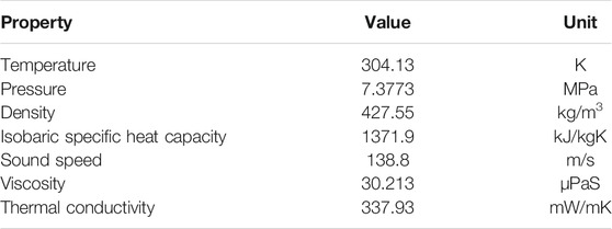
TABLE 1. Thermophysical properties of CO2 at the critical point.
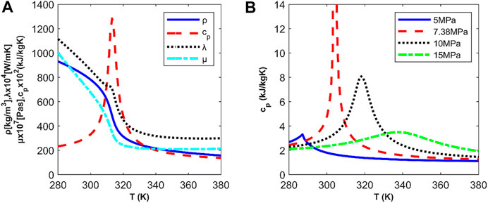
FIGURE 1. Thermophysical properties of CO2: (A) Pressure is 9 MPa; (B) Isobaric specific heat capacity under different pressures.
The variations in the thermophysical properties significantly affect the heat transfer calculation. It is important to select an appropriate heat transfer correlation based on the working conditions of CO2. For shell-and-tube heat exchangers, the Krasnoshchekov-Protopopov correlation (Petukhov, 1970) can be used. The heat transfer of single-phase CO2 in the subcritical state can be estimated using the Petukhov correlation (Petukhov et al., 1961). The convective heat transfer coefficient of the gas-liquid flow can be obtained using the Cavallini-Zecchin correlation (Cavallini and Zecchin, 1974). The pressure drop of CO2 in the condenser can be determined using the Kedzierski-Goncalves correlation (Kedzierski and Goncalves, 1999). Reznicek et al. (Reznicek et al., 2020) evaluated the predicted error of heat transfer, which was within 5%, and the error in the pressure drop was less than 10%. Recently, PCHEs have been used to exchange heat between supercritical CO2 and high-temperature heat sources. The convective heat transfer coefficient in a PCHE can be calculated using the Gnielinski correlation (Dostal et al., 2004; Carstens et al., 2006).
CO2 is not flammable and can be used as a retardant to suppress the flammability of hydrocarbons. Therefore, CO2 is useful for applications with strict safety requirements. Generally, when the mole fraction of CO2 in a mixture reaches 30%, the mixture is non-combustible (Drysdale, 1999). Therefore, some power cycles use zeotropic mixtures containing CO2 and organic fluids to control the flammability while maintaining high efficiency. Mixtures such as CO2/R161(C2H5F), CO2/R1234ze(CF3CH=CHF), and CO2/R134a(CH2FCF3) are not sensitive to variations in the CO2 fraction, while the net power outputs of some mixtures may gradually decrease with an increase in the CO2 fraction (Sánchez and da Silva, 2018). The CO2 fraction also affects the heat transfer area. The glide temperature should be constrained within a reasonable range. A high glide temperature may cause separation of the mixture and reduce its thermodynamic performance (Chys et al., 2012).
Configurations of CO2 Power Cycles
CO2 power systems are classified as closed supercritical Brayton cycles and transcritical Rankine cycles. Supercritical CO2 is cooled in the sCO2 Brayton cycle, while it is condensed to a subcritical state in the tCO2 Rankine cycle. The performance of the CO2 power cycle can be improved by pre-cooling, intercooling, reheating, pre-compression, and recompression. Generally, sCO2 Brayton cycles are divided into single-flow and split-flow configurations. Figure 2 shows the fundamental single-flow layouts, where recuperation, intercooling, reheating, inter-recuperation, pre-compression, and split expansion are employed. The recuperation configuration can effectively utilize the waste heat at the turbine outlet to improve thermal efficiency. Intercooling can reduce the input power of the compressor. Reheating can increase the expansion work of turbines.
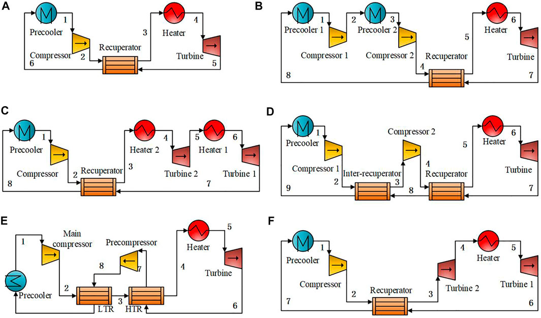
FIGURE 2. Configurations of single-flow sCO2 Brayton cycles: (A) Recuperation; (B) Intercooling; (C) Reheating; (D) Inter-recuperation; (E) Pre-compression; (F) Split expansion (adapted from (Ahn et al., 2015)).
The configurations of split-flow sCO2 cycles are shown in Figure 3. Recompression, modified recompression with pre-compression, pre-heating, and five different turbine split-flow configurations are displayed. The cooling pressure of the sCO2 Brayton cycle is greater than 7.38 MPa, leading to a small expansion ratio. However, the temperature at the turbine outlet is still very high. To further improve the utilization efficiency of this part of waste heat, two-stage recuperation and pre-compression can be adopted based on a single-channel configuration or a split-flow configuration with split expansion. For the recompression configuration, a fluid with a low flow rate and high specific heat at the cold side, after the split flow, can exchange heat fully with the fluid with a high flow rate and low specific heat at the hot side inside the low-temperature regenerator. Thus, the pinch-point problem is alleviated, and the system thermal efficiency is improved. For the modified recompression cycle with pre-compression, the working fluid continues to expand to a subcritical state from the turbine outlet to increase the expansion work and then compresses the working fluid to a supercritical state. The working fluid flow is split between the low-temperature recuperator and high-temperature recuperator for the configurations of turbine split flow. Hence, the energy at the outlet of turbine 1 can be comprehensively utilized. For the pre-heating cycle, turbine split flows IV and V, two heaters are installed, which are suitable for applications with two different heat sources.
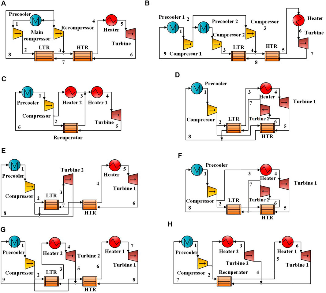
FIGURE 3. Configurations of split-flow sCO2 Brayton cycles: (A) Recompression; (B) Modified recompression; (C) Pre-heating; (D) Turbine split flow I; (E) Turbine split flow II; (F) Turbine split flow III; (G) Turbine split flow IV; (H) Turbine split flow V (adapted from (Ahn et al., 2015)).
Typical configurations of single-flow and split-flow sCO2 cycles were analyzed in Ahn et al. (Ahn et al., 2015). For a high-temperature heat source with a large specific heat capacity, the recompression cycle exhibited high thermal efficiency. Based on a heat source of 545°C from a sodium-cooled fast reactor, the performances of these configurations were compared, and the thermal efficiency of the recompression cycle was the highest at 43.83%. For CSP applications, the recompression sCO2 cycle also exhibited high performance. However, for a heat source with a small heat capacity, the recompression cycle is not the best option. For exhaust heat recovery from a gas turbine, an investigation indicated that the performance of the pre-heating cycle was better than that of the single-stage recuperated cycle and the recompression cycle (Ayub et al., 2018). Even when the recompression cycle was used, the pinch-point problem persisted because of the large temperature variation of the exhaust gas and the small temperature variation of CO2 in the heater. Therefore, it is important to match the heat sources. When a split expansion is introduced, a part of the working fluid flows into the high-pressure expander (Huang et al., 2016). Manente et al. (Manente and Costa, 2020) investigated three configurations of the sCO2 Brayton cycle, including the turbine flow I, turbine flow II, and the pre-heating cycle. The overall heat recovery efficiency of the turbine flow II cycle reached 22.3% for a heat source of 600°C. The split expansion configuration with reheating and intercooling is also helpful for improving the performance (Cho et al., 2015; Kim et al., 2016).
The boundary conditions reported in existing literature for single-flow layouts, including the maximum temperature and pressure, expansion pressure ratio, thermal efficiency, and net power, are listed in Table 2. Figure 4 provides a more intuitive comparison. The diameter of each circle is proportional to the thermal efficiency or net power. The maximum pressure at the turbine inlet was less than 30 MPa, while a maximum pressure of 53.35 MPa was used for theoretical analysis. The maximum temperature was 828°C. Generally, the thermal efficiency improves as the maximum temperature of sCO2 increases. The simple sCO2 cycle has a relatively lower thermal efficiency than the other layouts and is comparable only when the maximum temperature is small. The boundary conditions for the split-flow layouts are presented in Table 3 and Figure 5. The maximum temperature was primarily in the range of 450–650°C, and the maximum pressure was between 20 and 25 MPa. The architectures of these split-flow cycles are complicated and more suitable for large power devices with MW- or even GW-class power output. The results for the thermal efficiency of the recompression cycle cover the range of the other layouts, indicating that the split-flow layouts are well suited for high-temperature applications with a single heat source.
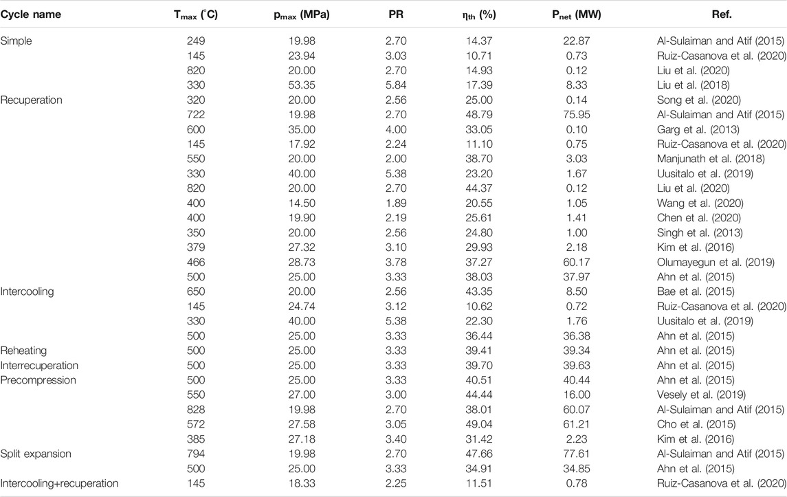
TABLE 2. Boundary conditions of sCO2 cycles with single-flow layouts.
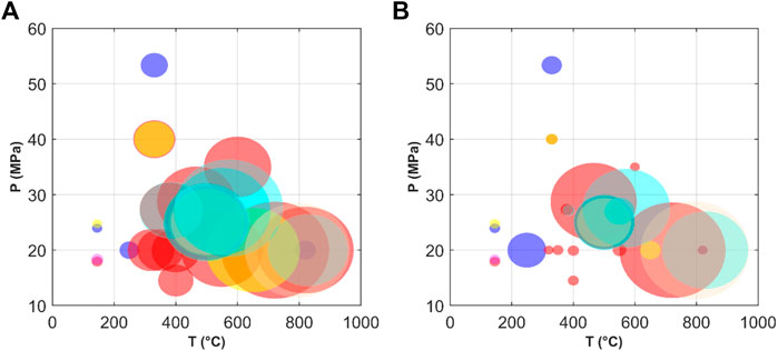
FIGURE 4. Boundary conditions of single-flow sCO2 cycles as a function of the maximum operation temperature and pressure: (A) Thermal efficiency; (B) Net power output (legend:  simple
  recuperation
  intercooling
  reheating
  inter-recuperation
  pre-compression
  split expansion
  intercooling+recuperation).
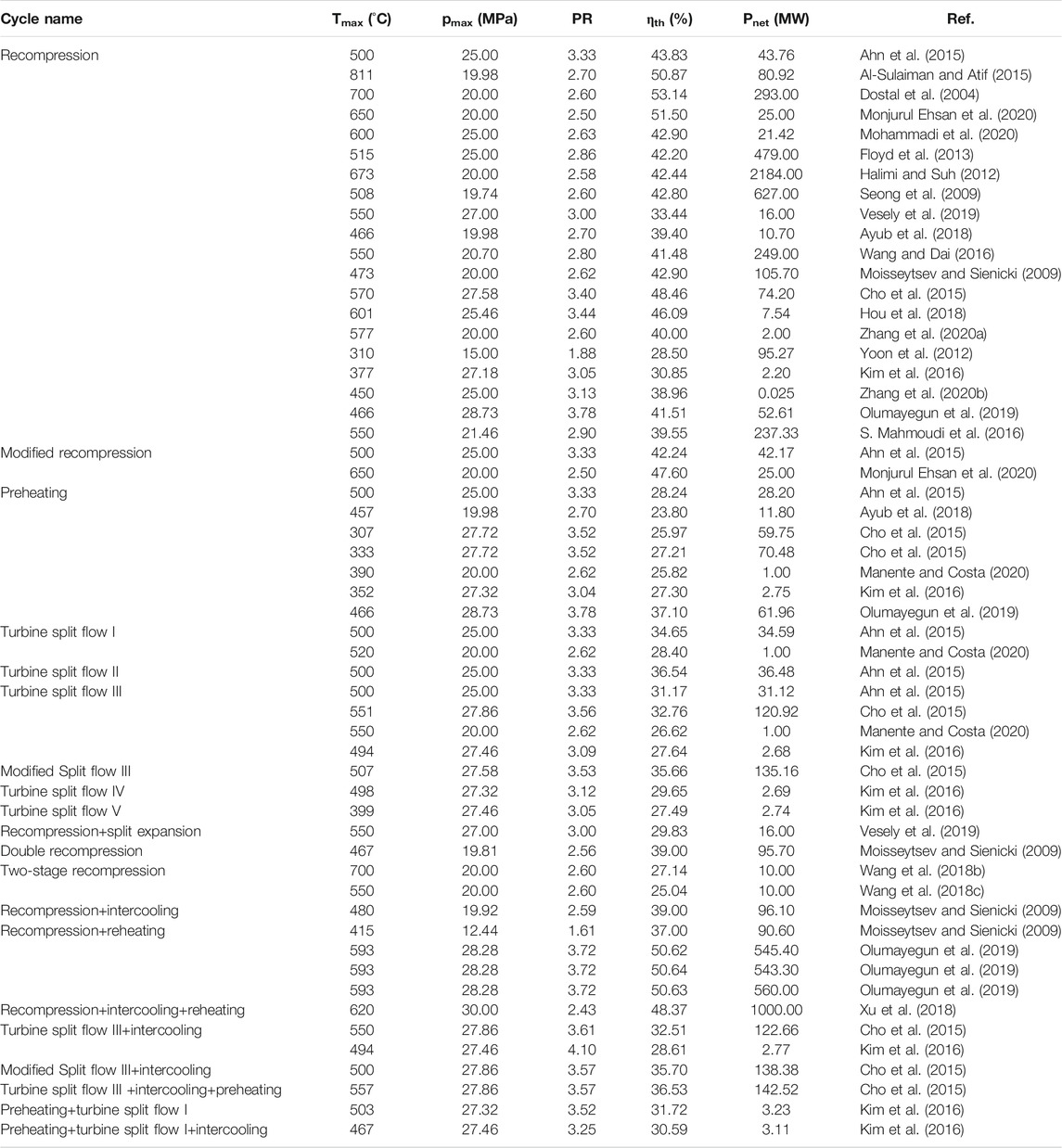
TABLE 3. Boundary conditions of sCO2 cycles with split-flow layouts.
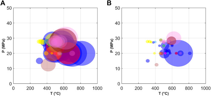
FIGURE 5. Boundary conditions of split-flow sCO2 cycles as a function of the maximum operation temperature and pressure: (A) Thermal efficiency; (B) Net power output (legend:  recompression
  modified recompression
  pre-heating
  turbine split flow I
  turbine split flow II
  turbine split flow III
  turbine split flow IV
  turbine split flow V
  combined cycle).
Typical sCO2 cycles are compared in Tables 4, 5. There are four ways to improve the system performance, as shown in Figure 6. The recuperated cycle is a basic improvement of the simple configuration. The recompression cycle and the turbine split flow II are designed to improve the regeneration effect. If the compression process is considered, the intercooling cycle and the inter-recuperated cycle are optimum improvements. The expansion process can be enhanced via the pre-compression cycle or the recompression cycle with pre-compression. If the heating process is considered, the other five configurations can be employed to improve heat transfer. There is no single configuration that is well suited for all applications. During the system design process, specific operation situations, temperatures of the heat source and sink, system size, and cost should be considered. A comparison of different configurations must be performed, and the most appropriate configuration should be chosen.
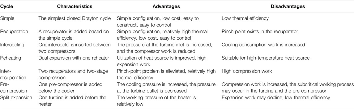
TABLE 4. Comparison of single-flow sCO2 cycles.
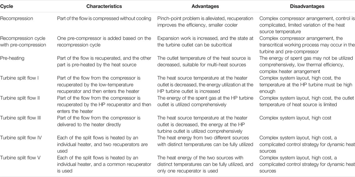
TABLE 5. Comparison of split-flow sCO2 cycles.
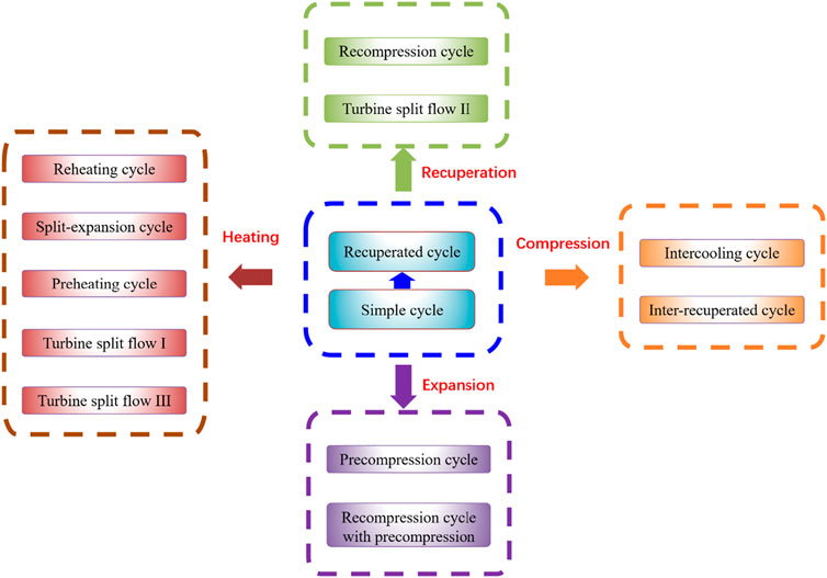
FIGURE 6. Improvement paths for sCO2 Brayton cycles.
In the tCO2 Rankine cycle, CO2 is condensed through a heat sink. Generally, the tCO2 Rankine cycle is used when the ambient temperature is lower than the critical temperature of CO2. The thermal efficiency of a tCO2 Rankine cycle can approach or even exceed that of a traditional Rankine cycle as the turbine inlet temperature increases. Furthermore, the structure of the CO2 Rankine cycle is simpler and more compact. For low-temperature heat sources, the system configurations of the tCO2 cycle are relatively simple. The boundary conditions reported in the existing literature for tCO2 cycles are listed in Table 6, and are also plotted in Figure 7. The maximum temperature for the simple tCO2 cycle was less than 130°C. However, the temperature range for the recuperation cycle covered a large interval of up to 820°C. Accordingly, the thermal efficiency of the recuperation layout was much higher in the high operation temperature regions. The efficiency of the other cycles showed no evident advantages over the recuperation cycle. At present, most studies on tCO2 cycles are mainly focused on small power devices with a power output of 200–600 kW. The characteristics of the four configurations (Meng et al., 2019) are compared in Table 7. For the simple configuration and the regenerative cycle with an open-feed heater, the thermal efficiencies increased significantly with an increase in the inlet temperature of the expander and for a large inlet pressure of the expander. For the reheating cycle, the inlet temperature of the expander had a negligible effect on the thermal efficiency. For the regenerative cycle, the allowable range of the expander inlet pressure was relatively narrow when the inlet temperature of the expander was low.
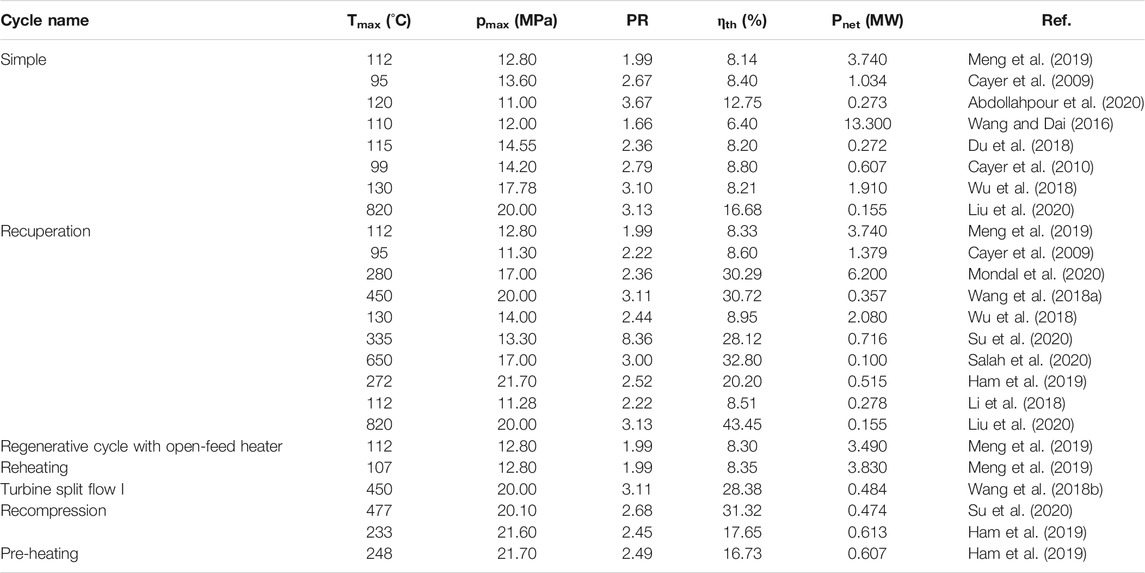
TABLE 6. Boundary conditions of tCO2 cycles.
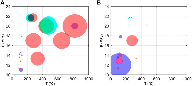
FIGURE 7. Boundary conditions of tCO2 cycles as a function of the maximum operation temperature and pressure: (A) Thermal efficiency; (B) Net power output (legend:  simple,
  recuperation,
  regenerative cycle with open-feed heater
  reheating
  turbine split flow I
  recompression
  pre-heating).
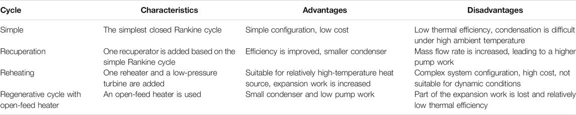
TABLE 7. Comparison of tCO2 Rankine cycles for low-temperature sources.
Performance Characteristics of CO2 Power Cycles
The temperature and pressure of supercritical CO2 at the inlet of the high-pressure turbine are the two key parameters affecting the system performance. With an increase in the turbine inlet temperature, the system efficiency gradually increases, especially when the turbine inlet temperature is low (Chen et al., 2005). However, the maximum temperature at the turbine inlet is limited by the heat source temperature. Furthermore, the condensation temperatures and efficiencies of the turbine and pump have significant influences. For a simple CO2 power cycle, the system efficiency increases proportionally with improvements in the turbine efficiency. The variations in the pump efficiency also have a significant effect owing to the large mass flow rate of CO2. As the expansion ratio increases, the system efficiency first increases and then decreases. This is because the pump consumes more power if the expansion ratio is too large. Therefore, the optimal expansion ratio should be determined. Additionally, not only the thermodynamic performance but also other indexes such as system volume, cost, economy, safety, toxicity, and durability must be evaluated. Multi-objective optimization methods should be used to optimize the working parameters of the CO2 power cycle. There is no single set of working parameters that can optimize all indexes simultaneously (Cayer et al., 2010). As the inlet temperature of the compressor increases, the power consumption of the compressor increases and the thermal efficiency of the sCO2 cycle decreases gradually. Thus, the inlet temperature of the compressor should be close to the critical temperature. However, small variations in the working pressure and temperature can cause apparent changes in the thermal and physical properties of CO2. The power consumption fluctuates abruptly around the critical point. Therefore, the temperature at the compressor inlet should not be too close to the critical point (Liu et al., 2020).
CO2 turbines have some advantages, such as smaller size, less leakage, and shock loss. The turbine size of a sCO2 cycle is significantly smaller than that of a subcritical organic Rankine cycle (ORC). On the other hand, operating conditions for higher speed and greater pressure require a higher mechanical strength of the turbo-generator, especially for the bearing and seal design. The choice of working fluid also affects the geometric parameters of the turbine (Uusitalo et al., 2019). For the turbine, the Stodola elliptic formula (Cooke, 1984) is normally adopted. A one-dimensional mean-line model is used to provide a more accurate estimation of turbine efficiency (Modi et al., 2015; Peng et al., 2020). Three different mean-line models were compared for a CO2 turbine (Lee and Gurgenci, 2020). The total turbine loss based on the Aunger model (Aungier, 2006) was almost the same as the Moustapha model (Moustapha et al., 2003). However, a higher loss was observed in the Whitfield-Baines model (Whitfield and Baines, 1990) because of the large flow rate inside the rotor.
Air cooling is not suitable for steam Rankine cycles. However, air cooling has some advantages in sCO2 power cycles, such as a smoother temperature match profile, lower exergy loss, smaller corrosion and scale deposition, and sediment accumulation. For CSP systems, the sCO2 cycle using air cooling can save a large amount of water, which is critical in inland regions. When the ambient temperature is high, hybrid cooling combing air and water is another option that can reduce performance degradation (Ehsan et al., 2020).
Applications of sCO2 Cycles
In this section, recent progress in sCO2 cycles in nuclear and coal-fired power plants, waste heat recovery, concentrated solar systems, and geothermal power devices are presented.
Nuclear Reactor
The recuperated sCO2 cycle is often used in high-temperature gas-cooled reactors, which have high thermal efficiency, relatively low turbine inlet temperature, compact size, and simple layout (Yoon et al., 2012; Bae et al., 2015). However, the heat transfer rate in the recuperator is limited by the pinch point (Utamura, 2010). In the last two decades, MIT carried out many investigations on sCO2 power cycles for nuclear reactors and obtained some significant results. To improve the performance, a recompression cycle has been proposed, and the split-flow arrangement can effectively alleviate this issue. Based on a 600 MW reactor, Dostal et al. (Dostal et al., 2004) analyzed the performance of a recompression sCO2 cycle. The turbine efficiency is not sensitive to variations in the working pressure and temperature because of the large and almost invariant mass flow rate in this cycle (Zhang et al., 2020a). However, the real gas effect of supercritical CO2 should be considered when designing CO2 turbines (Lee et al., 2012).
The recompression sCO2 cycle can be applied to a fourth-generation sodium-cooled fast reactor. Thus, the risk of a chemical reaction between Na and water in the conventional steam Rankine cycle is avoided. KAERI designed a recompression sCO2 cycle based on the KALIMER 600 system. The rated power was 600 MW. Two centrifugal compressors and a four-stage axial turbine were designed. The estimated thermal efficiency was 42.8% (Seong et al., 2009). The recompression sCO2 cycle is also promising for fusion reactors. The estimated thermal efficiency was 42.44%, as reported by Halimi and Suh (Halimi and Suh, 2012). In the recompression cycle, the flow-split ratio is an important parameter. As the flow-split ratio declines, the cycle efficiency increases. However, the heat transfer area of the low-temperature recuperator also increases. Therefore, the flow-split ratio should be selected based on a trade-off between these two factors (Cha et al., 2009). Although the recompression cycle has a higher efficiency than other configurations, investigations indicate that further improvement of the recompression cycle is difficult (Moisseytsev and Sienicki, 2009).
Supercritical CO2 in a nuclear reactor exhibits very high pressure, which is not conducive to the safety of commercial plants. The working pressure of current nuclear reactors is below 15 MPa although it can be as high as 25 MPa. The maximum working pressure can be decreased by combining the split expansion cycle with the recompression cycle while maintaining a high efficiency level. An investigation showed that the thermal efficiency of the system decreased slightly from 43.88 to 43.11% with a small increase in the heat transfer area, when the inlet temperature of the high-pressure turbine was reduced to 390°C, and the inlet pressure decreased from 20 to 15 MPa (Guo et al., 2018).
For the recompression cycle, the temperature at the inlet of the main compressor is higher than that of the recompressor. If the compressors maintain a constant speed, the split ratio declines as the ambient temperature increases, leading to an apparent decrease in performance. Thus, a proper control strategy is required to maintain high performance under off-design conditions (Floyd et al., 2013). However, the thermophysical properties of supercritical CO2 vary greatly around the critical point, making it difficult to maintain control precision. Generally, control strategies such as constant flow rate and constant reactor outlet temperature are adopted. However, the reactor outlet temperature is low under small-load conditions if a constant flow rate strategy is employed. Furthermore, the system parameters fluctuate greatly, and the transient response time is long when a constant reactor outlet temperature is maintained. An optimal control strategy based on the operating parameters of the compressor was designed by Du et al. (Du et al., 2020a), and the response time of the system was shortened.
Coal-fired Power Plant
The steam Rankine cycle is a popular technology used in coal-fired power plants. To improve energy efficiency, an ultra-supercritical steam Rankine cycle with two-stage reheating is under development. However, owing to the limitations of the material and other technical constraints, the efficiency improvement of the ultra-supercritical steam Rankine cycle has stagnated. Investigations suggest that the sCO2 Brayton cycle is a feasible alternative technology. Recently, the application of sCO2 cycles to coal-fired power plants has attracted significant attention. Li et al. reviewed various applications of sCO2 cycles for pulverized coal power plants, circulating fluidized bed devices, and oxy-coal power systems (Li et al., 2020).
The working temperature of the sCO2 cycle for a coal-fired power plant can be as high as 900°C; the recompression cycle is ideal for this. Reheating is also a useful approach in this regard. Zhou et al. (Zhou et al., 2018) analyzed the performance of a recompression cycle with reheating and two-stage intercooling. Compared with the original 1000 MW single-stage reheating ultra-supercritical steam Rankine cycle (605°C/603°C/274 bar), the optimized thermal and exergy efficiencies of the sCO2 cycle reached 47.64 and 81.25%, respectively. However, the flow rate of CO2 increased significantly, resulting in an excessive pressure drop in the heat exchange process in the boiler, which made it difficult to fully utilize the flue gas energy. Xu et al. designed a partial-split strategy to halve the flow rate and length of the heat exchangers in the boiler (Xu et al., 2018). As a result, the overall pressure drop was reduced to 1/8. Furthermore, the exhaust temperature of the flue gas was reduced to below 120°C by diverting part of the working fluid after intercooling to recover the waste heat of the flue gas. Based on this strategy, a 1000 MW sCO2 power generation system was proposed (Sun et al., 2018). A cascade system was designed to comprehensively utilize the waste heat of flue gas in a large temperature range of 120–1500°C. The top cycle was a recompression sCO2 cycle with two-stage reheating, whereas the bottom cycle was a conventional recompression cycle. The heat addition of the bottom cycle can be regulated by adjusting the flow distribution between the top and bottom cycles. When the maximum working temperature was set to 620°C with a maximum pressure of 30 MPa, the cycle thermal efficiency and power generation efficiency reached 51.22% and 48.37%, respectively. In addition, Zhao found that the most energetic, promising Brayton cycle, among 1000 alternatives, was a double reheating-double recompression-reheating layout, which had a cycle efficiency of up to 51.4% (Zhao, 2018).
Coal-fired power plants are the main source of CO2 emissions. Integration with carbon capture and storage devices is useful for alleviating the greenhouse gas effect. A two-stage cascade sCO2 cycle with a carbon capture unit was evaluated by Olumayegun et al. (Olumayegun et al., 2019). The top cycle was a recompression configuration with one-stage reheating, and the bottom one was a recompression cycle. The carbon capture unit was a CO2 capture system based on monoethanolamine solvent. CO2 was absorbed by the adsorption tower and then dissociated in the separation column. The system thermal efficiency was 3.34–3.86%, higher than that of the traditional steam power cycle. After using the carbon capture unit, the thermal efficiency decreased by 11.2% but was still 0.68–1.31% higher than that of the traditional steam power cycle with carbon capture.
Waste Heat Recovery
A CO2 cycle can be used as the bottom cycle to recover the exhaust heat of a heat engine, such as a gas turbine or internal combustion engine, and the overall energy efficiency can be improved. Hou et al. (Hou et al., 2018) designed a combined cycle consisting of a gas turbine, a recompression sCO2 cycle, a steam Rankine cycle, and an ORC with a zeotropic working fluid. Compared with the traditional gas-steam combined system, the efficiency of the new combined system was increased by 2.33%. In marine applications, the combined power cycle can be coupled with the refrigeration cycle, and the energy efficiency of the entire system can be enhanced further. A CO2 power system was integrated with a compression refrigeration cycle using CO2 as the working fluid (Manjunath et al., 2018). The exhaust heat of the gas turbine was used to drive the regenerative sCO2 cycle. The precooler of the sCO2 cycle was integrated with the cooler of the compression refrigeration cycle. The output power of the combined system increased by 18%.
Two typical heat sources exist in an internal combustion engine, that is, exhaust gas and coolant. Novel sCO2 cycles were designed to recover the different types of waste heat. Figure 8 shows the modified recompression sCO2 cycle. Two heat exchangers were installed to recover the waste heat of the exhaust gas in series. The cycle efficiency increased as the inlet temperature of the high-pressure turbine increased, although the net power output decreased. Under the design conditions, the waste heat recovery efficiency was 17.86% greater than that of the recompression cycle, and the optimized heat recovery efficiency reached 74.83% (Zhang et al., 2020b). To recover the exhaust and cooling simultaneously, Song et al. designed a sCO2 cycle with two-stage regeneration, and the maximum output power of the engine was increased by 6.9% (Song et al., 2018). The cooling water from the jacket was used to preheat the CO2, and the exhaust gas was used to preheat and evaporate CO2. To enhance energy efficiency, a split channel was used to reduce the CO2 temperature at the outlet of the low-temperature preheater.
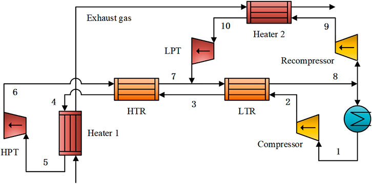
FIGURE 8. A modified recompression sCO2 cycle for engine waste heat recovery (adapted from (Zhang et al., 2020b)).
Concentrated Solor Power System
The performance of sCO2 cycles has been investigated for high-temperature solar thermal power systems. The thermal efficiency was approximately 32% with a source temperature of 600°C and a compressor inlet pressure of 85 bar (Garg et al., 2013). Al-Sulaiman and Atif (Al-Sulaiman and Atif, 2015) evaluated five different configurations of sCO2 cycles for a solar power plant with a heliostat field. The highest thermal efficiency was obtained by the recompression cycle with an integrated system efficiency of 40%. The regenerative cycle also showed a comparable performance. Singh et al. (Singh et al., 2013) analyzed the dynamic performance of a direct-heated regenerative sCO2 cycle for large-scale solar power generation. In summer, the compressor inlet pressure increases owing to the abundant solar radiation, leading to a decrease in the net power output. In winter, CO2 might change to a subcritical state at the outlet of the cooler owing to low ambient temperature. Active control is required to ensure optimal operation of the system during all seasons.
Solar radiation varies significantly at different times of the day. A heat storage device was installed to alleviate the influence of temperature fluctuations. Wang et al. (Wang et al., 2018c) studied a CSP system with heat storage. The recompression sCO2 cycle was integrated with reheating and intercooling. The solar circuit was coupled with the sCO2 cycle via a heat storage device. A salt mixture (8.1 wt% NaCl + 31.3 wt% KCl + 60.6 wt% ZnCl2) was used in the heat storage device to balance the energy fluctuations of the heat addition process. Based on the radiation data of a typical sunny day in western China, the total photoelectric efficiency could reach 19.17–22.03%, which was higher than that of traditional tower solar systems.
When the power output fluctuates frequently, the performances of the turbine and compressor degrade significantly and may even cause the failure of the control strategy. For every 1% reduction in the turbine efficiency, the system efficiency and relative power output could be decreased by 0.431 and 1.713%, respectively (Son et al., 2020). Therefore, to improve the robustness of the sCO2 cycle, the variations in the efficiencies of the turbine and compressor should be fully evaluated during the system design stage, rather than assuming a constant efficiency (Wang et al., 2020). The turbine power output of a commercial sCO2 system may be greater than 10 MW (Sienicki et al., 2011). For a large-scale system, a multi-stage axial-flow turbine can be used with high efficiency. Because of the variability of solar radiation, the operation characteristics of the CSP system under transient processes need to be verified to ensure that the entire system can operate continuously. An indirect sCO2 system with a heat storage device is more suitable and can maintain a stable system power output.
A radial turbine can be used in a sCO2 cycle owing to its low expansion ratio. El Samad et al. (El Samad et al., 2020) designed a single-stage radial turbine for a 100 MW sCO2 cycle. A total pressure of 29.7 MPa and a temperature of 1173 K were specified at the turbine inlet. The expansion ratio was 4.95, with a mass flow rate of 354.2 kg/s. The total-to-static efficiency exceeded 83%. For CO2 turbines, the bearing is an important part. Du et al. (Du et al., 2020b) designed an effective dry gas sealing structure. Compared with the conventional shroud or labyrinth design, the leakage loss was reduced, and the aerodynamic performance was improved. A special hybrid hydrostatically assisted hydrodynamic gas foil bearing is also a good option. However, the upper limit of the allowable temperature with a coating is 650°C, which limits its applicability. Another option is the rare-earth element magnetic bearing.
Large-scale high-temperature solar thermal power systems are generally built in desert areas where solar radiation is abundant and air cooling is required (Monjurul Ehsan et al., 2020). Air cooling is feasible for sCO2 cycles in CSP applications. A good temperature match inside the cooler is realized, and the exergy loss is reduced. A comparison between the steam Rankine cycle and the sCO2 cycle for power generation from solar energy indicated that the net thermal efficiency of the sCO2 cycle was 32.9%, while it was 28.2% for the steam Rankine cycle (Shrivastava and Prabu, 2016).
Geothermal Power Generation
Geothermal sources have a much lower temperature than nuclear reactors and coal-fired power plants. Generally, the tCO2 Rankine cycle is more suitable for low-grade energies. A relatively low condensation temperature is required to ensure the operation of a tCO2 power system. However, it may be difficult to condense CO2 if the ambient temperature is high. Few investigations have evaluated the feasibility of the sCO2 cycle for the utilization of geothermal energy. Ruiz-Casanova et al. (Ruiz-Casanova et al., 2020) compared four different configurations and reported that intercooling could reduce the mass flow of CO2 and thus decline the compression work. Regeneration slightly increased the mass flow rate of CO2, resulting in an increase in the power output. Among the four configurations, the performance of the regenerative sCO2 cycle with intercooling was the best, with optimal thermal and exergy efficiencies of 11.51% and 52.49%, respectively.
For high-temperature applications, special attention should be paid to the corrosivity of CO2 and impurities in the system materials. Some materials can form a protective oxide film on the surface, such as chromium oxide and alumina, and have good compatibility with CO2. Haynes 230 (Haynes International, 2007) or 617 alloy (Li et al., 2008) can be used for high thermal fatigue resistance.
Several MW-level CO2 experimental systems, which concentrated on simple and recuperated configurations, have been built. More experimental systems need to be developed to validate the theoretical results. Furthermore, during the development of experimental system, technical issues can be discovered, and expertise can be gained aiding future engineering development.
Compared with the conventional steam Rankine cycle, the sCO2 cycle has low critical pressure, high density, high heat transfer rate, high specific power, and small size (Feng and Wang, 2019), thereby making it suitable for various heat sources. In this section, recent advancements in the sCO2 cycle in the applications of nuclear reactors, coal-fired power plants, waste heat recovery, CSP systems, and geothermal power plants are presented. Table 8 shows the operating conditions of the sCO2 cycles for these applications, and the corresponding advantages and disadvantages are listed.
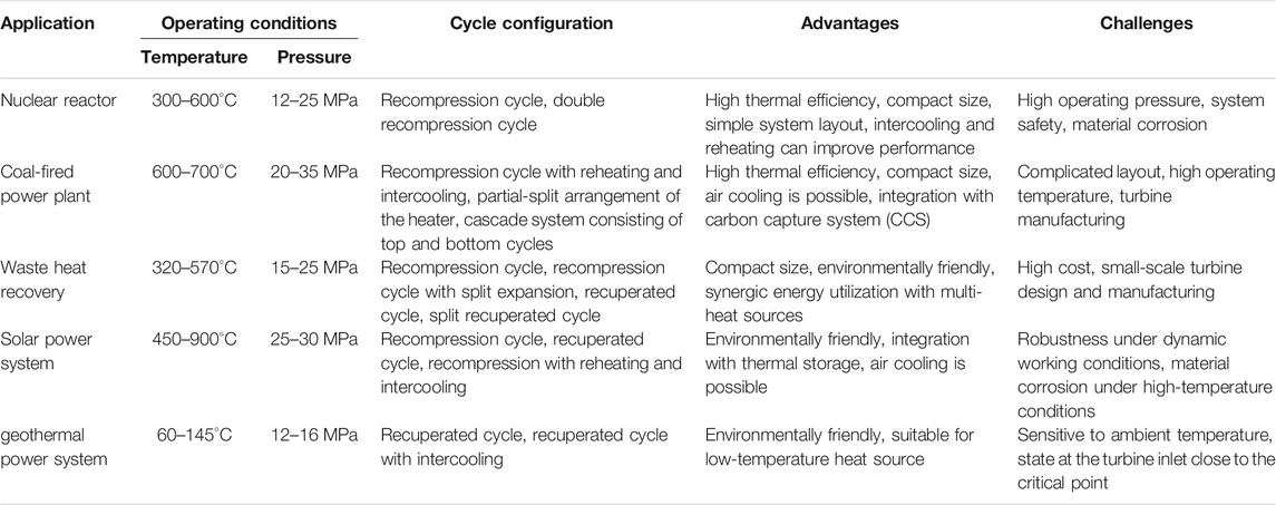
TABLE 8. Characteristics of sCO2 cycles for different applications.
Applications of tCO2 Rankine Cycles
A tCO2 cycle is suitable for low-grade energy utilization if the ambient temperature is lower than 30°C, such as in low-temperature geothermal and solar power generation. Compared with an ORC, a tCO2 cycle takes advantage of its environmentally friendly properties and compact size. The configurations of the tCO2 cycle for low-temperature heat sources are limited, with most focusing on the simple or recuperated cycle. Compared with the working fluids of ethane, toluene, siloxane D4, and water, the exergy efficiency of a simple or regenerative tCO2 cycle is greater, and the system size is smaller; however, the thermal efficiency is lower (Cardemil and da Silva, 2016). The recuperated tCO2 cycle can improve the thermal efficiency and net power output and reduce the maximum pressure of the system in comparison to the simple tCO2 cycle (Wu et al., 2018). Additionally, the performance degradation of the recuperated cycle under off-design conditions is lower.
Water cooling is favorable for most applications. The temperature of the geothermal water at the evaporator outlet is generally constrained to over 70°C to prevent the precipitation of silica from geothermal water. Owing to this constraint, the CO2 flow rate decreases gradually with the reduction in cooling water temperature, and the net power output increases at first and then decreases. There is an optimal cooling water temperature that maximizes the net power output. Air cooling is also feasible in cold climate regions. If the cooling water temperature is too high, it is impossible to condense the subcritical CO2. Pan et al. (Pan et al., 2020) proposed a self-condensing tCO2 cycle. In the proposed cycle, CO2 is cooled to a saturated vapor state by cooling water and then expanded to a subcritical two-phase state through an expansion valve. Subsequently, they are separated. The system can operate steadily at a cooling water temperature as high as 30°C. Furthermore, a tCO2 cycle can be integrated with liquefied natural gas (LNG) gasification equipment, where LNG is used as the heat sink of the tCO2 cycle, and the overall system efficiency can be improved significantly (Abdollahpour et al., 2020). Another feasible method is to use a mixture containing CO2 and a small amount of another fluid with a high boiling point, such as C6F6 (Lasala et al., 2015), C6F14 (Lasala et al., 2014), or TiCl4 (Bonalumi et al., 2020). The condensation temperature is greater than the critical temperature of pure CO2. Such a system has a high potential for CSP applications in hot regions.
At present, Echogen provides commercial products of tCO2 power cycle: EPS100, EPS35, and EPS30 (Ecogen Inc (2021). Ecogen, 2021), with a net power output of 8, 1.8, and 1.5 MW, respectively. A recuperated configuration with air cooling is employed. These systems are designed for waste heat recovery with a supply temperature of 500–532°C. Compared with the conventional steam Rankine cycle, the tCO2 system has a smaller size and lower cost of electricity. The small-scale tCO2 cycle is still in the development stage. Ge et al. (Ge et al., 2018) developed a 5 kW experimental recuperated tCO2 cycle. A single-stage axial-flow turbine with a reactivity of 0.5, and an expansion ratio of 1.5 was used. A radial turbine is more suitable for a small-scale tCO2 cycle than an axial turbine. When the system operates under dynamic conditions, a suitable control strategy is required to adjust the operation parameters. Generally, the optimal pressure control method with an adjustable nozzle blade is slightly better than the conventional pressure sliding method with a fixed nozzle (Du et al., 2018).
There are some disadvantages to tCO2 cycles, including high operating pressure, difficult condensation, and low thermal efficiency. To overcome these disadvantages, a binary mixture consisting of CO2 and an organic working fluid can be used (Shu et al., 2018). The organic working fluid has a higher critical temperature than the CO2. Thus, zeotropic mixtures containing CO2 can alleviate the condensation problem of the tCO2 cycle (Xia et al., 2020). However, the total heat transfer area of the system increases owing to the increase in the size of the condenser.
Combined Power Cycle
The CO2 power cycle is generally used alone, but it can also be combined with other cycles. Figure 9 shows the possible ways of forming a combined power system based on a sCO2 cycle. According to the principle of synthetically cascaded utilization of energy, a combined power cycle can improve the overall energy efficiency.
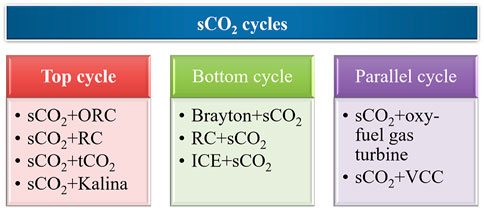
FIGURE 9. Possible approaches for the combined system based on sCO2 cycles.
A combined power system can be used for a single heat source. For example, a CO2 power cycle is cascaded with a bottoming ORC. Mondal et al. (Mondal et al., 2020) designed a combined system consisting of a tCO2 cycle and an ORC for the waste heat recovery of a marine engine. The operating pressure of the tCO2 cycle decreased, which was conducive for leakage reduction and system reliability. The results showed that it could save 8–9.5% of fuel per year. Such a combined cycle was used for waste heat recovery of a gas turbine, and the overall thermal efficiency and levelized cost of electricity reached 52.1% and 52.8 $/MWh, respectively (Mohammadi et al., 2020). Compared with the standalone CO2 power cycle, the combined system had a higher heat recovery potential and better thermoeconomic performance. For high-temperature heat sources, a sCO2 cycle can be integrated with a tCO2 cycle. Su et al. (Su et al., 2020) designed such a sCO2-tCO2 combined system for the waste heat recovery of a gas turbine. The heat sink was an LNG. The thermal and exergy efficiencies of the combined system were 52.94% and 30.27% at the design point. When a simple tCO2 cycle is employed as the bottom cycle, the expansion ratio of the turbine is lower than that of an ORC cycle, leading to better off-design performance (Wang and Dai, 2016). Additionally, a combined system integrating a sCO2 cycle with the Kalina cycle is also feasible. The sCO2 cycle is used as the top cycle. The heat rejection of the precooler in the sCO2 cycle can be transmitted to the Kalina cycle. The results showed that the exergy efficiency of the combined system could be improved by 10% (S. Mahmoudi et al., 2016).
Various types of heat sources may exist in industrial processes. A CO2 power cycle can be cascaded with an ORC or a conventional steam Rankine cycle to fully utilize these different energies. For example, a combined system of the sCO2 cycle and ORC can be designed to reclaim waste heat from engine exhaust and coolant. The topping sCO2 cycle is used to recover the waste heat of the exhaust gas, and the bottoming ORC is used to absorb the heat rejection of the sCO2 cycle, waste heat of the engine coolant, and residual heat of the exhaust gas. The maximum net power output and minimum specific investment cost of the combined system were 58% and 4% higher than those of the single sCO2 power cycle (Song et al., 2020). Combined systems have broad potential for engine waste heat recovery and other similar industrial applications.
A CO2 power cycle can be integrated with other power systems in parallel to form a complex synthetic energy system. For example, a sCO2 cycle was designed for a waste incineration power plant by Hao et al. (Chen et al., 2020). The sCO2 cycle was operated together with a coal-fired steam Rankine cycle in parallel. Compared with the separated sCO2 power system, the waste-to-electricity efficiency was enhanced by 8.34%. Economic analysis showed that the payback period was reduced by 4.2 years. Meanwhile, the net present value of the waste power generation project was increased by 18.17 M$. Compressed air energy storage systems are used to solve the problem of solar energy discontinuity and improve the flexibility of solar energy utilization. Meng et al. (Meng et al., 2020) designed a solar tCO2 cycle to recover the waste energy of high-temperature compressed air, and the energy efficiency was evidently improved.
Toshiba proposed a tCO2 cycle combined with an oxy-fuel gas turbine, called the Allam cycle (Iwai et al., 2015; Allam et al., 2017; Suzuki et al., 2019). CO2 was used as the working fluid and heated in the combustor during combustion. Oxy-fuel and oxygen were delivered to the combustor, and the products were steam and CO2. A turbine inlet pressure of 31 MPa and inlet temperature of 727°C were obtained. Subsequently, the burned gases were expanded, and a separator was installed to separate the water. Gaseous CO2 was condensed to a liquid state, and the redundant CO2 was extracted after pressurization. In 2016, a 50 MWe demo system was built, and a 300 MWe system fueled with natural gas was planned. Compared with conventional power plants with carbon capture, a net efficiency of 59% for natural gas and 51% for coal can be achieved by the Allam cycle. In addition, nearly 100% of CO2 can be captured with low projected capital and O&M costs.
Economic Analysis of CO2 Cycle
Economic performance is an important factor affecting decision-making. The conventional model based on chemical engineering plant cost index (CEPCI) is generally employed to estimate the capital cost (Turton et al., 2009; Kwon et al., 2016). Liu et al. (Liu et al., 2018) analyzed the economic performance of a sCO2 cycle recovering the flue gas heat of a 600 MW coal-fired power plant. The sCO2 cycle could reduce energy consumption compared with the traditional economizer method. The payback period of the system was 3.067 years, and the net present value could reach 16.132 million US dollars with a service life of 20 years, manifesting good economic performance. Cayer (Cayer et al., 2009) estimated the performance of a tCO2 cycle for industrial waste gas at a temperature of 100°C and a flow rate of 314.5 kg/s. The results showed that the regenerator was conducive to reducing the maximum working pressure of the system. However, the UA value of the regenerative cycle was larger than that of the simple cycle. Wang et al. (Wang et al., 2018c) compared the performances of three tCO2 cycles. The single-stage tCO2 cycle had a good economic performance over the entire temperature range of the heat source. The two-stage cycle had a better economic performance only when the heat source temperature was higher than 530°C, and a multi-objective optimization algorithm was required if both the thermodynamic and economic performances were to be considered simultaneously. Li et al. (Li et al., 2018) established an economic model for a tCO2 cycle based on the NSGA-II algorithm. The optimized system thermal and exergy efficiencies were 8.51% and 29.59%, respectively.
Generally, CO2 power cycles have a higher cost than ORCs, which is the main factor restricting commercial production. Using zeotropic mixtures containing CO2 is a feasible option that can reduce costs while maintaining high efficiency (Xia et al., 2018). At present, few investigations have focused on the economic performance of CO2 power cycles. More efforts are required for various industrial applications to provide a comprehensive comparison among the conventional steam Rankine cycle, ORC, Kalina, and other power systems.
Technical Challenges and Possibilities of Future Development
Although CO2 power cycles have great potential for industrial applications, some technical challenges still need to be overcome. Figure 10 shows the main challenges and possible directions for future development. First, CO2 is a natural working fluid with environmentally friendly characteristics, such as zero ODP and low GWP. However, CO2 is a limiting substance in the occupational exposure limit standard for hazardous factors in the workplace. CO2 with a concentration greater than 2% will cause fatal harm to human beings in a closed space. Generally, the concentration of CO2 prescribed in the hygiene requirements is less than 5000 ppm. Therefore, CO2 gas leakage detection and the formulation of relevant safety specifications are needed to provide safety support for the industrial application of CO2 power cycles.
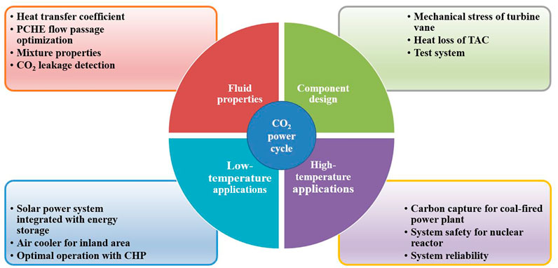
FIGURE 10. Technical challenges and possible future developments of CO2 power cycles.
The characteristics of fluid flow and heat transfer of supercritical CO2 need to be investigated experimentally such that accurate correlations can be developed for a wide range of CO2 power cycles. PCHEs that can operate under high-pressure and temperature conditions are suitable for applications with a compact size requirement. Flow passage optimization and reduction of pressure drops of PCHEs should be investigated further. Furthermore, CO2 can be used as a flame retardant and blended with an organic working fluid. The thermophysical properties of zeotropic mixtures containing CO2 should be measured to provide accurate data for industrial applications. Thus, a high-fidelity economic model and a comprehensive analysis can be performed.
The energy efficiency of the high-temperature sCO2 power cycle increases with an increase in the maximum working pressure. However, the high operating temperature poses a severe challenge to metal materials. The material strength should be improved, and the wall thickness must be increased. In addition, it is possible to control the maximum working pressure to a reasonable level and improve the system efficiency by reducing the exergy loss of the components. For coal-fired power plants, the design of a high-temperature sCO2 power cycle needs to be considered together with the design of carbon capture and carbon storage devices to meet the carbon neutrality target.
CO2 power cycles take advantages of environmentally friendly properties, low cost, high output power, and are best suited for solar and geothermal sources. For solar power applications, a solar collector with high concentrating performance can enhance the operating temperature and system efficiency. Combining it with a heat storage device can effectively suppress fluctuations in solar energy. Furthermore, it can be integrated with domestic heat supply such that comprehensive energy utilization is realized, and the energy efficiency is improved greatly. This has good prospects in micro-distributed energy supply systems. For low-temperature geothermal power generation, few investigations have focused on the CO2 power system, and more research and engineering developments are needed. A supercritical state is observed for the sCO2 cycle during the cooling process, and air cooling is feasible, especially for areas with water shortages. A tCO2 cycle is more suitable for areas at high latitudes or altitudes with low ambient temperatures or areas with abundant water resources.
The high-pressure and high-temperature operating conditions of CO2 power systems are a severe challenge to the reliability and durability of the system components, which require careful verification in engineering practice. Supercritical CO2 with high density has a significant impact on the high-speed rotating vanes of the turbine and compressor, and the mechanical stress of the blades must be specified in the design. To ensure reliable sealing and improve the compactness of the system, the compressor, alternator, and turbine are designed as an integrated turbine-alternator-compressor (TAC). Generally, high heat loss occurs owing to the heat transfer between the different parts of the TAC. It is necessary to reduce the heat loss of the turbine to a very low level while simultaneously ensuring good cooling of the alternator. The optimal regulation of the compressor and turbine under off-design conditions needs to be further studied.
Conclusion
In this paper, recent advancements in the system design and applications of supercritical/transcritical CO2 power cycles are discussed. Single-flow and split-flow CO2 power cycles have their own advantages. New CO2 power cycles can be designed by enhancing the processes of heating, recuperation, compression, and expansion. For a high-temperature heat source with a large specific heat capacity, the recompression configuration is suitable owing to its high efficiency and relatively simple structure. The split expansion configuration with reheating and intercooling is more suitable for heat sources with a small specific heat capacity. In addition, the CO2 power system combining the single-flow and split-flow cycles may provide a method to improve energy efficiency further, and fully utilize the advantages of both configurations. Furthermore, novel systems may be designed by combining the sCO2 cycle with the tCO2 cycle if the ambient temperature is low. The CO2 power cycle can also be integrated with refrigeration and heating devices to realize the comprehensive utilization of energy, which is of great significance for applications such as distributed energy systems.
Different sCO2 Brayton cycles have been investigated extensively for nuclear reactors, coal-fired plants, CSP, and high-temperature waste heat recovery. However, few investigations have focused on tCO2 cycles. More efforts are required to evaluate the feasibility and potential of different tCO2 Rankine cycles for low-grade heat sources, especially for small-scale applications. In practice, a comprehensive analysis of the CO2 power cycle, including an evaluation of its economic performance, is required. To accelerate the industrial application of CO2 power cycles, more efforts should be devoted to engineering activities, including component manufacturing, system seal, reliability and durability, system control, and optimization, in the future.
Author Contributions
EW contributes to conceptualization, literature survey, paper drafting, and funding acquisition. NP is mainly responsible for the data curation and writing paper. MZ contributes to the paper modification, resources, visualization.
Funding
This research work was supported by the National Natural Science Foundation of China (Grant No. 51876009).
Conflict of Interest
The authors declare that the research was conducted in the absence of any commercial or financial relationships that could be construed as a potential conflict of interest.
Publisher’s Note
All claims expressed in this article are solely those of the authors and do not necessarily represent those of their affiliated organizations, or those of the publisher, the editors and the reviewers. Any product that may be evaluated in this article, or claim that may be made by its manufacturer, is not guaranteed or endorsed by the publisher.
Abbreviations
CEPCI, chemical engineering plant cost index; CFC, chlorofluorocarbon; CHP, combine heat and power; CSP, concentrated solar power; GWP, global warming potential; HPT, high-pressure turbine; HTR, high-temperature recuperator; ICE, internal combustion engine; LNG, liquefied natural gas; LPT, low-pressure turbine; LTR, low-temperature recuperator; ODP, ozone depletion potential; ORC, organic Rankine cycle; PCHE, printed circuit heat exchanger; RC, Rankine cycle; sCO2, supercritical CO2 power cycle; TAC, turbine-alternator-compressor; tCO2, transcritical CO2 power cycle; VCC, vapor compression cycle.
References
Abdollahpour, A., Ghasempour, R., Kasaeian, A., and Ahmadi, M. H. (2020). Exergoeconomic Analysis and Optimization of a Transcritical CO2 Power Cycle Driven by Solar Energy Based on Nanofluid with Liquefied Natural Gas as its Heat Sink. J. Therm. Anal. Calorim. 139, 451–473. doi:10.1007/s10973-019-08375-6
Ahn, Y., Bae, S. J., Kim, M., Cho, S. K., Baik, S., Lee, J. I., et al. (2015). Review of Supercritical CO2 Power Cycle Technology and Current Status of Research and Development. Nucl. Eng. Tech. 47, 647–661. doi:10.1016/j.net.2015.06.009
Al-Sulaiman, F. A., and Atif, M. (2015). Performance Comparison of Different Supercritical Carbon Dioxide Brayton Cycles Integrated with a Solar Power Tower. Energy 82, 61–71. doi:10.1016/j.energy.2014.12.070
Allam, R., Martin, S., Forrest, B., Fetvedt, J., Lu, X., Freed, D., et al. (2017). Demonstration of the Allam Cycle: An Update on the Development Status of a High Efficiency Supercritical Carbon Dioxide Power Process Employing Full Carbon Capture. Energ. Proced. 114, 5948–5966. doi:10.1016/j.egypro.2017.03.1731
Angelino, G. (1968). Carbon Dioxide Condensation Cycles for Power Production. J. Eng. P 90, 287–295. doi:10.1115/1.3609190
Aungier, R. H. (2006). Turbine Aerodynamics–Axial Flow and Radial-inflow Turbine Design and Analysis. New York, NY: ASME.
Ayub, A., Sheikh, N. A., Tariq, R., Khan, M. M., and Invernizzi, C. M. (2018). Exergetic Optimization and Comparison of Combined Gas Turbine Supercritical CO2 Power Cycles. J. Renew. Sust. Energ. 10, 044703. doi:10.1063/1.5038333
Bae, S. J., Lee, J., Ahn, Y., and Lee, J. I. (2015). Preliminary Studies of Compact Brayton Cycle Performance for Small Modular High Temperature Gas-cooled Reactor System. Ann. Nucl. Energ. 75, 11–19. doi:10.1016/j.anucene.2014.07.041
Bonalumi, D., Lasala, S., and Macchi, E. (2020). CO2-TiCl4 Working Fluid for High-temperature Heat Source Power Cycles and Solar Application. Renew. Energ. 147, 2842–2854. doi:10.1016/j.renene.2018.10.018
Cardemil, J. M., and da Silva, A. K. (2016). Parametrized Overview of CO2 Power Cycles for Different Operation Conditions and Configurations - An Absolute and Relative Performance Analysis. Appl. Therm. Eng. 100, 146–154. doi:10.1016/j.applthermaleng.2015.11.084
Carstens, N. A., Hejzlar, P., and Driscoll, M. J. (2006). Control System Strategies and Dynamic Response for Supercritical CO2 Power Conversion Cycles. Tech. Rep. MIT-ANP-TR. (Cambridge, Massachusetts: MIT Nuclear Engineering Department), 038.
Cavallini, A., and Zecchin, R. (1974). “A Dimensionless Correlation for Heat Transfer in Forced Convection Condensation,” in The Proceedings of the Fifth International Heat Transfer Conference, Tokyo, Japan, September, 3-7. doi:10.1615/ihtc5.1220
Cayer, E., Galanis, N., Desilets, M., Nesreddine, H., and Roy, P. (2009). Analysis of a Carbon Dioxide Transcritical Power cycle Using a Low Temperature Source. Appl. Energ. 86, 1055–1063. doi:10.1016/j.apenergy.2008.09.018
Cayer, E., Galanis, N., and Nesreddine, H. (2010). Parametric Study and Optimization of a Transcritical Power Cycle Using a Low Temperature Source. Appl. Energ. 87, 1349–1357. doi:10.1016/j.apenergy.2009.08.031
Cha, J.-E., Lee, T.-H., Eoh, J.-H., Seong, S.-H., Kim, S.-O., Kim, D.-E., et al. (2009). Development of a Supercritical CO2 Brayton Energy Conversion System Coupled with a Sodium Cooled Fast Reactor. Nucl. Eng. Tech. 41, 1025–1044. doi:10.5516/net.2009.41.8.1025
Chen, H., Zhang, M., Wu, Y., Xu, G., Liu, W., and Liu, T. (2020). Design and Performance Evaluation of a New Waste Incineration Power System Integrated with a Supercritical CO2 Power Cycle and a Coal-fired Power Plant. Energ. Convers. Manag. 210, 112715. doi:10.1016/j.enconman.2020.112715
Chen, Y., Lundqvist, P., and Platell, P. (2005). Theoretical Research of Carbon Dioxide Power Cycle Application in Automobile Industry to Reduce Vehicle's Fuel Consumption. Appl. Therm. Eng. 25, 2041–2053. doi:10.1016/j.applthermaleng.2005.02.001
Cho, S. K., Kim, M., Baik, S., Ahn, Y., and Lee, J. I. (2015). Investigation of the Bottoming Cycle for High Efficiency Combined Cycle Gas Turbine System with Supercritical Carbon Dioxide Power Cycle. ASME Turbo Expo. 2015 Turbine Tech. Conf. Exposition, V009T36A011. doi:10.1115/gt2015-43077
Chys, M., van den Broek, M., Vanslambrouck, B., and De Paepe, M. (2012). Potential of Zeotropic Mixtures as Working Fluids in Organic Rankine Cycles. Energy 44, 623–632. doi:10.1016/j.energy.2012.05.030
Cooke, D. H. (1984). On Prediction of Off-design Multistage Turbine Pressures by Stodola's Ellipse. J. Eng. Gas Turbines Power 107, 596–606. doi:10.1115/84-jpgc-gt-14
Crespi, F., Gavagnin, G., Sánchez, D., and Martínez, G. S. (2017). Supercritical Carbon Dioxide Cycles for Power Generation: A Review. Appl. Energ. 195, 152–183. doi:10.1016/j.apenergy.2017.02.048
Dostal, V., Driscoll, M. J., and Hejzlar, P. (2004). A Supercritical Carbon Dioxide Cycle for Next Generation Nuclear Reactors. Tech. Rep. MIT-ANP-TR. (Cambridge, Massachusetts: MIT Nuclear Engineering Department), 100.
Du, Q., Zhang, L., Zhang, D., and Xie, Y. (2020). Numerical Investigation on Flow Characteristics and Aerodynamic Performance of Shroud Seal in a Supercritical CO2 Axial-flow Turbine. Appl. Therm. Eng. 169, 114960. doi:10.1016/j.applthermaleng.2020.114960
Du, X., Hu, J., and Xia, G. (2020). Operation Characteristic of Supercritical Carbon Dioxide-cooled Reactor System Under Coordination Control Scheme. Int. J. Adv. Robot Syst. 17, 1–13. doi:10.1177/1729881420933833
Du, Y., Chen, H., Hao, M., Qiang, X., Wang, J., and Dai, Y. (2018). Off-design Performance Comparative Analysis of a Transcritical CO2 Power Cycle Using a Radial Turbine by Different Operation Methods. Energ. Convers. Manag. 168, 529–544. doi:10.1016/j.enconman.2018.05.036
Ehsan, M. M., Guan, Z., Gurgenci, H., and Klimenko, A. (2020). Feasibility of Dry Cooling in Supercritical CO2 Power Cycle in Concentrated Solar Power Application: Review and a Case Study. Renew. Sust Energ Rev. 132, 110055. doi:10.1016/j.rser.2020.110055
El Samad, T., Amaral Teixeira, J., and Oakey, J. (2020). Investigation of a Radial Turbine Design for a Utility-Scale Supercritical CO2 Power Cycle. Appl. Sci. 10, 4168. doi:10.3390/app10124168
Ely, J. F., Magee, J. W., and Haynes, W. M. (1987). Thermophysical Properties for Special High CO2 Content Mixtures Research Report RR-110. Tulsa, OK: Gas Processors Association.
Feng, Y., and Wang, J. (2019). Review of Supercritical Carbon Dioxide Brayton Cycle Research. Energy and Energy Conservation (2), 91–100. doi:10.16643/j.cnki.14-1360/td.2019.02.044
Floyd, J., Alpy, N., Moisseytsev, A., Haubensack, D., Rodriguez, G., Sienicki, J., et al. (2013). A Numerical Investigation of the sCO2 Recompression Cycle Off-design Behaviour, Coupled to a Sodium Cooled Fast Reactor, for Seasonal Variation in the Heat Sink Temperature. Nucl. Eng. Des. 260, 78–92. doi:10.1016/j.nucengdes.2013.03.024
Garg, P., Kumar, P., and Srinivasan, K. (2013). Supercritical Carbon Dioxide Brayton Cycle for Concentrated Solar Power. J. Supercrit. Fluids 76, 54–60. doi:10.1016/j.supflu.2013.01.010
Ge, Y. T., Li, L., Luo, X., and Tassou, S. A. (2018). Performance Evaluation of a Low-grade Power Generation System with CO2 Transcritical Power Cycles. Appl. Energ. 227, 220–230. doi:10.1016/j.apenergy.2017.07.086
Guo, Z., Zhao, Y., Zhu, Y., Niu, F., and Lu, D. (2018). Optimal Design of Supercritical CO2 Power Cycle for Next Generation Nuclear Power Conversion Systems. Prog. Nucl. Energ. 108, 111–121. doi:10.1016/j.pnucene.2018.04.023
Halimi, B., and Suh, K. Y. (2012). Computational Analysis of Supercritical CO2 Brayton Cycle Power Conversion System for Fusion Reactor. Energ. Convers. Manag. 63, 38–43. doi:10.1016/j.enconman.2012.01.028
Ham, J., Kim, M., Oh, B., Son, S., Lee, J., and Lee, J. (2019). A Supercritical CO2 Waste Heat Recovery System Design for a Diesel Generator for Nuclear Power Plant Application. Appl. Sci. 9, 5382. doi:10.3390/app9245382
Hou, S., Zhou, Y., Yu, L., Zhang, F., Cao, S., and Wu, Y. (2018). Optimization of a Novel Cogeneration System Including a Gas Turbine, a Supercritical CO2 Recompression Cycle, a Steam Power Cycle and an Organic Rankine Cycle. Energ. Convers. Manag. 172, 457–471. doi:10.1016/j.enconman.2018.07.042
Huang, X., Wang, J., and Zang, J. (2016). Thermodynamic Analysis of Coupling Supercritical Carbon Dioxide Brayton Cycles. Nucl. Power Eng. 37, 34–38. doi:10.13832/j.jnpe.2016.03.0034
Iwai, Y., Itoh, M., Morisawa, Y., Suzuki, S., Cusano, D., and Harris, M. (2015). “Development Approach to the Combustor of Gas Turbine for Oxyfuel, Supercritical CO2 Cycle,” in Proceedings of the ASME Turbo Expo 2015 Turbine Technical Conference and Exposition, Montreal, Canada, June 15–19, 2015.
Kedzierski, M. A., and Goncalves, J. M. (1999). Horizontal Convective Condensation of Alternative Refrigerants Within a Micro-fin Tube. J. Enh Heat Transf 6, 161–178. doi:10.1615/jenhheattransf.v6.i2-4.90
Kim, M., Pettersen, J., and Bullard, C. W. (2004). Fundamental Process and System Design Issues in CO2 Vapor Compression Systems. Prog. Energ. Combustion Sci. 30, 119–174. doi:10.1016/j.pecs.2003.09.002
Kim, M. S., Ahn, Y., Kim, B., and Lee, J. I. (2016). Study on the Supercritical CO2 Power Cycles for Landfill Gas Firing Gas Turbine Bottoming Cycle. Energy 111, 893–909. doi:10.1016/j.energy.2016.06.014
Kumar, P., and Srinivasan, K. (2016). Carbon Dioxide Based Power Generation in Renewable Energy Systems. Appl. Therm. Eng. 109, 831–840. doi:10.1016/j.applthermaleng.2016.06.082
Kunz, O., Klimeck, R., Wagner, W., and Jaeschke, M. (2007). “The GERG-2004 Wide-range Equation of State for Natural Gases and Other Mixtures,” in GERG Technical Monograph 15, Fortschritt-Berichte VDI (Dusseldorf: VDI-Verlag).
Kwon, J. G., Kim, T. H., Park, H. S., Cha, J. E., and Kim, M. H. (2016). Optimization of Airfoil-type PCHE for the Recuperator of Small Scale Brayton Cycle by Cost-based Objective Function. Nucl. Eng. Des. 298, 192–200. doi:10.1016/j.nucengdes.2015.12.012
Lasala, S., Chiesa, P., and Macchi, E. (2014). “Binary Mixtures of Carbon Dioxide and Fluorocarbons as Working Fluids for Power Production Applications,” in JEEP 2014 Conference. Lyon, France: JEEP, 26–28.
Lasala, S., Invernizzi, C., Iora, P., Chiesa, P., and Macchi, E. (2015). Thermal Stability Analysis of Perfluorohexane. Energ. Proced. 75, 1575–1582. doi:10.1016/j.egypro.2015.07.358
Lee, J. I., and Sanchez, D. (2020). Recent Advancement of Thermal Fluid Engineering in the Supercritical CO2 Power Cycle. Appl. Sci. 10, 5350. doi:10.3390/app10155350
Lee, J., Lee, J., Ahn, Y., and Yoon, H. (2012). “Design Methodology of Supercritical CO2 Brayton Cycle Turbomachineries,” in Proceedings of ASME Turbo Expo 2012 Turbine Technical Conference and Exposition (Denmark: Copenhagen).
Lee, S., and Gurgenci, H. (2020). A Comparison of Three Methodological Approaches for Meanline Design of Supercritical CO2 Radial Inflow Turbines. Energ. Convers. Manag. 206, 112500. doi:10.1016/j.enconman.2020.112500
Li, H., Yang, Y., Cheng, Z., Sang, Y., and Dai, Y. (2018). Study on Off-design Performance of Transcritical CO2 Power Cycle for the Utilization of Geothermal Energy. Geothermics 71, 369–379. doi:10.1016/j.geothermics.2017.09.002
Li, X., Kininmont, D., Le Pierres, R., and Dewson, S. J. (2008). “Alloy 617 for the High Temperature Diffusion-bonded Compact Heat Exchangers,” in Proceedings of ICAPP (Anaheim, CA: ICAPP).
Li, Z., Liu, X., Shao, Y., and Zhong, W. (2020). Research and Development of Supercritical Carbon Dioxide Coal-fired Power Systems. J. Therm. Sci. 29, 546–575. doi:10.1007/s11630-020-1282-6
Liu, M., Zhang, X., Ma, Y., and Yan, J. (2018). Thermo-economic Analyses on a New Conceptual System of Waste Heat Recovery Integrated with an sCO2 Cycle for Coal-fired Power Plants. Energ. Convers. Manag. 161, 243–253. doi:10.1016/j.enconman.2018.01.049
Liu, Y., Wang, Y., and Huang, D. (2019). Supercritical CO2 Brayton Cycle: A State-of-the-art Review. Energy 189, 115900. doi:10.1016/j.energy.2019.115900
Liu, Y., Zhao, Y., Yang, Q., Liu, G., and Li, L. (2020). Thermodynamic Comparison of CO2 Power Cycles and their Compression Processes. Case Stud. Therm. Eng. 21, 100712. doi:10.1016/j.csite.2020.100712
Manente, G., and Costa, M. (2020). On the Conceptual Design of Novel Supercritical CO2 Power Cycles for Waste Heat Recovery. Energies 13, 370. doi:10.3390/en13020370
Manjunath, K., Sharma, O. P., Tyagi, S. K., and Kaushik, S. C. (2018). Thermodynamic Analysis of a Supercritical/transcritical CO2 Based Waste Heat Recovery Cycle for Shipboard Power and Cooling Applications. Energ. Convers. Manag. 155, 262–275. doi:10.1016/j.enconman.2017.10.097
Meng, F., Wang, E., Zhang, B., Zhang, F., and Zhao, C. (2019). Thermo-economic Analysis of Transcritical CO2 Power Cycle and Comparison with Kalina Cycle and ORC for a Low-temperature Heat Source. Energ. Convers. Manag. 195, 1295–1308. doi:10.1016/j.enconman.2019.05.091
Meng, J., Wei, M., Song, P., Tian, R., Hao, L., and Zheng, S. (2020). Performance Evaluation of a Solar Transcritical Carbon Dioxide Rankine Cycle Integrated with Compressed Air Energy Storage. Energ. Convers. Manag. 215, 112931. doi:10.1016/j.enconman.2020.112931
Modi, A., Andreasen, J. G., Kærn, M. R., and Haglind, F. (2015). Part-load Performance of a High Temperature Kalina Cycle. Energ. Convers. Manag. 105, 453–461. doi:10.1016/j.enconman.2015.08.006
Mohammadi, K., Ellingwood, K., and Powell, K. (2020). A Novel Triple Power Cycle Featuring a Gas Turbine Cycle with Supercritical Carbon Dioxide and Organic Rankine Cycles: Thermoeconomic Analysis and Optimization. Energ. Convers. Manag. 220, 113123. doi:10.1016/j.enconman.2020.113123
Moisseytsev, A., and Sienicki, J. J. (2009). Investigation of Alternative Layouts for the Supercritical Carbon Dioxide Brayton Cycle for a Sodium-cooled Fast Reactor. Nucl. Eng. Des. 239, 1362–1371. doi:10.1016/j.nucengdes.2009.03.017
Mondal, S., Datta, S., and De, S. (2020). Auxiliary Power Through Marine Waste Heat Recovery Using a CO2-organic Cascading Cycle. Clean. Techn Environ. Pol. 22, 893–906. doi:10.1007/s10098-020-01831-0
Monjurul Ehsan, M., Duniam, S., Li, J., Guan, Z., Gurgenci, H., and Klimenko, A. (2020). A Comprehensive Thermal Assessment of Dry Cooled Supercritical CO2 Power Cycles. Appl. Therm. Eng. 166, 114645. doi:10.1016/j.applthermaleng.2019.114645
Moustapha, H., Zelesky, M. F., Baines, N. C., and Japikse, D. (2003). Axial and Radial Turbines. White River Junction, VT: Concepts NREC.
Nikolai, P., Rabiyat, B., Aslan, A., and Ilmutdin, A. (2019). Supercritical CO2: Properties and Technological Applications - A Review. J. Therm. Sci. 28, 394–430. doi:10.1007/s11630-019-1118-4
Olumayegun, O., Wang, M., and Oko, E. (2019). Thermodynamic Performance Evaluation of Supercritical CO2 Closed Brayton Cycles for Coal-fired Power Generation with Solvent-based CO2 Capture. Energy 166, 1074–1088. doi:10.1016/j.energy.2018.10.127
Pan, L., Shi, W., Wei, X., Li, T., and Li, B. (2020). Experimental Verification of the Self-condensing CO2 Transcritical Power Cycle. Energy 198, 117335. doi:10.1016/j.energy.2020.117335
Peng, N., Wang, E., and Meng, F. (2020). Off-design Performance Comparison of Single-stage Axial Turbines Using CO2 and Zeotropic Mixture for Low-temperature Heat Source. Energ. Convers. Manag. 213, 112838. doi:10.1016/j.enconman.2020.112838
Petukhov, B. S. (1970). Heat Transfer and Friction in Turbulent Pipe Flow with Variable Physical Properties. in Adv. Heat Transfer, 503–564. doi:10.1016/s0065-2717(08)70153-9
Petukhov, B. S., Krasnoshchekov, E. A., and Protopopov, V. S. (1961). An Investigation of Heat Transfer to Fluids Flowing in Pipes Under Supercritical Conditions. Int. Dev. Heat Transfer 3, 569–578.
Reznicek, E. P., Hinze, J. F., Rapp, L. M., Nellis, G. F., Anderson, M. H., and Braun, R. J. (2020). One-dimensional, Transient Modeling of a Fixed-bed Regenerator as a Replacement for Recuperators in Supercritical CO2 Power Cycles. Energ. Convers. Manag. 218, 112921. doi:10.1016/j.enconman.2020.112921
Ruiz-Casanova, E., Rubio-Maya, C., Pacheco-Ibarra, J. J., Ambriz-Díaz, V. M., Romero, C. E., and Wang, X. (2020). Thermodynamic Analysis and Optimization of Supercritical Carbon Dioxide Brayton Cycles for Use with Low-grade Geothermal Heat Sources. Energ. Convers. Manag. 216, 112978. doi:10.1016/j.enconman.2020.112978
Salah, S. I., Khader, M. A., White, M. T., and Sayma, A. I. (2020). Mean-Line Design of a Supercritical CO2 Micro Axial Turbine. Appl. Sci. 10, 5069. doi:10.3390/app10155069
Sánchez, C. J. N., and da Silva, A. K. (2018). Technical and Environmental Analysis of Transcritical Rankine Cycles Operating with Numerous CO2 Mixtures. Energy 142, 180–190. doi:10.1016/j.energy.2017.09.120
Seong, S.-H., Lee, T.-H., and Kim, S.-O. (2009). Development of a Simplified Model for Analyzing the Performance of KALIMER-600 Coupled with a Supercritical Carbon Dioxide Brayton Energy Conversion Cycle. Nucl. Eng. Tech. 41, 785–796. doi:10.5516/net.2009.41.6.785
Shrivastava, A., and Prabu, V. (2016). Thermodynamic Analysis of Solar Energy Integrated Underground Coal Gasification in the Context of Cleaner Fossil Power Generation. Energ. Convers. Manag. 110, 67–77. doi:10.1016/j.enconman.2015.12.009
Shu, G., Yu, Z., Tian, H., Liu, P., and Xu, Z. (2018). Potential of the Transcritical Rankine Cycle Using CO2-based Binary Zeotropic Mixtures for Engine's Waste Heat Recovery. Energ. Convers. Manag. 174, 668–685. doi:10.1016/j.enconman.2018.08.069
Sienicki, J. J., Moisseytsev, A., Fuller, R. L., Wright, S. A., and Pickard, P. S. (2011). “Scale Dependencies of Supercritical Carbon Dioxide Brayton Cycle Technologies and the Optimal Size for a Next-step Supercritical CO2 Cycle Demonstration,” in 2011 sCO2 Power Cycle Symposium, Boulder, Colorado, May 24–25, 2011.
Singh, R., Miller, S. A., Rowlands, A. S., and Jacobs, P. A. (2013). Dynamic Characteristics of a Direct-heated Supercritical Carbon-Dioxide Brayton Cycle in a Solar Thermal Power Plant. Energy 50, 194–204. doi:10.1016/j.energy.2012.11.029
S. Mahmoudi, S., D. Akbari, A., and Rosen, M. (2016). Thermoeconomic Analysis and Optimization of a New Combined Supercritical Carbon Dioxide Recompression Brayton/Kalina Cycle. Sustainability 8, 1079. doi:10.3390/su8101079
Son, S., Baek, J. Y., Jeong, Y., and Lee, J. I. (2020). Impact of Turbomachinery Degradation on Performance and Dynamic Behavior of Supercritical CO2 Cycle. J. Eng. Gas Turbines Power-trans ASME 142, 091007. doi:10.1115/1.4047888
Song, J., Li, X. S., Ren, X. D., and Gu, C. W. (2018). Performance Improvement of a Preheating Supercritical CO2 (sCO2) Cycle Based System for Engine Waste Heat Recovery. Energ. Convers. Manag. 161, 225–233. doi:10.1016/j.enconman.2018.02.009
Song, J., Li, X., Wang, K., and Markides, C. N. (2020). Parametric Optimisation of a Combined Supercritical CO2 (S-CO2) Cycle and Organic Rankine Cycle (ORC) System for Internal Combustion Engine (ICE) Waste-heat Recovery. Energ. Convers. Manag. 218, 112999. doi:10.1016/j.enconman.2020.112999
Span, R., and Wagner, W. (1996). A New Equation of State for Carbon Dioxide Covering the Fluid Region from the Triple‐Point Temperature to 1100 K at Pressures up to 800 MPa. J. Phys. Chem. Reference Data 25 (6), 1509–1596. doi:10.1063/1.555991
Span, R., and Wagner, W. (2003). Equations of State for Technical Applications. III. Results for Polar Fluids. Int. J. Thermophys. 24 (1), 111–162. doi:10.1023/a:1022362231796
Stein, W. H., and Buck, R. (2017). Advanced Power Cycles for Concentrated Solar Power. Solar Energy 152, 91–105. doi:10.1016/j.solener.2017.04.054
Su, R., Yu, Z., Xia, L., and Sun, J. (2020). Performance Analysis and Multi-objective Optimization of an Integrated Gas turbine/supercritical CO2 Recompression/transcritial CO2 Cogeneration System Using Liquefied Natural Gas Cold Energy. Energ. Convers. Manag. 220, 113136. doi:10.1016/j.enconman.2020.113136
Sun, E., Xu, J., Li, M., Liu, G., and Zhu, B. (2018). Connected-top-bottom-cycle to Cascade Utilize Flue Gas Heat for Supercritical Carbon Dioxide Coal Fired Power Plant. Energ. Convers. Manag. 172, 138–154. doi:10.1016/j.enconman.2018.07.017
Suzuki, S., Iwai, Y., Itoh, M., Morisawa, Y., Jain, P., and Kobayashi, Y. (2019). “High Pressure Combustion Test of Gas Turbine Combustor for 50MWth Supercritical CO2 Demonstration Power Plant on Allam Cycle,” in Proceedings of the International Gas Turbine Congress (Tokyo, Japan: International Gas Turbine Congress), 17–22.
Turton, R., Bailie, R. C., and Whiting, W. B. (2009). Analysis, Synthesis, and Design of Chemical Process. New York, NY: Prentice-Hall.
Utamura, M. (2010). Thermodynamic Analysis of Part-flow Cycle Supercritical CO2 Gas Turbines. J. Eng. Gas Turbines Power 132, 111701. doi:10.1115/1.4001052
Uusitalo, A., Ameli, A., and Turunen-Saaresti, T. (2019). Thermodynamic and Turbomachinery Design Analysis of Supercritical Brayton Cycles for Exhaust Gas Heat Recovery. Energy 167, 60–79. doi:10.1016/j.energy.2018.10.181
Vesely, L., Manikantachari, K. R. V., Vasu, S., Kapat, J., Dostal, V., and Martin, S. (2019). Effect of Impurities on Compressor and Cooler in Supercritical CO2 Cycles. J. Energ Resour-asme 141, 012003. doi:10.1115/1.4040581
Wang, J., Guo, Y., Zhou, K., Xia, J., Li, Y., Zhao, P., et al. (2020). Design and performance analysis of compressor and turbine in supercritical CO2 power cycle based on system-component coupled optimization. Energy Conv Manag 221, 113179. doi:10.1016/j.enconman.2020.113179
Wang, K., He, Y.-L., and Zhu, H.-H. (2017). Integration Between Supercritical CO2 Brayton Cycles and Molten Salt Solar Power Towers: A Review and a Comprehensive Comparison of Different Cycle Layouts. Appl. Energ. 195, 819–836. doi:10.1016/j.apenergy.2017.03.099
Wang, S. S., Wu, C., and Li, J. (2018a). Exergoeconomic Analysis and Optimization of Single-pressure Single-stage and Multi-stage CO2 Transcritical Power Cycles for Engine Waste Heat Recovery: A Comparative Study. Energy 142, 559–577. doi:10.1016/j.energy.2017.10.055
Wang, X., and Dai, Y. (2016). Exergoeconomic Analysis of Utilizing the Transcritical CO2 Cycle and the ORC for a Recompression Supercritical CO2 Cycle Waste Heat Recovery: A Comparative Study. Appl. Energ. 170, 193–207. doi:10.1016/j.apenergy.2016.02.112
Wang, X., Liu, Q., Bai, Z., Lei, J., and Jin, H. (2018b). Thermodynamic Investigations of the Supercritical CO2 System with Solar Energy and Biomass. Appl. Energ. 227, 108–118. doi:10.1016/j.apenergy.2017.08.001
Wang, X., Liu, Q., Lei, J., Han, W., and Jin, H. (2018c). Investigation of Thermodynamic Performances for Two-stage Recompression Supercritical CO2 Brayton Cycle with High Temperature Thermal Energy Storage System. Energ. Convers. Manag. 165, 477–487. doi:10.1016/j.enconman.2018.03.068
White, M. T., Bianchi, G., Chai, L., Tassou, S. A., and Sayma, A. I. (2021). Review of Supercritical CO2 Technologies and Systems for Power Generation. Appl. Therm. Eng. 185, 116447. doi:10.1016/j.applthermaleng.2020.116447
Whitfield, A., and Baines, N. C. (1990). Design of Radial Turbomachines. New York, NY: Longman Scientific & Technical.
Wu, C., Wang, S. S., and Li, J. (2018). Parametric Study on the Effects of a Recuperator on the Design and Off-design Performances for a CO2 Transcritical Power Cycle for Low Temperature Geothermal Plants. Appl. Therm. Eng. 137, 644–658. doi:10.1016/j.applthermaleng.2018.04.029
Wu, P., Ma, Y., Gao, C., Liu, W., Shan, J., Huang, Y., et al. (2020). A Review of Research and Development of Supercritical Carbon Dioxide Brayton Cycle Technology in Nuclear Engineering Applications. Nucl. Eng. Des. 368, 110767. doi:10.1016/j.nucengdes.2020.110767
Xia, J., Guo, Y., Li, Y., Wang, J., Zhao, P., and Dai, Y. (2020). Thermodynamic Analysis and Comparison Study of Two Novel Combined Cooling and Power Systems with Separators Using CO2-based Mixture for Low Grade Heat Source Recovery. Energ. Convers. Manag. 215, 112918. doi:10.1016/j.enconman.2020.112918
Xia, J., Wang, J., Zhang, G., Lou, J., Zhao, P., and Dai, Y. (2018). Thermo-economic Analysis and Comparative Study of Transcritical Power Cycles Using CO2-based Mixtures as Working Fluids. Appl. Therm. Eng. 144, 31–44. doi:10.1016/j.applthermaleng.2018.08.012
Xu, J., Sun, E., Li, M., Liu, H., and Zhu, B. (2018). Key Issues and Solution Strategies for Supercritical Carbon Dioxide Coal Fired Power Plant. Energy 157, 227–246. doi:10.1016/j.energy.2018.05.162
Yoon, H. J., Ahn, Y., Lee, J. I., and Addad, Y. (2012). Potential Advantages of Coupling Supercritical CO2 Brayton Cycle to Water Cooled Small and Medium Size Reactor. Nucl. Eng. Des. 245, 223–232. doi:10.1016/j.nucengdes.2012.01.014
Zhang, R., Su, W., Lin, X., Zhou, N., and Zhao, L. (2020). Thermodynamic Analysis and Parametric Optimization of a Novel sCO2 Power Cycle for the Waste Heat Recovery of Internal Combustion Engines. Energy 209, 118484. doi:10.1016/j.energy.2020.118484
Zhang, Y., Peng, M., Xia, G., Wang, G., and Zhou, C. (2020). Performance Analysis of s-CO2 Recompression Brayton Cycle Based on Turbomachinery Detailed Design. Nucl. Eng. Tech. 52, 2107–2118. doi:10.1016/j.net.2020.02.016
Zhao, Q. (2018). Conception and Optimization of Supercritical CO2 Brayton Cycles for Coal-fired Power Plant Application. MS dissertation. Lorraine: Université de Lorraine.
Keywords: Co2 power cycle, supercritical Brayton cycle, transcritical Rankine cycle, waste heat recovery, geothermal power plant, solar power generation
Citation: Wang E, Peng N and Zhang M (2021) System Design and Application of Supercritical and Transcritical CO2 Power Cycles: A Review. Front. Energy Res. 9:723875. doi: 10.3389/fenrg.2021.723875
Received: 11 June 2021; Accepted: 13 October 2021;
Published: 10 November 2021.
Edited by:
Valerie Eveloy, Khalifa University, United Arab EmiratesReviewed by:
Silvia Lasala, Université de Lorraine, FranceFubin Yang, Beijing University of Technology, China
Stefano Mazzoni, Nanyang Technological University, Singapore
Copyright © 2021 Wang, Peng and Zhang. This is an open-access article distributed under the terms of the Creative Commons Attribution License (CC BY). The use, distribution or reproduction in other forums is permitted, provided the original author(s) and the copyright owner(s) are credited and that the original publication in this journal is cited, in accordance with accepted academic practice. No use, distribution or reproduction is permitted which does not comply with these terms.
*Correspondence: Enhua Wang, d2FuZ2VuaHVhQGJpdC5lZHUuY24=