 Zhang Xianyong 1,2
 Li Li
Li Li- 1The College of Automation, Guangdong Polytechnic Normal University, Guangzhou, China
- 2Anhui Province Key Laboratory of Intelligent Building and Building Energy Saving, Anhui Jianzhu University, Hefei, China
- 3Heyuan Power Supply Bureau of Guangdong Power Grid Co. Ltd., Heyuan, China
- 4Guangzhou Key Laboratory of Intelligent Building Equipment Information Integration and Control, Guangzhou, China
AC/DC hybrid distribution network can realize the high penetration utilization of renewable energy and modular multilevel converter (MMC) is the key equipment to connect AC grid and DC grid. In this paper, the direct modulation based on the virtual resistor and the reference value of dc-bus voltage is adopted, and instantaneous-value model of three-phase half-bridge MMC is derived by introducing differential-mode and common-mode component representation. Then, the decoupling control of AC active power and reactive power is designed based on the linear active disturbance rejection control theory (LADRC). The total disturbances including the coupling term and capacitor voltage fluctuation can be estimated by extended state observer (ESO), and then cancelled exactly. Based on the simplified average-value model of MMC, the small signal stability analysis of three-terminal AC/DC distribution network with 26-level MMCs corresponding to the Tangjiawan-Jishan1-Jishan2 demonstration project is carried out by root locus and bode diagram method, which gives the guidance for the choice of the main circuit component and controller parameters, and shows that the virtual resistor greatly reduces the resonant peak of AC/DC distribution network. Simulation and experiment results verify the effectiveness of the power decoupling control strategy of MMC and the AC/DC distribution network can realize complex multi-directional power flow.
1 Introduction
In order to realize the plan for peaking carbon dioxide emissions before 2030, it is necessary to build a new power system with renewable energy as the main body. Renewable energy such as wind and solar power is intermittent and varies greatly affected by climate conditions and geographical location. Along with the increasing proportion of renewable energy, high degree of concentration grid-connected renewable energy brings serious challenge to grid stability and power quality (Mithulananthan et al., 2013). Renewable energy access to the distribution network, to achieve local use of power generation, reduce transmission loss, become a new way to improve the utilization rate of renewable energy (Chen et al., 2016a). With the rapid development of DC renewable generation such as PV, and the popularity of DC load such as electric vehicles, DC distribution network gains great attentions because it reduces energy conversion loss and there is no inherent frequency stability and skin effect of ac system. Since the traditional distribution network is still ac grid, Professor Wang Peng proposed the concept of AC/DC hybrid distribution network (Wang et al., 2011). It can be compatible with the AC grid and DC gird and realize high proportion utilization of renewable energy, improve the reliability of power supply system. Therefore, AC/DC distribution network becomes the latest development trend of the current distribution network.
The converter is the crucial equipment to realize the power exchange among different distribution networks. The voltage-sourced converter has become the most popular because it has the advantages of power supply to island, fast independent control of active and reactive power, and fast response of power flow reversal. With the development of the voltage level and capacity of the transmission system, the converter topology of VSC-HVDC has gradually transited from the two-level or three-level structure to the MMC (Alassi et al., 2019). MMC has cascaded sub-modules (SMs), instead of the power electronic devices to connect in series directly, which has the advantages of low switching frequency, low switching loss, good waveform quality, and easy capacity expansion, etc. (Lesnicar and Marquardt, 2004). There is the half-bridge SM, the full-bridge SM, the clamp double SM, and three-level SM and so on (Marquardt, 2010; Marquardt, 2011). Although the full-bridge SM and the clamp double SM has the ability of DC fault self-cleaning, the half-bridge SM becomes the dominant topology because of its simple control and low cost.
The AC and DC voltages of MMC are obtained simultaneously by switching the SMs. The modulation strategy of MMC mainly includes the nearest level modulation (NLM) and the phase-shifted-carrier PWM (PSC-PWM) (Debnath et al., 2015). The NLM needs to measure the current direction and sort the capacitor voltage of SM, which needs additional control loops. PSC-PWM generates N group of PWM signals when N groups of triangular carriers with phase offsets of 2π/N angle are compared with the same modulation wave. The PSC-PWM is much simpler and widely used in MMC. The steady state characteristic and open-loop control strategy of MMC are studied in (Antonopoulos et al., 2009; Angquist et al., 2011). The open-loop scheme analysis usually assumes that the modulation indices and the AC current are both sinusoidal, and doesn’t consider capacitor voltage ripple, which doesn’t reflect the real case. The closed-loop controller design of MMC is similar to that of two-level converters (Guan and Xu, 2012). In order to avoid the instability, the reference value of the dc-bus voltage (Harnefors et al., 2013) or the estimated capacitor voltage (Vasiladiotis et al., 2014) is used to calculate the modulation index, which leads to the strong coupling between active and reactive power (Yang et al., 2018).
A particular average-value model of MMC is presented and the coupled transient response is revealed in (Yang et al., 2017). Reference (Wang and Wang, 2019) identifies four power coupling paths and two power influence factors. The above decoupling strategies usually adopt PI controller and execute the exact cancellation according to the analytical expressions. But the analytical expression can’t describe the complex coupling among ac current, circulating current and dc current under different operation conditions precisely. Disturbance-observer-based control instead of precise modeling provides a new idea. A number of widely used linear and nonlinear disturbance estimation techniques such as DUE and DUEA are reviewed in (Chen et al., 2016b). The active disturbance rejection control (ADRC) has obtained excellent control results in motion control (Alonge et al., 2017; Liu et al., 2017; Wang et al., 2019; Liu et al., 2020). The fundamental part of ADRC is the extended state observer (ESO), which estimates the total disturbances including unknown uncertainties and external disturbances. The early MMC based HVDC project is mainly single terminal or two-terminal for wind farm integration (Friedrich, 2010; Bergna Diaz et al., 2015). With the accretion of the grid and renewable energy capacity and the improved requirement of power supply reliability, multi-terminal MMC based HVDC projects becomes the mainstreams (Rao, 2015; Trinh et al., 2016; Zhang et al., 2017). The MMC based multi-terminal HVDC is a complex power electronic system. It is a challenge to investigate the dynamic performance and stability based on appropriate modeling and simulation method to satisfy planning and operational criteria (Adam and Williams, 2014; Wang et al., 2016a; Wang et al., 2016b). Averaged model (Saad et al., 2013), detailed equivalent circuit model (Ahmed et al., 2016), and equivalent circuit model (Xiang et al., 2017) are established to simulate the electromagnetic transient response of HVDC system. When MMC can’t provide sufficient damping, the multi-terminal DC grid is easy to resonance and instability. Therefore, virtual impedance damping control is proposed to improve the DC grid’s performance (Li et al., 2019; Wan et al., 2018). Small signal stability analyses are used to design the system dynamics and select the controller parameters and DC inductance (Kotb et al., 2016; Li et al., 2018; Lu et al., 2018). On the one hand, above small signal model usually comprises ac current dynamics, phase-locked loop, and MMC dynamics, and DC networks, which is too complex and not easy to identify the key impact factor. On the other hand, above small signal model doesn’t consider the effect of the modulation strategy and the virtual impedance simultaneously (Li et al., 2018).
MMC is the key equipment to connect the AC grid and DC grid. MMC based HVDC project usually has unidirectional power flow. But the MMC based DC/AC hybrid distribution network has complex multidirectional power flow. There is seldom theoretical and experimental research about the MMC based medium-voltage DC/AC distribution network. In this paper, the MMC based Tangjiawan-Jishan1-Jishan2 DC/AC distribution network demonstration project is studied. The contribution of this paper is summarized as followings: 1) a novel instantaneous-value model of MMC which introducing the differential-mode and common-mode component representation is derived. The direct modulation strategy is adopted based on the virtual resistor and the reference value of dc-bus voltage, which avoids the direct measurement of SM capacitor voltage and is easy to calculate. 2) AC active and reactive power decoupling control based on LADRC is realized, which doesn’t require the precise modeling of coupling factor and uncertainty. 3) a simplified average-value model of MMC is deduced and small signal stability of AC/DC distribution network is analyzed, which identifies the damping effect of the virtual resistor. 4) theoretical and empirical research on Tangjiawan-Jishan1-Jishan2 DC/AC distribution network demonstration project are carried out.
The rest of this paper is organized as follows. Section 2 introduces the common-mode and differential-mode component instantaneous-value model of MMC. Section 3 presents ac power decoupling control of MMC based on LADRC. Section 4 is the small signal stability analysis of MMC based three-terminal AC/DC distribution network. Section 5 is the simulations based on PSCAD. Section 6 is experiments on the Tangjiawan-Jishan1-Jishan2 AC/DC distribution network. Section 7 is the conclusions.
2 Instantaneous-Value Model of Modular Multilevel Converter
Figure 1 shows the structure of three-phase half-brideg MMC. Each phase consists of the upper and lower arm. Each uppper (lower) arm has N half-bridge submodules and a inductor L0 in series. L0 is used to restrain the circulating current and buffer the short circuit. p(n) presents the vairable of upper (lower) arms. ujp (ujn) and ijp (ijn) are the upper (lower) arm voltage and current of phase j (j = a, b, c). Lac is the inductor connecting the ac-grid and MMC. C is the submodule capacitor. ugj and igj are the ac voltage and current respectively. udc and idc are the dc voltage and current respectively.
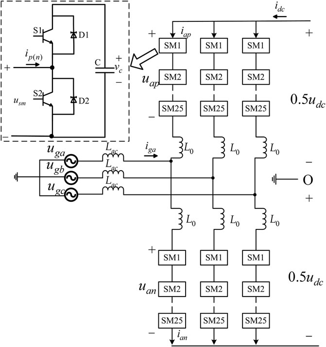
FIGURE 1. Structure of MMC.
MMC is a complex AC-DC coupling system. The common-mode and differential-mode component representation is introduced to analyze the coupling system.
Defining the common-mode component of variable x is
The differential-mode component of variable x is
where xjp (xjn) is the upper (lower) arm variable of phase j.
The arm current dynamics of phase j are
Let
Eq. 5 shows that the differential-mode current
When the switch S1 is on and S2 is off, Usm is equal to the capacitor voltage. When the switch S2 is on and S1 is off, Usm is zero. Arm voltage is obtained from capacitor voltage by PSC-PWM. The relationship between the arm voltage and the capacitor voltage is
where vjpc (vjnc) is the sum of upper (lower) arm capacitor voltages, mjp and mjn are the modulation indices.
Let
Supposed that the volatge balance control of submodule capacitor is realized for each upper or lower arm, and then the dynamics of capacitor voltages are
Adopting the common-mode and differential-mode component representation, Eqs 11 and 12 can be expressed as
It shows that the common-mode component and the differential-mode component of the capacitor voltage have complex nonlinear characteristics.
According to (Eqs 5, 6, 9, 10, 13, 14), the differential-mode current
where
3 AC Power Decoupling Control of Modular Multilevel Converter Based on Linear Active Disturbance Rejection Control Theory
3.1 AC Power Modeling of Modular Multilevel Converter
MMC can exchange active power and reactive power with ac-grid. From Figure 1, ac current in the three-phase stationary coordinates is
Power is usually analyze in the dq rotating coordinates. The relationship between the three-phase stationary coordinates and dq rotating coordinates is shown in Figure 2(Lu et al., 2018). We can get
where
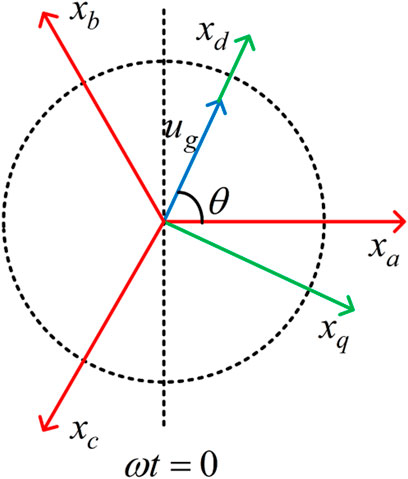
FIGURE 2. Relationship between stationary coordinates and dq rotating coordinates.
When the d-axis of the rotating coordinates is aligned with the grid voltage space vector, that is ugq = 0, the ac active power and reactive power can be calculated as
where active power is determined by
The differential-mode arm current in eq. 5 can be expressed in dq rotating coordinates as
Where Ls = L0/2 + Lac.
According to Eq. 16, we can get
where veqc is the actual value of the sum of the upper (lower) arm capacitor voltages. Eqs 13 and 14 show that veqc is nonlinear and hard to measure, so it is difficult to determine the control variables
3.2 AC Power Decoupling Controller Design Based on Linear Active Disturbance Rejection Control Theory
The structure of LADRC is shown in Figure 3. LADRC is composed of tracking differentiator (TD), linear extended state observer (LESO), and linear state error feedback control law (LSEF). TD can not only overcome the interference noise by obtaining differential signals, but also make reasonable arrangements for the transition process. In other words, TD realizes the fast tracking of reference signal without overshoot and gives the tracking signals of all-order derivatives of reference signal. LESO is based on the development of the traditional observer, which takes the input and output of the control object as one of its inputs. The all-order derivatives of the plant state and the total disturbance variables can be observed through LESO. An obvious advantage of ESO is that it does not rely on the detailed mathematical model for generating disturbances, nor does it need to measure its role directly. LSEF generates the control signal using the output error between the TD and LESO. The mathematical description of one-order LADRC is shown as followings.
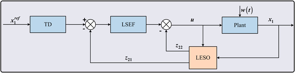
FIGURE 3. Structure of LADRC.
One-order TD is
where z11 is the tracking signal of reference input
Two-order LESO is
where z21 is the estimated value of the plant state x1. z22 is the estimated value of the whole disturbance, which including w(t) and other parameter uncertainties. k21 and k22 are gain coefficients.
LSEF control law is
where k are the gain coefficient.
Eq. 21 can be expressed as
Where
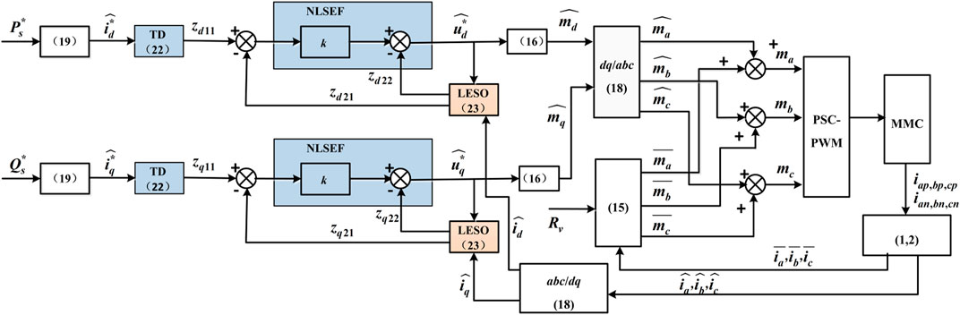
FIGURE 4. Power decoupling control diagram of MMC.
4 Small-Signal Stability Analysis of Modular Multilevel Converter Based Three-Terminal AC/DC Distribution Network
Tangjiawan town is located in Zhuhai city, China. With the continuous progress of industrial park, the load of Tangjiawan town has increased too fast. If only Tangjiawan station supplies power, the power supply radius will be too long, the reliability is low, and the line loss is high. In order to improve the power supply quality and reliability, two 10kV buses are introduced from Jishan station and connected with the 10 kV bus of Tangjiawan station, so as to increase the load transfer capacity of Tangjiawan station and reserve capacity of grid accident. The topology of Tangjiawan-Jishan1 -Jishan2 AC/DC distribution network demonstration project is shown in Figure 5. The rated capacity of Tangjiawan, Jishan1, and Jishan2 station is 20, 10, and 10 MVA individually. The rated DC-bus voltage is ±10 kV and the rated AC voltage is 10.5 kV.
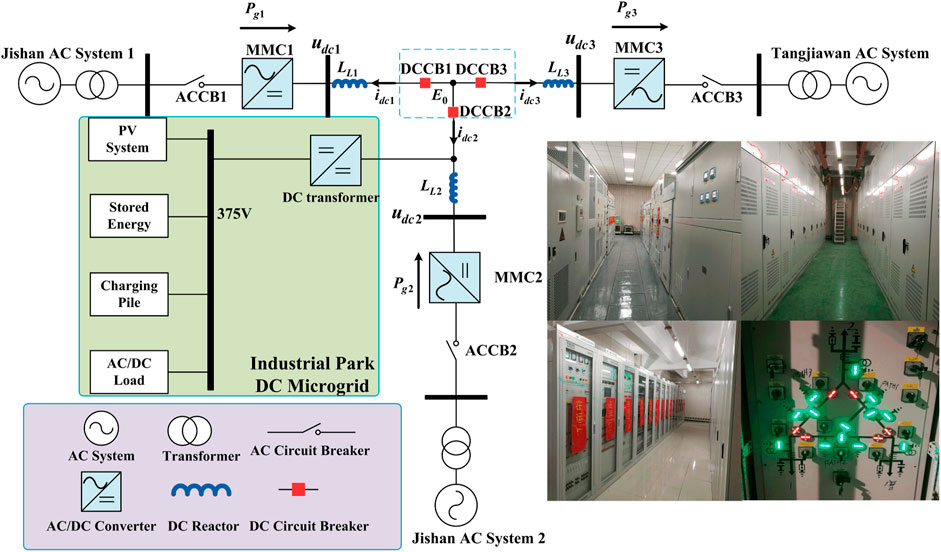
FIGURE 5. Topology of Tangjiawan-Jishan1-Jishan2 AC/DC distribution network.
Although MMC has the same hardware topology, it can work as power station or voltage station. So the operation mode of MMC based three-terminal AC/DC distribution network is versatile. In this paper, the master-slave operation mode is studied according to the engineering application, that is, Tangjiawan Station is voltage station and Jishan1 and Jishan two stations are power stations. The instantaneous-value model of MMC is too complicated to the small-signal stability analysis. In order to simplify the analysis, averaged-value model is needed.
4.1 Averaged-Value Model of Modular Multilevel Converter Power Station
According to Eq. 14, the differential-mode component of capacitor voltage is ac variables and can be neglected based on the switching period. The common-mode component of capacitor voltage is balanced, that is
When common-mode component of arm current is balanced, there is
According to Eqs 7, 9, 12, 26, 27 and the law of energy conservation, the state equation of the equivalent capacitance is
where the equivalent capacitance Ceq = 6C/N and Pg is AC active power controlled by LADRC.
According to Eqs 6, 9, 12, 26, 27, the state equation of the DC current
The linearized model of the Eqs 28 and 29 is
where veqc0 and ieqc0 are the steady-state operating points satisfying the following equations.
4.1.1 Rv = 0
When the virtual resistance is 0, the equilibrium point is
where veqc0 is determined by the external DC voltage source. ieqc0 is determined according to the law of conservation of power. The different choices of
4.1.2 Rv ≠ 0
When the virtual resistance is nonzero, the equilibrium point is
where
where
So the stable region is that
4.2 Small-Signal Stability Analysis of Three-Terminal Modular Multilevel Converter Based DC Grid
The nodal equation of DC network is
where LL1, LL2, LL3 are the DC line inductors and E0 is the nodal voltage at the common connection point.
The relationship between voltage and current of MMC3 is
where E is the terminal voltage of MM3, the output voltage control can be seen in (Li et al., 2018) and is not discussed in detail in this paper.
According to (Eq. 30, 36, 37), the linearization model of three-terminal MMC based DC grid is
The operation condition is that active power of MMC1 is −2 MW and that of MMC2 is 1 MW, the arm inductor is 7 mH and DC inductor is 4 mH. Figure 6 shows the root locus. there are two pairs of conjugate complex roots in the left half plane. With the increase of Rv, the roots gradually moves away from the virtual axis, which indicates that Rv can enhance the stability of DC grid.
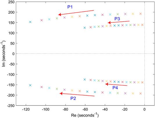
FIGURE 6. Root locus with increase of Rv.
Figure 7 shows the amplitude frequency characteristics of the transfer function Δidc3/ΔPg1. When there is no virtual resistor, there are two low frequency resonance points in bode diagram, which are 22.1 and 30.6 Hz respectively. The resonance peak value at 22.1 Hz is obviously higher than that at 30.6 Hz. So the main resonance frequency of DC grid is about 22.1 Hz. When the virtual resistor is added, the resonance peak value attenuates greatly. Virtual resistor can effectively suppress the system oscillation and improve the transient performance of DC grid.
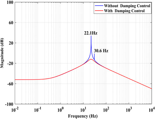
FIGURE 7. Bode diagram of Δidc3/ΔPg1 (Rv = 1).
5 Simulations of Modular Multilevel Converter Based Three-Terminal AC/DC Distribution Network
The number of sub-modules N = 25. The sub-module capacitance is 13 mF and the switching frequency is 300 Hz. The phase leg reactor is 7 mH and the rated voltage of AC and DC are 10kVac and 20 kVdc individually. PSC-PWM is adopted and the electromagnetic transient model of MMC based three-terminal AC/DC distribution network is established on PSCAD.
Figures 8–13 shows the decoupling power control of MMC under LADRC and PI controller. Figure 8 shows the simulation results of active power step response. Active power immediately responds step disturbance and changes from 1 MW to −1 MW at 0.2 s and changes from −1 to 1 MW at 0.4 s. Reactive power also instantly responds step disturbance and varies from 0.5 Mvar to −0.5 Mvar at 0.6 s and varies from −0.5 Mvar to 0.5 Mvar at 0.8 s. Obviously, it results in a little fluctuations when step disturbance occurs momentarily. Figure 9 is the differential-mode component of arm current which has waveform aberration. Figure 10 are the common-mode component of arm current with a little more waveform burred. As shown in Figure 11, The each phase peak AC voltage output of MMC has reached at about 8.17 kV.Figure 12 shows the derivatives of LADRC. Zd22 and Zq22 are estimated of total system disturbances. Figure 13 is the sub-module capacitor voltages, which is balanced and the capacitor voltage difference is less than 1.2%. In briefly, the simulation results reveal that LADCR can successfully realize the decoupling control of AC active power and reactive power. Compared with PI controller, LADRC has the advantages of smoother power waveform, faster response and lower overshoot, etc.
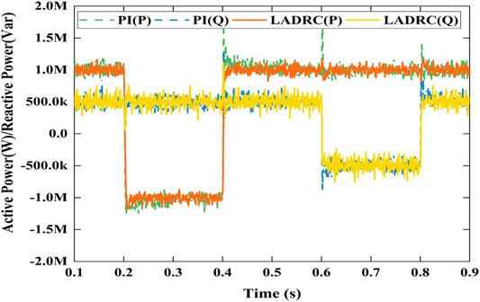
FIGURE 8. Active power and reactive power.
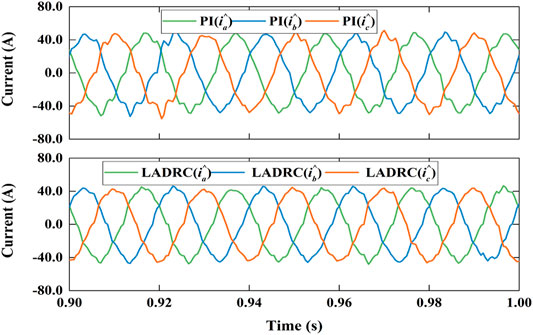
FIGURE 9. Differential-mode component of arm current.
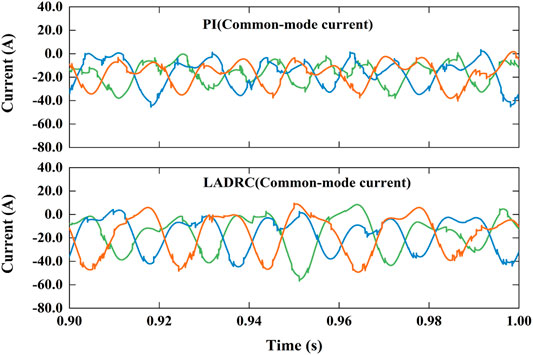
FIGURE 10. Common-mode component of arm current.
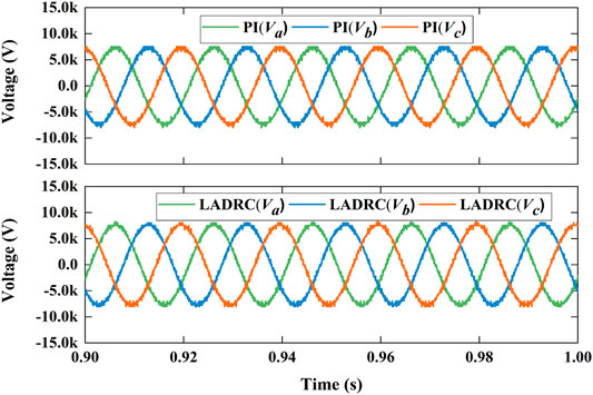
FIGURE 11. AC voltage of MMC.
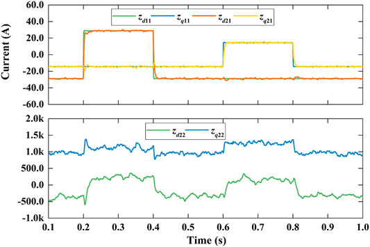
FIGURE 12. State variables of LADRC.
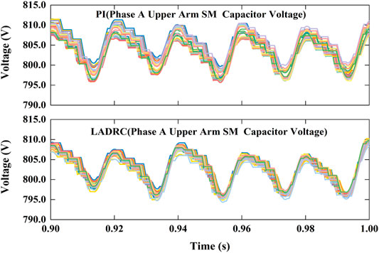
FIGURE 13. Sub-module capacitor voltage.
Figure 14 shows variables of MMC based three-terminal DC grid. When there is no virtual resistor, there exists continuous oscillation in DC-bus voltage, DC current, capacitor voltage and active power because of lack of damping. When virtual resistor is added at t = 0.5 s, the oscillation can be suppressed quickly and the DC-bus voltage can be stabilized at 20 kV. When virtual resistor is added, the stable capacitor voltage is determined by the active power.
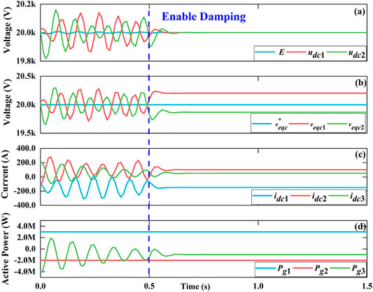
FIGURE 14. Variables of MMC based three-terminal DC grid (Rv = 1).
6 Experiments on Tangjiawan-Jishan1-Jishan2 AC/DC Distribution Network
6.1 Active Power Step Test of Jishan2 Station
Figure 15 shows system waveforms with active power step change in Jishan2 station. As shown in Figure 15A, active power of Jishan1 station is constant at −1 MW. Active power of Jishan2 station changes from −1 to 1 MW at t1, and from 1 MW to −1 MW at t2. Accordingly, active power of Tangjiawan station changes from 2 to 0 MW at t1, and from 0 to 2 MW at t2. Reactive power of Jishan1 remains 1 MVar. There are fluctuations in reactive power of Jishan2 station and Tangjiawan station at the moment of active power change. But reactive power of Jishan2 and Tangjiawan will remain stable at 1Mvar and 0Mvar when active power is stable as shown in Figure 15B. Figure 15C shows the DC-bus voltage. The DC-bus voltage of Tangjiawan station is constant at 20 kV. There exist slight fluctuations in DC-bus voltages of Jishan1 station and Jishan2 station at the moment of active power change, but the DC-bus voltages still are within the reasonable range.
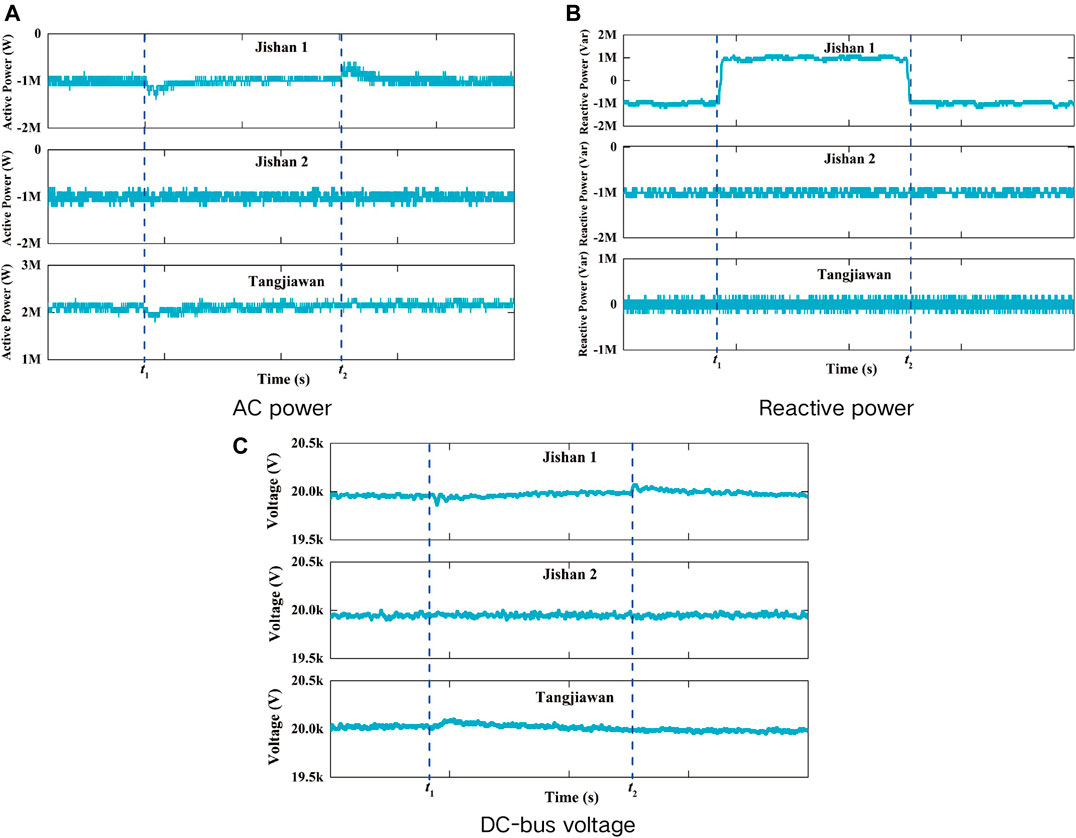
FIGURE 15. Active power step change in Jishan2 station.
6.2 Reactive Power Step Test of Jishan1 Station
Figure 16 shows the system waveforms with reactive power step change in Jishan1 station. As shown in Figure 16A, active power of Jishan1 station, Jishan2 station, and Tangjiawan station is constant at −1, −1, and 2 MW respectively. Figure 16B shows that reactive power of Jishan1 station changes from -1Mvar to 1Mvar at t1, and changes from 1 to −1 Mvar at t2. Reactive power of Jishan2 station and Tangjiawan station remains unchanged at -1Mvar and 0Mvar individually. Figure 16C shows that the reactive power step change of Jishan1 has influence on the DC-bus voltages of Jishan1 station and Tangjiawan station, but the DC-bus voltage is still within the reasonable range.
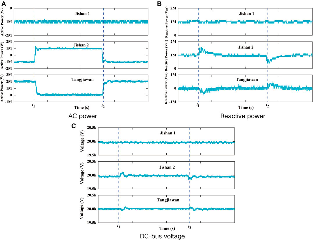
FIGURE 16. Reactive power step change in Jishan1 station.
6.3 Active Power Flow Reversal Test of Jishan1 Station
Figure 17 is the experiments results of active power reversal test of Jishan1 station. Figure 17A shows that Jishan2 station active power still remains 1 MW when Jishan1 station active power flow reversal starts at t1 and completes at t2 with active power varies from 1 to −1 MW. However, Tangjiawan station active power responds flow reversal immediately with active power varies from -2 to 0 MW. Figure 17B shows that active power flow reversal can influence reactive power of Jishan1 and Tangjiawan station, but the reactive power of Jishan1 station and Tangjiawan station still remains 1 Mvar and 0 Mvar respectively with waveform burr increased. Figure 17C shows that DC bus voltage of three converters station is stable at 20 kV, but Jishan1 station DC bus voltage fluctuates a little bit more than other two stations.
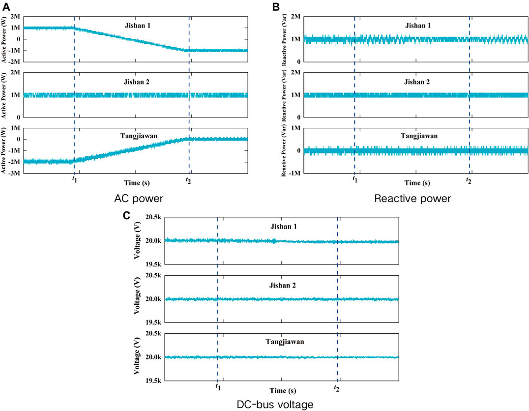
FIGURE 17. Active power flow reversal in Jishan1 station.
7 Conclusion
A novel instantaneous-value model of MMC is derived by introducing the differential-mode and common-mode component representation. Then, ac power modeling of MMC is established based on the PSC-PWM strategy and power decoupling control based on LADRC is realized. Simplified average-value model of MMC power station is deduced and the small signal stability analysis of three-terminal DC grid is carried out. Simulation and experiment results of the Tangjiawan-Jishan1-Jishan2 AC/DC distribution network demonstration project verify that the power decoupling strategy based on LADRC is better than PI controller. The virtual resistor can greatly improve the transient performance and system stability. The modeling and analysis method proposed in this paper is concise and effective. The research of this paper is the expansion of MMC application in the field of distribution network. MMC based multi-terminal AC/DC distribution network can realize the multidirectional power flow among AC-grids, which can greatly improve the power supply reliability.
Data Availability Statement
The raw data supporting the conclusion of this article will be made available by the authors, without undue reservation.
Author Contributions
ZX and HY: conceptualization, data curation, methodology and writing. GZ and LL: formal analysis and simulation study. PW and CJ: reagents/materials/analysis.
Funding
This journal was supported in part by Natural Science Foundation of Guangdong Province under Grant (2018A0303130111), in part by Open Project of Anhui Key Laboratory of Intelligent Building and Building Energy Saving under Grant (IBES2020KF10), in part by the Guangzhou Science and Technology Planning Project under Grant (201902020003), in part by the Guangdong Special Project in Key Field of Artificial Intelligence for Ordinary University under Grant (2019KZDZX1004), in part by the Guangzhou Key Laboratory Project of Intelligent Building Equipment Information Integration and Control under Grant (202002010003), in part by the Guangzhou Yuexiu District Science and Technology Plan Major Project under Grant (2019-GX-010).
Conflict of Interest
HY was employed by the company Heyuan Power Supply Bureau of Guangdong Power Grid Co. Ltd.
The remaining authors declare that the research was conducted in the absence of any commercial or financial relationships that could be construed as a potential conflict of interest.
Publisher’s Note
All claims expressed in this article are solely those of the authors and do not necessarily represent those of their affiliated organizations, or those of the publisher, the editors and the reviewers. Any product that may be evaluated in this article, or claim that may be made by its manufacturer, is not guaranteed or endorsed by the publisher.
References
Adam, G. P., and Williams, B. W. (2014). Half- and Full-Bridge Modular Multilevel Converter Models for Simulations of Full-Scale HVDC Links and Multiterminal DC Grids. IEEE J. Emerg. Sel. Top. Power Electron. 2 (4), 1089–1108. doi:10.1109/jestpe.2014.2315833
Ahmed, N., Angquist, L., Mehmood, S., Antonopoulos, A., Harnefors, L., Norrga, S., and Nee, H. (2016). “Efficient Modeling of an Mmc-Based Multiterminal Dc System Employing Hybrid Hvdc Breakers,” in 2016 IEEE Power and Energy Society General Meeting (PESGM), Boston, MA, July 17–21, 2016, 1. doi:10.1109/pesgm.2016.7741765
Alassi, A., Bañales, S., Ellabban, O., Adam, G., and MacIver, C. (2019). Hvdc Transmission: Technology Review, Market Trends and Future Outlook. Renew. Sustain. Energ. Rev. 112, 530–554. doi:10.1016/j.rser.2019.04.062
Alonge, F., Cirrincione, M., D'Ippolito, F., Pucci, M., and Sferlazza, A. (2017). Active Disturbance Rejection Control of Linear Induction Motor. IEEE Trans. Ind. Applicat. 53 (5), 4460–4471. doi:10.1109/tia.2017.2697845
Angquist, L., Antonopoulos, A., Siemaszko, D., Ilves, K., Vasiladiotis, M., and Nee, H.-P. (2011). Open-Loop Control of Modular Multilevel Converters Using Estimation of Stored Energy. IEEE Trans. Ind. Applicat. 47 (6), 2516–2524. doi:10.1109/tia.2011.2168593
Antonopoulos, A., Angquist, L., and Nee, H. P. (2009). “On Dynamics and Voltage Control of the Modular Multilevel Converter,” in 2009. EPE ’09. 13th European Conference on, Barcelona, Spain, September 8–10, 2009 (Power Electronics and Applications).
Bergna Diaz, G., Suul, J. A., and D’Arco, S. (2015). “Small Signal State-Space Modeling of Modular Multilevel Converters for System Stability Analysis,” in 2015 IEEE Energy Conversion Congress and Exposition (ECCE), Montreal, Canada, September 20–24, 2015, 5822–5829. doi:10.1109/ecce.2015.7310477
Chen, Y. C., Dhople, S. V., Guggilam, S. S., Dall’Anese, E., and Giannakis, G. B. (2016). Scalable Optimization Methods for Distribution Networks with High Pv Integration. IEEE Trans. Smart Grid 7 (4), 2061–2070. doi:10.1109/TSG.2016.2543264
Chen, W.-H., Yang, J., Guo, L., and Li, S. (2016). Disturbance-Observer-Based Control and Related Methods-An Overview. IEEE Trans. Ind. Electron. 63 (2), 1083–1095. doi:10.1109/tie.2015.2478397
Debnath, S., Qin, J., Bahrani, B., Saeedifard, M., and Barbosa, P. (2015). Operation, Control, and Applications of the Modular Multilevel Converter: A Review. IEEE Trans. Power Electron. 30 (1), 37–53. doi:10.1109/tpel.2014.2309937
Friedrich, K. (2010). “Modern Hvdc Plus Application of Vsc in Modular Multilevel Converter Topology,” in 2010 IEEE International Symposium on Industrial Electronics, Bari, Italy, July 4–7, 2010, 3807–3810. doi:10.1109/isie.2010.5637505
Guan, M., and Xu, Z. (2012). Modeling and Control of a Modular Multilevel Converter-Based Hvdc System under Unbalanced Grid Conditions. IEEE Trans. Power Electron. 27 (12), 4858–4867. doi:10.1109/tpel.2012.2192752
Harnefors, L., Antonopoulos, A., Norrga, S., Angquist, L., and Nee, H.-P. (2013). Dynamic Analysis of Modular Multilevel Converters. IEEE Trans. Ind. Electron. 60 (7), 2526–2537. doi:10.1109/tie.2012.2194974
Kotb, O., Ghandhari, M., Eriksson, R., and Sood, V. K. (2016). On Small Signal Stability of an Ac/dc Power System with a Hybrid Mtdc Network. Electric Power Syst. Res. 136, 79–88. doi:10.1016/j.epsr.2016.02.004
Lesnicar, A., and Marquardt, R. (2004). “An Innovative Modular Multilevel Converter Topology Suitable for a Wide Power Range,” in Power Tech Conference, Bologna, Italy, June 23–26, 2003.
Li, Y., Tang, G., Ge, J., He, Z., Pang, H., Yang, J., et al. (2018). Modeling and Damping Control of Modular Multilevel Converter Based Dc Grid. IEEE Trans. Power Syst. 33 (1), 723–735. doi:10.1109/tpwrs.2017.2691737
Li, Y., Liu, K., Liao, X., Zhu, S., Huai, Q., and Huai, Q. (2019). A Virtual Impedance Control Strategy for Improving the Stability and Dynamic Performance of VSC-HVDC Operation in Bidirectional Power Flow Mode. Appl. Sci. 9 (15), 3184. doi:10.3390/app9153184
Liu, C., Luo, G., Wencong, T. U., and Wan, H. (2017). Servo Systems with Double Closed-Loops Based on Active Disturbance Rejection Controllers. Chin. Soc. Electr. Eng. 37 (23), 7032–7039. doi:10.13334/j.0258-8013.pcsee.161957
Liu, C., Luo, G., Duan, X., Chen, Z., Zhang, Z., and Qiu, C. (2020). Adaptive LADRC-Based Disturbance Rejection Method for Electromechanical Servo System. IEEE Trans. Ind. Applicat. 56 (1), 876–889. doi:10.1109/tia.2019.2955664
Lu, X., Xiang, W., Lin, W., and Wen, J. (2018). Small-Signal Modeling of Mmc Based Dc Grid and Analysis of the Impact of Dc Reactors on the Small-Signal Stability. Int. J. Electr. Power Energ. Syst. 101, 25–37. doi:10.1016/j.ijepes.2018.01.046
Marquardt, R. (2010). “Modular Multilevel Converter: An Universal Concept for Hvdc-Networks and Extended Dc-Bus-Applications,” in The 2010 International Power Electronics Conference - ECCE ASIA, Sapporo, Japan, June 21–24, 2010, 502–507. doi:10.1109/ipec.2010.5544594
Marquardt, R. (2011). “Modular Multilevel Converter Topologies with Dc-Short Circuit Current Limitation,” in IEEE International Conference on Power Electronics & Ecce Asia, Jeju, Korea (South), May 30–June 3, 2011. doi:10.1109/icpe.2011.5944451
Mithulananthan, N., Shah, R., and Bansal, R. C. (2013). Oscillatory Stability Analysis with High Penetrations of Large-Scale Photovoltaic Generation. Energ. Convers. Manage. 65, 420–429. doi:10.1016/j.enconman.2012.08.004
Rao, H. (2015). Architecture of Nan'ao Multi-Terminal VSC-HVDC System and its Multi-Functional Control. CSEE Power Energ. Syst. 1 (1), 9–18. doi:10.17775/cseejpes.2015.00002
Saad, H., Peralta, J., Dennetiere, S., Mahseredjian, J., Jatskevich, J., Martinez, J. A., et al. (2013). Dynamic Averaged and Simplified Models for Mmc-Based Hvdc Transmission Systems. IEEE Trans. Power Deliv. 28 (3), 1723–1730. doi:10.1109/tpwrd.2013.2251912
Trinh, N.-T., Zeller, M., Wuerflinger, K., and Erlich, I. (2016). Generic Model of MMC-VSC-HVDC for Interaction Study with AC Power System. IEEE Trans. Power Syst. 31 (1), 27–34. doi:10.1109/tpwrs.2015.2390416
Vasiladiotis, M., Cherix, N., and Rufer, A. (2014). Accurate Capacitor Voltage Ripple Estimation and Current Control Considerations for Grid-Connected Modular Multilevel Converters. IEEE Trans. Power Electron. 29 (9), 4568–4579. doi:10.1109/tpel.2013.2286293
Wan, X., Li, Y., and Peng, M. (2018). Modelling, Analysis and Virtual Parallel Resistor Damping Control of VSC‐Based DC Grid Using Master-Slave Control Mode. IET Generation, Transm. Distribution 12 (9), 2046–2054. doi:10.1049/iet-gtd.2017.1021
Wang, J., and Wang, P. (2019). Decoupled Power Control for Direct-Modulation-Based Modular Multilevel Converter with Improved Stability. IEEE Trans. Ind. Electron. 66 (7), 5264–5274. doi:10.1109/tie.2018.2870352
Wang, P., Liu, X., and Loh, P. C. (2011). A Hybrid Ac/dc Microgrid and its Coordination Control. IEEE Trans. Smart Grid 2 (2), 278–286. doi:10.1109/TSG.2011.2116162
Wang, P., Zhang, X.-P., Coventry, P. F., and Zhang, R. (2016). Start-Up Control of an Offshore Integrated Mmc Multi-Terminal Hvdc System with Reduced Dc Voltage. IEEE Trans. Power Syst. 31 (4), 2740–2751. doi:10.1109/tpwrs.2015.2466600
Wang, Y., Yuan, Z., and Fu, J. (2016). A Novel Strategy on Smooth Connection of an Offline Mmc Station into Mtdc Systems. IEEE Trans. Power Deliv. 31 (2), 568–574. doi:10.1109/tpwrd.2015.2437393
Wang, G., Liu, R., Zhao, N., Ding, D., and Xu, D. (2019). Enhanced Linear Adrc Strategy for Hf Pulse Voltage Signal Injection-Based Sensorless Ipmsm Drives. IEEE Trans. Power Electron. 34 (1), 514–525. doi:10.1109/tpel.2018.2814056
Xiang, W., Lin, W., An, T., Wen, J., and Wu, Y. (2017). Equivalent Electromagnetic Transient Simulation Model and Fast Recovery Control of Overhead Vsc-Hvdc Based on Sb-Mmc. IEEE Trans. Power Deliv. 32 (2), 778–788. doi:10.1109/tpwrd.2016.2607230
Yang, H., Dong, Y., Li, W., and He, X. (2017). Average-Value Model of Modular Multilevel Converters Considering Capacitor Voltage Ripple. IEEE Trans. Power Deliv. 32 (2), 723–732. doi:10.1109/tpwrd.2016.2555983
Yang, H., Li, W., Lin, L., and He, X. (2018). Decoupled Current Control with Synchronous Frequency Damping for Mmc Considering Sub-Module Capacitor Voltage Ripple. IEEE Trans. Power Deliv. 33 (1), 419–428. doi:10.1109/tpwrd.2017.2721961
Keywords: MMC, power decoupling control, small signal, stability analysis, virtual resistor
Citation: Xianyong Z, Zijuan G, Yaohong H, Li L, Weikuan P and Jian C (2021) Power Decoupling Control of MMC and Small-Signal Stability Analysis of AC/DC Distribution Network With Renewable Energy. Front. Energy Res. 9:734797. doi: 10.3389/fenrg.2021.734797
Received: 01 July 2021; Accepted: 04 August 2021;
Published: 04 October 2021.
Edited by:
Yaxing Ren, University of Warwick, United KingdomReviewed by:
Weiyu Wang, Changsha University of Science and Technology, ChinaZhi Zhang, Dongguan University of Technology, China
Copyright © 2021 Xianyong , Zijuan , Yaohong , Li, Weikuan and Jian. This is an open-access article distributed under the terms of the Creative Commons Attribution License (CC BY). The use, distribution or reproduction in other forums is permitted, provided the original author(s) and the copyright owner(s) are credited and that the original publication in this journal is cited, in accordance with accepted academic practice. No use, distribution or reproduction is permitted which does not comply with these terms.
*Correspondence: Li Li, bGlsaWFydGljbGVAMTYzLmNvbQ==