 Jun Xu
 Lei Gao
- School of Electrical and Electronic Engineering, North China Electric Power University, Beijing, China
Abstract-Fault current limiters (FCLs) can suppress the rise of short-circuit fault currents in voltage source converter (VSC) based DC grids. However, the power electronic switches of FCLs need extra source equipment to supply the required power, which increases complexity and cost. This paper presents three kinds of self-powered solid-state FCLs (SSFCLs). The proposed self-powered SSFCLs detect short-circuit faults by sensing fault current increases and draw energy from the fault DC line to automatically drive the power electronic switches. The self-powered SSFCLs are equipped with a self-powered supply system (SPSS). The SPSS obtains energy from the magnetic field induced by short-circuit fault current using magnetic-coupling mutual inductance coils. In PSCAD/EMTDC, the proposed self-powered SSFCLs are placed directly on the DC line without external power supply equipment. When a short-circuit fault occurs, the simulation results verify that the proposed self-powered SSFCLs can rapidly acquire power to drive the power electronic switches and then suppress the rise of the fault current. The proposed self-powered SSFCL prototypes provide a solution for decreasing the cost and complexity associated with installing extra source equipment.
Introduction
Voltage source converter-high voltage direct current (VSC-HVDC) systems are known to be superior to AC networks (AC distribution networks or AC transmission networks) and to line commutated converter-high voltage direct current (LCC-HVDC) systems in the integration of long-distance power transmission and renewable energy sources (Flourentzou et al., 2009; Lyu et al., 2019; Zhang et al., 2021). Different from AC systems, in VSC DC grids, the short-circuit fault breaking operation is difficult due to the lack of zero crossings. A strict current breaking requirement is needed for a DC circuit breaker (DCCB) to cut off the DC line within 5 ms (Heidary et al., 2019). DC fault current limiters (DCFCLs) can help decrease the current breaking stress of DCCBs by limiting the rise of the fault current (Yang et al., 2019). Installation of DCCBs and DCFCLs can rapidly and reliably clear the short-circuit faults in VSC DC grids. Notably, the operation of DCFCLs and DCCBs relies on various power electronic switches and gate drivers. Thus, one major problem with DCFCLs and DCCBs is the power supply of the mechanical switch and the gate driver for the power electronic components (Zhang et al., 2020).
Power electronic components in AC systems can take power from AC lines by mutual inductance or instrument transformers. Two novel power supplies for online condition monitoring systems are proposed for AC systems in Lin Du et al. (2010), Wu et al. (2013). A specially designed coil-based magnetic energy harvester (CMEH) was proposed in Lin Du et al. (2010), and a specially designed Rogowski coil for power transmission lines was proposed in Wu et al. (2013). This is widely considered to be a good method for power electronic devices of AC circuit breakers (ACCBs) to acquire power from AC lines.
However, for DCCBs and DC FCLs, the direct acquisition of power from AC lines is typically a complex and difficult problem. In addition, unlike the power electronic components in AC/DC converters that can acquire power from the primary system by an extra DC/DC converter (Li et al., 2015; Li et al., 2016; Zhang et al., 2020), the power electronic switches in DCCBs and FCLs are in the on-state most of the time, which makes it difficult for them to directly acquire energy from DC lines.
Some power supply methods have been proposed to solve the power-acquisition problems in different networks. In Kobayashi et al. (2006), Dondi et al. (2008), a solar-cell power supply was proposed to drive the monitoring circuits. However, this power supply device is dependent on the weather and necessitates regular maintenance work, such as changing the energy storage device and clearing the solar panel. In Hafner (2011), Zhou et al. (2015), Zhang et al. (2016), a type of power supply method called power over fiber was presented. This method can deliver power through laser light via optical fibers over long distances. This can theoretically solve the power supply problem. However, the low conversion efficiency of this method results in low practicability in large-scale power supply applications.
In VSC DC grids, the DCFCLs and DCCBs are installed in the DC line. It is difficult for them to take power from DC lines by instrument transformers. The capacitor can be used as the power supply component to drive the IGBT switch in DCFCLs and DCCBs. The capacitor can be parallel-connected with the DCFCLs or the DCCBs. The capacitor needs to charge first, and then the detecting equipment, sensor and driving component of the power electronics receive power from the capacitor. However, the cost and complex will increase with an extra increase in the capacitor. The voltage across the DCFCLs or the DCCBs is always needed, which is detrimental to the normal operation of DCFCLs or DCCBs. Another common way to solve the power supply problem of power electronic switches is to install an extra power supply system. A power electronic switch driver was designed for a bidirectional solid-state circuit breaker (SSCB) in Urciuoli and Veliadis (2011). However, one major drawback of this driver is that it relies on complex and costly overcurrent sensing circuitry. One or more isolated auxiliary power supplies are needed to power up the control electronics of the SSCB (Miao et al., 2015). This means a sharp increase in cost and complexity. The cost of designing FCLs has been a complex problem that is difficult to solve. If the power supply systems of FCLs rely on extra devices, the cost will be greatly increased.
These problems have attracted increasing attention in the field of DC transmission technology. Some self-powered supply system (SPSS) techniques without adding extra power supply devices have been developed to solve these problems. Zhang et al. (2020) presents a high-voltage isolated power supply system for complex multiple electrical types of equipment in hybrid DCCBs based on the mains frequency cascaded isolation transformer network and high frequency LLC converter. This was also the first description of the power supply system for high-voltage level circuit breakers, and it has considerable guiding value for the research of similar high-voltage equipment. In Miao et al. (2015), a self-powered ultrafast SSCB with a silicon carbide (SiC) junction gate field-effect transistor (JFET) was proposed, which can detect short circuit faults by sensing its drain-source voltage rise and draw power from the fault condition to turn and hold off the SiC JFET. The new two-terminal SSCB can be directly placed in a circuit branch without requiring any external power supply or extra wiring. In Fu et al. (2017), a coupling method of power supplies was proposed for spacecraft hollow cathode power supply applications. The coupling inductance is used in ignitor-keeper supply and heater supply devices, which can reliably acquire energy. The design principle in Fu et al. (2017) is of special interest for SPSS devices of FCLs.
To date, various FCLs have been proposed to suppress short-circuit faults in DC grids (Wu et al., 2011; Jalilian et al., 2015; Radmanesh et al., 2015; Jalilian et al., 2017; Liu et al., 2017; Zhang et al., 2017). The installation of FCLs can decrease the current breaking stress of DCCBs. However, the power supplies of FCLs have problems similar to those of DCCBs. However, the proposed SPSS methods in Lin Du et al. (2010), Urciuoli and Veliadis (2011), Wu et al. (2013), Miao et al. (2015), Fu et al. (2017), Zhang et al. (2020) cannot be directly used to design SPSSs for FCLs. Few studies have focused on the application of SPSSs to drive the power electronic switch of FCLs. In Jalilian et al. (2015), a novel DC-link fault current limiter (DLFCL)-based fault ride-through (FRT) scheme was proposed to improve the FRT capability in inverter-based distributed generation (IBDGs) units. The employed DLFCL does not need any control, measurement and gate driving system and is composed of a diode-bridge and a non-superconductor (copper coil) that is modeled by a resistor and an inductor. However, the design principle of SPSSs for FCLs was not introduced in Jalilian et al. (2015).
The power electronics of DCFCLs in this paper are composed of fully controllable semiconductor switches such as IGBTs and IGCTs. The power supply components are inevitable. Thus, it is critical to develop and describe the SPSSs for FCLs. To design SPSS for FCLs, three issues need to be considered (Lin Du et al., 2010; Xu et al., 2018a; Xu et al., 2018b):
• The SPSS of the FCLs should rapidly and reliably acquire power in the fault state.
• The SPSS of the FCLs should not influence the equivalent inductance of the FCLs.
• The SPSS of the FCLs should be low cost and reliable.
This paper presents three kinds of self-powered solid-state FCLs equipped with the SPSS. This is also the first description of the SPSS for such FCLs, and it may have necessary guiding value for the research of similar FCL equipment. The structure and operation mechanism of three kinds of self-powered FCLs are presented in the following sections. The proposed FCLs mainly consist of a fault current limiting circuit and an energy taking unit. These limiters comprise mutual inductors, power electronic switches, rectifier circuits, and energy storage circuits. The following section introduces the self-powered FCLs: scheme design, operation analysis, and simulation analysis. In addition, the hybrid DCCB and proposed FCLs are installed on the DC side of the DC system. Then, the simulation model is built in PSCAD/EMTDC based on a medium-voltage (20 kV/400 A) DC system in Jiangsu, China. The simulation results show that the proposed self-powered FCLs can limit the short-circuit current and obtain energy from the magnetic field induced by the fault current. The proposed self-powered FCLs take power from the DC fault line and supply energy to IGBT switches without extra power supply devices, which can decrease the cost of FCLs. The energy obtained by three kinds of self-powered FCLs can meet the needs of the driving voltage of each IGBT switch.
Scheme of the Proposed FCLs With SPSSs
Overview of FCLs
In recent years, different types of FCLs, including superconductive fault current limiters (SFCLs) (Zhang et al., 2017), liquid metal current limiters (LMCLs) (Zhang et al., 2017), hybrid fault current limiters (HFCLs) (Liu et al., 2017), and solid-state fault current limiters (SSFCLs) (Radmanesh et al., 2015), have been proposed to mitigate short-circuit fault current. In Jalilian et al. (2017), an innovative DC-link controllable fault current limiter (C-FCL) based FRT scheme for the rotor side converter (RSC) was proposed to improve the FRT capability of the doubly fed induction generator (DFIG). Rotor over-currents are successfully limited during balanced and unbalanced grid faults, even at zero grid voltage. Each FCL has advantages and disadvantages (Nie et al., 2021). In this section, the proposed self-powered FCLs are designed based on SSFCLs (Xu et al., 2018a; Nie et al., 2021). The working operation of the SSFCLs are achieved by changing the on-off state of solid-state switch insulated gate bipolar transistors (IGBTs). The fault current waveforms with or without FCLs are shown in Figure 1.

FIGURE 1. Fault current with FCLs and without FCLs.
Configuration of SSFCLs With SPSSs
Structure of the TTSSFCL With SPSS
The SSFCL structure shown in Figure 2B is a transformer-type SSFCL (TTSSFCL) (Lim et al., 2007).
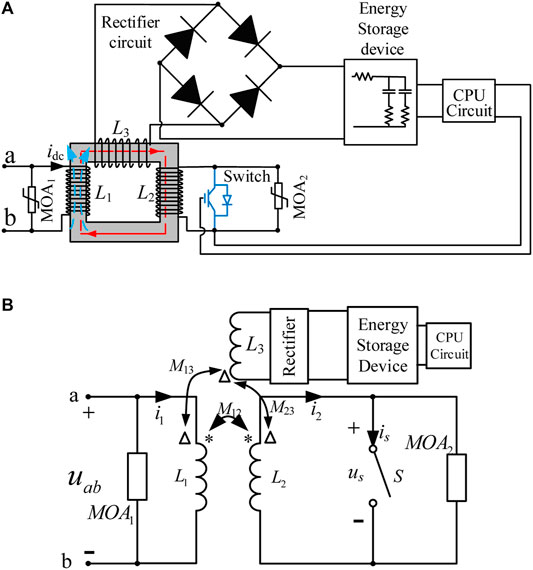
FIGURE 2. Structure of the TTSSFCL with SPSS. (A) Configuration of the TTSSFCL with SPSS. (B) Equivalent circuit of the TTSSFCL with SPSS.
The self-powered TTSSFCL with SPSS comprises the first inductor L1 coupled with the second inductor L2. The power electronic selector switch is connected in parallel with the second inductor to form the main circuit. The power electronic selector switch is composed of several IGBTs. The third inductor L3 is coupled with the first inductor and connected with the rectifier unit and energy storage unit to form the self-powered circuit, as shown in Figure 2A.
The current induced in the third inductor is very low, which means that the third inductor does not influence the equivalent inductance of the TTSSFCL. The metal oxide arrester (MOA) is connected in parallel with power electronic switches as the protection component.
In the normal state, the equivalent inductance of the TTSSFCL is low when the power electronic selector switch is turned on. The equivalent inductance of the TTSSFCL is as follow (Xu et al., 2018a; Nie et al., 2021):
When a short-circuit fault occurs in the DC line and the fault current exceeds the threshold, the power electronic selector switches are turned off. The inductance of the TTSSFCL is greatly increased, and the equivalent inductance is LabO (TTSSFCL) = L1.
The third inductor of SPSS is coupled with the first inductor, and the two ends of the third inductor produce sensing voltage and sensing current when the fault current increases in the first inductor. Then, the energy is stored through the rectifier and energy storage unit to provide the power supply for driving the power electronic switches in the TTSSFCL.
Structure of the PCCSSFCL With SPSS
Based on the structure of the TTSSFCL, two flux-coupling SSFCLs (Xu et al., 2018a) with SPSSs are proposed, as shown in Figures 3, 4. The secondary inductor L2 is connected in parallel with the first inductor L1, and the power electronic selector switch is connected in series with the secondary inductor L2, as shown in Figure 3. The proposed SSFCL in Figure 3 is defined as the parallel-connected coupling SSFCL (PCCSSFCL). Its working mechanism also relies on the operation of the power electronic selector switch.
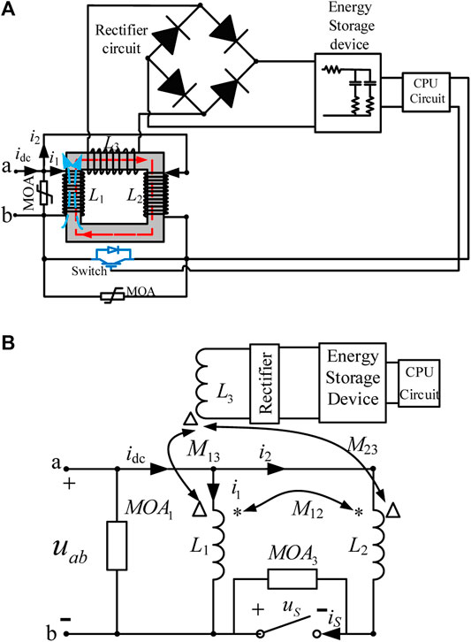
FIGURE 3. Structure of the PCCSSFCL with SPSS. (A) Configuration of the PCCSSFCL with SPSS. (B) Equivalent circuit of the PCCSSFCL with SPSS.
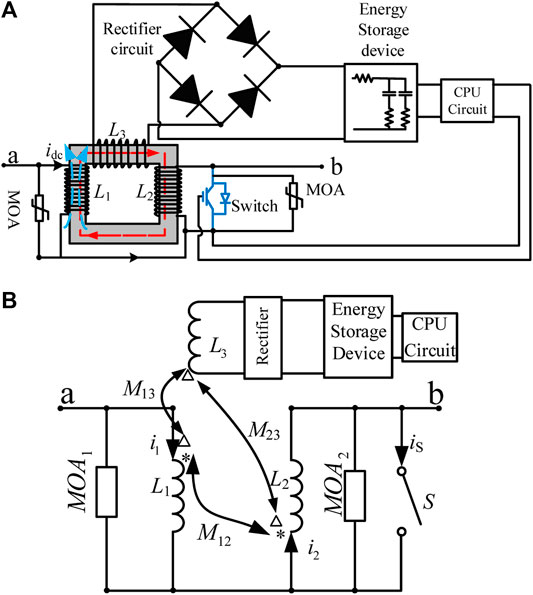
FIGURE 4. Structure of the SCCSSFCL with SPSS. (A) Configuration of the SCCSSFCL with SPSS. (B) Equivalent circuit of the SCCSSFCL with SPSS.
In the normal state, the switches are turned on, and the equivalent inductance of the PCCSSFCL is as follows: (Xu et al., 2018a):
In the fault state, the switches are turned off, and the equivalent inductance is LabO (PCCSSFCL) = L1.
Structure of the SCCSSFCL With SPSS
Another type of SSFCL is the serial-connected coupling SSFCL (SCCSSFCL) (Heidary et al., 2019; Xu et al., 2018a). The two inductors in the main circuit are connected in series, as shown in Figure 4. The power electronic selector switch is connected in parallel with the secondary inductor, as shown in Figure 4. The PCCSSFCL and SCCSSFCL both use additive polarity winding (Hyo-Sang Choi et al., 2009).
In the normal state, the switches are turned on, and the main circuit equivalent inductance is as follows: (Xu et al., 2018a):
In the fault state, the switches are turned off, and the main circuit equivalent inductance is as follows:
Operation Analysis of the Proposed FCL With SPSS
For convenience of comparison, the values of L1, L2, M and MOA are the same in the three types of FCLs, as shown in Figures 2–4. The connections of L1, L2, M12, switch S and MOA are different in the three types of SSFCLs. In the fault state, the equivalent inductance of the self-powered SCCSSFCL is maximized, as shown in the last section
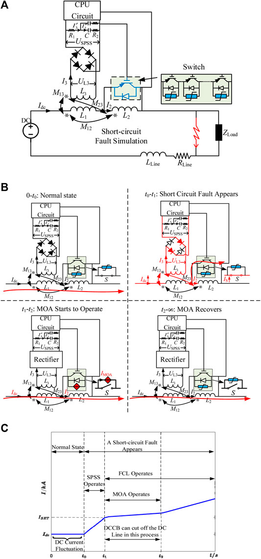
FIGURE 5. SCCSSFCL with SPSS installed on a DC system. (A) Configuration of the SCCSSFCL with SPSS. (B) Different states of the SCCSSFCL with SPSS. (C) Current waveform of the DC system.
As shown in Figure 5A, the voltage drop UL1 across inductor L1 can be expressed as (5). The voltage drop across inductor L3 is induced by the mutual inductance M13 and M23, expressed as (6). The current flow through inductor L3 can be expressed as (7).
In the normal state (0-t0), in an actual DC transmission project, 5–10% current fluctuation may appear due to the voltage ripple of the sub-module capacitors or DC capacitors in the normal state (QingruiTu et al., 2011; Liu et al., 2015; Xu et al., 2017). If the power electronic switches of the SCCSSFCL cannot be turned on, the equivalent inductance of the SCCSSFCL will increase, which will influence the DC current. Thus, the power electronic switches of the SCCSSFCL should be driven to be turned on, and the SCCSSFCL is used as the smoothing reactor in the normal state.
From 0 to t0, voltage UL3 can be induced when a DC current fluctuation appears. The SPSS of SCCSSFCL takes power from the DC line. Thus, the power electronic switches of the SCCSSFCLare driven to turn on, and the equivalent inductance of the SCCSSFCL will not be increased in the normal state. The DC grid is thus kept in a stable state, as shown in Figure 5B.
When a short-circuit fault appears at t0, the IGBT switch of SCCSSFCL will not be turned off from t0 to t1. It operates after the fault current reaches the threshold, as shown in Figure 5B. From t0 to t1, the fault current IDC flowing through inductor L1 will increase due to the small impedance of the DC line, and the voltage drop UL3 is induced by mutual inductance between L1 and L3. The SPSS takes power from the DC fault line. Thus, the energy storage device of SPSS can be charged, and the mathematical equation can be expressed as (8), where USPSS is the voltage across the energy storage device and R1, R2, and C are the resistors and capacitors of the energy storage device. Then, the CPU circuit supplies power to the IGBTs. (The detailed CPU operation is made by relative staff and computer, which is not studied in this paper.)
After t1, from t1 to t2, the power electronic switches of the SCCSSFCL are turned off, and the equivalent inductance of the SCCSSFCL increases sharply, as shown in Figure 5B. In this process, the MOA starts to operate and the fault current flowing through switch S will be forced to the MOA circuit. Thus, the SCCSSFCL can limit the short-circuit fault current. The current waveform of the SCCSSFCL is shown in Figure 5C. After t2, the MOA will recover to its initial state. The fault current may increase again. However, the DCCB can actually cut off the DC line in t1∼t2, which is analyzed in next section.
Simulation Verifications
In PSCAD/EMTDC, a ±10 kV/0.4 kA VSC DC simulation model is built based on a demonstration project in Jiangsu, China (Sun et al., 2020). The three self-powered SSFCLs with SPSSs are installed on the DC side of the transmission line. Additionally, the DCCB is connected in series with the FCLs, as shown in Figure 6. The parameters of the FCLs are shown in Table 1.

FIGURE 6. DC grid with the DCCB and SSFCLs.

TABLE 1. Main parameters of the FCLs.
In the normal state, THE FCLs are used as smoothing reactors, and the DCCB is in the on-state. A short-circuit fault occurs at 4.0 s, and the three FCLs begin to operate when the fault current reaches 1.1 kA. The SCCSSFCL can make a huger limit of fault current. Then, the DCCB begins to interrupt the fault line. The waveforms of the DC current are shown in Figure 7A. Assuming the repeated short-circuit faults (Jalilian et al., 2015) appear at 4.0, 4.5, and 5.0 s, the current waveforms are shown in Figure 7B. All of the proposed FCLs effectively limit the fault current under three repetitive transient faults.
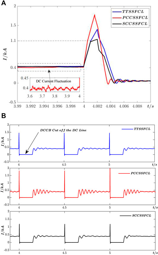
FIGURE 7. Waveforms of the DC current of the three SSFCLs. (A) Waveforms of the DC current when the fault occurs at 4.0 s. (B) Waveforms of the DC current under three repetitive short-circuit faults.
The waveforms of the fault current flowing through three self-powered FCLs are shown in Figure 8A. The SCCSSFCL can more sharply limit the increasing of the fault current as shown in Figure 7. After a short-circuit fault appears at 4.0 s, the current I3 can be induced by mutual inductance between inductors L1, L2 and inductor L3 in SPSSs. From 4.0 to 4.001 s, the current
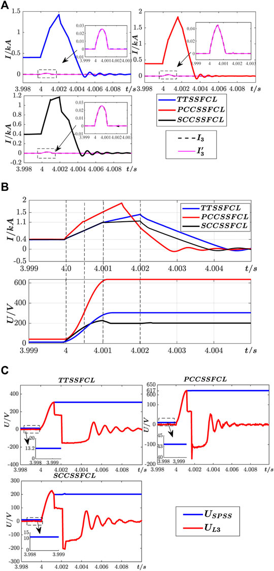
FIGURE 8. Power acquisition process of the SPSSs. (A) Current waveforms of the three SSFCLs. (B) SPSS voltage acquisition process. (C) SPSS voltage of the three self-powered SSFCLs.
A single IGBT can be driven by a voltage of 10–15 V or a several mA current. And a single IGBT can withstand 6.5 kV/3 kA at most. In this section, the switch in each FCL is composed of 2∼4 serial-connected IGBTs because the whole system voltage is less than 20 kV. Thus, the voltage obtained by the SPSS is sufficient to drive each IGBT, as shown in Figure 8B and Figure 8C. The CPU circuit can be controlled by the operation staff or operation computer, and the CPU circuit consume the less power (less than 1 W), which means that the power supply of the CPU circuit can be neglected in this study. As shown in Figure 8, the power supplied by the SPSS covers the driving power requirement for the FCL control circuitry on the secondary side.
Voltage UL3 across inductor L3 of the SPSS can be induced by the mutual inductances M23 and M13 after a short-circuit fault begins to appear, as shown in Figure 8C. UL3 is an AC voltage and can be rectified into a DC voltage by the rectifier unit, as shown in Figure 8C. In the normal state, a DC current fluctuation appears in the DC line, as shown in Figure 7. The SPSSs of the three FCLs thus obtain energy through the mutual inductances M23 and M13, as shown in Figure 8C. Every single IGBT can be driven to turn on in the normal state. The SPSS component can reliably obtain energy under three repetitive transient faults, as shown in Figure 9.
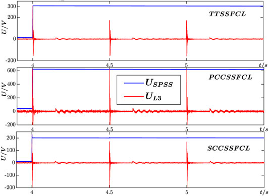
FIGURE 9. The power acquisition process of the SPSSs under three repetitive faults.
Conclusion
In this paper, three novel self-powered SSFCLs with SPSSs are developed and described. With the help of magnetic-coupling mutual inductance, the proposed SPSSs directly obtain energy from the DC fault lines in the fault state, Thus, the cost and complexity of the installation of extra voltage source equipment is minimized.
Simulation results in PSCAD/EMTDC are provided to confirm the current limit and power-acquisition capabilities of the proposed SSFCLs with SPSSs. In the normal state, the proposed SSFCLs take power from the DC line if the DC current fluctuation appears. This power is used to drive the operation of the IGBTs. During the fault state, the self-powered FCLs limit the short-circuit fault currents and reliably acquire energy to drive the power electronic switches. The SCCSSFCL substantially changes the fault current among the three structures. The proposed SPSSs thus solve the power supply problem of power electronic switches in FCLs. Moreover, this design method is not limited to applications in SSFCLs; that is, it can also be applied to other power supplies. The proposed self-powered SSFCLs can be applied in higher voltage DC grids by designing appropriate parameters.
Data Availability Statement
The original contributions presented in the study are included in the article/Supplementary Material, further inquiries can be directed to the corresponding author.
Author Contributions
JX and GL contributed to the conception and design of the study. JX and HZ organized case studies. LG wrote the first draft of the manuscript. All authors contributed to manuscript revision, read, and approved the submitted version.
Conflict of Interest
The authors declare that the research was conducted in the absence of any commercial or financial relationships that could be construed as a potential conflict of interest.
Publisher’s Note
All claims expressed in this article are solely those of the authors and do not necessarily represent those of their affiliated organizations, or those of the publisher, the editors and the reviewers. Any product that may be evaluated in this article, or claim that may be made by its manufacturer, is not guaranteed or endorsed by the publisher.
References
Dondi, D., Bertacchini, A., Brunelli, D., Larcher, L., and Benini, L. (2008). Modeling and Optimization of a Solar Energy Harvester System for Self-Powered Wireless Sensor Networks. IEEE Trans. Ind. Electron. 55 (7), 2759–2766. doi:10.1109/tie.2008.924449
Flourentzou, N., Agelidis, V. G., and Demetriades, G. D. (2009). VSC-based HVDC Power Transmission Systems: An Overview. IEEE Trans. Power Electron. 24 (3-4), 592–602. doi:10.1109/tpel.2008.2008441
Fu, M., Zhang, D., and Li, T. (2017). A Novel Coupling Method of Power Supplies with High Power Density, Efficiency, and Fast Dynamic Response for Spacecraft Hollow Cathode Power Supply Applications. IEEE Trans. Power Electron. 32 (7), 5377–5387. doi:10.1109/tpel.2016.2610442
Hafner, J. (2011). “Proactive Hybrid HVDC Breakers – a Key Innovation for Reliable HVDC Grids,” in Proc. CIGRE Bologna Symp., Bologna, Italy, January 2011, 1–8.
Heidary, A., Radmanesh, H., Rouzbehi, K., and Pou, J. (2019). A DC-Reactor-Based Solid-State Fault Current Limiter for HVdc Applications. IEEE Trans. Power Deliv. 34 (2), 720–728. doi:10.1109/tpwrd.2019.2894521
Hyo-Sang Choi, C., Byung-Ik Jung, J., and Yong-Sung Cho, C. (2009). Transient Characteristics of a Flux-Coupling Type Superconducting Fault Current Limiter According to Winding Direction. IEEE Trans. Appl. Supercond. 19 (3), 1827–1830. doi:10.1109/tasc.2009.2017836
Jalilian, A., Naderi, S. B., Negnevitsky, M., Tarafdar Hagh, M., and Muttaqi, K. M. (2017). Controllable DC‐link Fault Current Limiter Augmentation with DC Chopper to Improve Fault Ride‐through of DFIG. IET Renew. Power Generation 11 (2), 313–324. doi:10.1049/iet-rpg.2016.0146
Jalilian, A., Tarafdar Hagh, M., Abapour, M., and Muttaqi, K. M. (2015). DC-link Fault Current Limiter-Based Fault Ride-Through Scheme for Inverter-Based Distributed Generation. IET Renew. Power Gen. 9 (6), 1–10. doi:10.1049/iet-rpg.2014.0289
Kobayashi, K., Matsuo, H., and Sekine, Y. (2006). Novel Solar-Cell Power Supply System Using a Multiple-Input DC-DC Converter. IEEE Trans. Ind. Electron. 53 (1), 281–286. doi:10.1109/tie.2005.862250
Li, J., Zhao, B., Song, Q., Huang, Y., and Liu, W. (2016). Minimum Voltage Tracking Balance Control Based on Switched Resistor for Modular Cascaded Converter in MVDC Distribution Grid. IEEE Trans. Ind. Electron. 63 (9), 5437–5441. doi:10.1109/tie.2016.2586755
Li, Y., Lyu, X., and Cao, D. (2015). “A High Voltage Gain Modular Multilevel Dc–Dc Converter,” in 2015 IEEE Energy Conversion Congress and Exposition (ECCE), Montreal, Quebec, Canada, 20-24 Sept. 2015, 3535–3541.
Lim, S.-H., Han, T.-H., Yim, S.-W., Choi, H.-S., and Han, B.-S. (2007). Current Limiting Characteristics of a Flux-Lock Type SFCL Dependent on Fault Angles and Core Saturation. IEEE Trans. Appl. Supercond. 17 (2), 1827–1830. doi:10.1109/tasc.2007.899868
Lin Du, D., Caisheng Wang, W., Xianzhi Li, L., Lijun Yang, Y., Yan Mi, M., and Caixin Sun, S. (2010). A Novel Power Supply of Online Monitoring Systems for Power Transmission Lines. IEEE Trans. Ind. Electron. 57 (8), 2889–2895. doi:10.1109/tie.2009.2037104
Liu, G., Xu, Z., Xue, Y., and Tang, G. (2015). Optimized Control Strategy Based on Dynamic Redundancy for the Modular Multilevel Converter. IEEE Trans. Power Electron. 30 (1), 339–348. doi:10.1109/tpel.2014.2305663
Liu, J., Tai, N., Fan, C., and Chen, S. (2017). A Hybrid Current-Limiting Circuit for DC Line Fault in Multiterminal VSC-HVDC System. IEEE Trans. Ind. Electron. 64 (7), 5595–5607. doi:10.1109/tie.2017.2677311
Lyu, J., Zhang, X., Cai, X., and Molinas, M. (2019). Harmonic State-Space Based Small-Signal Impedance Modeling of a Modular Multilevel Converter with Consideration of Internal Harmonic Dynamics. IEEE Trans. Power Electron. 34 (3), 2134–2148. doi:10.1109/tpel.2018.2842682
Miao, Z., Sabui, G., Chen, A., Li, Y., Shen, Z. J., Wang, J., et al. (2015). “A Self-Powered Ultra-Fast DC Solid State Circuit Breaker Using a Normally-On SiC JFET,” in 2015 IEEE Applied Power Electronics Conf. Exposition (APEC), Charlotte, NC, March 15-19 2015, 767–773. doi:10.1109/apec.2015.7104436
Nie, Z., Yu, Z., Gan, Z., Qu, L., Huang, Y., and Zhao, B. (2021). Topology Modeling and Design of a Novel Magnetic Coupling Fault Current Limiter for VSC DC Grids. IEEE Trans. Power Electron. 36 (4), 4029–4041. doi:10.1109/tpel.2020.3025461
Qingrui Tu, Q., Lie Xu, Z., and Xu, L. (2011). Reduced Switching-Frequency Modulation and Circulating Current Suppression for Modular Multilevel Converters. IEEE Trans. Power Deliv. 26 (3), 2009–2017. doi:10.1109/tpwrd.2011.2115258
Radmanesh, H., Fathi, H., and Gharehpetian, G. B. (2015). Series Transformer-Based Solid State Fault Current Limiter. IEEE Trans. Smart Grid 6 (4), 1983–1991. doi:10.1109/tsg.2015.2398365
Sun, J., Du, J., Li, Y., Mo, S., Cai, Y., Yuan, W., et al. (2020). Design and Performance Test of a 20-kV DC Superconducting Fault Current Limiter. IEEE Trans. Appl. Superconductivity 30 (2), 5600305. doi:10.1109/TASC.2019.2963410
Urciuoli, D., and Veliadis, V. (2011). Demonstration of a 600-V, 60-A, Bidirectional Silicon Carbide Solid-State Circuit Breaker. Proc. Apec, Mar. 6, 354–358. doi:10.1109/apec.2011.5744620
Wu, Y., He, H., Rong, M., Murphy, A. B., Liu, Y., Niu, C., et al. (2011). The Development of the Arc in a Liquid Metal Current Limiter. IEEE Trans. Plasma Sci. 39 (11), 2864–2865. doi:10.1109/tps.2011.2158008
Wu, Z., Wen, Y., and Li, P. (2013). A Power Supply of Self-Powered Online Monitoring Systems for Power Cords. IEEE Trans. Energ. Convers. 28 (4), 921–928. doi:10.1109/tec.2013.2281075
Xu, J., Zhang, H., and Liu, H. (2018a). Current Limiter and Device Applied to Flexible Direct-Current Power Transmission System. Chinese Patent, CN108390363A
Xu, J., Zhang, H., and Liu, H. (2018b). Online Power-Taking Circuit and System of DC Power Transmission System Current Limiter. Chinese Patent, CN108599280B
Xu, Z., Xiao, H., Zhang, Z., Xue, Y., Liu, G., Tang, G., et al. (2017). Flexible HVDC Transmission System [M]. Beijing, China: China Machine Press, 68–78. (in Chinese).
Yang, Z., He, H., Yang, F., Wu, Y., Rong, M., Zhao, P., et al. (2019). A Novel Topology of a Liquid Metal Current Limiter for MVDC Network Applications. IEEE Trans. Power Deliv. 34 (2), 661–670. doi:10.1109/tpwrd.2019.2892501
Zhang, K., Zhou, B., Or, S. W., Li, C., Chung, C. Y., and Voropai, N. I. (2021). Optimal Coordinated Control of Multi-Renewable-To-Hydrogen Production System for Hydrogen Fueling Stations. IEEE Trans. Ind. Applicat., 1. doi:10.1109/TIA.2021.3093841
Zhang, L., Shi, J., Wang, Z., Tang, Y., Yang, Z., Ren, L., et al. (2017). Application of a Novel Superconducting Fault Current Limiter in a VSC-HVDC System. IEEE Trans. Appl. Supercond. 27 (4), 1–6. doi:10.1109/tasc.2017.2656634
Zhang, X., Li, H., Brothers, J. A., Fu, L., Perales, M., Wu, J., et al. (2016). A Gate Drive with Power Over Fiber-Based Isolated Power Supply and Comprehensive Protection Functions for 15-kV SiC MOSFET. IEEE J. Emerg. Sel. Top. Power Electron. 4 (3), 946–955. doi:10.1109/jestpe.2016.2586107
Zhang, X., Yu, Z., Zeng, R., Zhang, M., Zhang, Y., Xiao, F., et al. (2020). HV Isolated Power Supply System for Complex Multiple Electrical Potential Equipment in 500 kV Hybrid DC Breaker. High Voltage 5 (4), 425–433. doi:10.1049/hve.2019.0260
Keywords: fault current limiters, VSC DC grids, self-powered supply, mutual inductance coil, solid-state FCLs
Citation: Xu J, Gao L and Zhang H (2021) Design of Self-Powered Solid-State Fault Current Limiters for VSC DC Grids. Front. Energy Res. 9:760105. doi: 10.3389/fenrg.2021.760105
Received: 17 August 2021; Accepted: 13 September 2021;
Published: 23 September 2021.
Edited by:
Bin Zhou, Hunan University, ChinaReviewed by:
Zipan Nie, Institute of Electrical Engineering (CAS), ChinaAmin Jalilian, University of Wollongong, Australia
Copyright © 2021 Xu, Gao and Zhang. This is an open-access article distributed under the terms of the Creative Commons Attribution License (CC BY). The use, distribution or reproduction in other forums is permitted, provided the original author(s) and the copyright owner(s) are credited and that the original publication in this journal is cited, in accordance with accepted academic practice. No use, distribution or reproduction is permitted which does not comply with these terms.
*Correspondence: Lei Gao, Z2FvbGVpQG5jZXB1LmVkdS5jbg==