 Sooyoung Choi1
 Wonkyeong Kim
 Deokjung Lee
- 1Department of Nuclear Engineering and Radiological Sciences, University of Michigan, Ann Arbor, MI, United States
- 2Department of Nuclear Engineering, Ulsan National Institute of Science and Technology, Ulsan, South Korea
The pin-based pointwise energy slowing-down method (PSM), which is a resonance self-shielding method, has been refined to treat the nonuniformity of material compositions and temperature profile in the fuel pellet by calculating the exact collision probability in the radially subdivided fuel pellet under the isolated system. The PSM has generated the collision probability table before solving the pointwise energy slowing-down equation. It is not exact if the fuel pellet has nonuniform material compositions or temperature profile in all the subdivided regions. In the refined PSM-CPM, the pre-generated table is not required for directly calculating the collision probability in all the subdivided regions of the fuel pellet while solving the slowing-down equation. There are an advantage and a disadvantage to the method. The advantage is to exactly consider the nonuniformity of the material compositions and temperature profile in the fuel pellet. The disadvantage is the longer computing time than that of the PSM when the fuel pellet has more than five subdivided regions. However, in the practical use for UO2 pin-cells, it is still comparable for the computation time with the PSM and the conventional equivalence theory methods. In this article, using simple light water reactor 17 × 17 F A problems with a uniform material composition and temperature profile, it is demonstrated that PSMs (PSM and PSM-CPM) exhibit consistent accuracy in calculating the multiplication factor and the pin power distribution with no compromise in the computation time. More detailed accuracy assessments with various test cases, including problems representing the nonuniformity, are presented in the accompanying article.
1 Introduction
In reactor physics, all calculations are conducted with cross sections (XSs). The actual XSs for nuclides describe the very detailed energy resolution. XS data are composed of hundreds of thousands of energy points for major resonant nuclides (e.g., 238U). Even with modern computing resources, it is still time consuming and impractical to directly utilize raw XS data in lattice physics calculations. Because of this, XSs, especially in the resonance energy range that requires high-energy resolution, must be condensed during neutron transport computations. A resonance self-shielding calculation (or resonance treatment) is performed to condense a detailed XS into the multigroup level (e.g., ∼100 groups). Therefore, if the resonance self-shielding calculation is not accurate, all the subsequent calculations would not be meaningful. The resonance treatment is one of the most difficult and challenging parts of reactor physics.
The equivalence theory has been widely used for resonance treatment (Knott et al., 2010; Stamm’ler and Abbate, 1983). The equivalence theory gives a reasonable solution within a short computation time. Owing to this advantage, many lattice physics codes adopt the equivalence theory to generate effective multigroup XSs (Powney and Hutton, 2002; Rhodes et al., 2006). There has been much research into the equivalence theory to improve the accuracy of effective multigroup XSs and the applicability to general geometry (Koike et al., 2012; Godfrey, 2014; Choi et al., 2015a). However, there are still many points missing from the resonance calculation. The author’s previous works have determined that resonance scattering causes the overestimation of the 238U effective XS (Choi, 2017; Choi et al., 2017).
In one of the authors’ previous work (Choi et al., 2017), a new resonance self-shielding method, the pin-based pointwise slowing-down method (PSM), was developed to resolve limitations, that is, the overestimation of 238U XS due to resonance scattering sources, in the conventional equivalence theory. However, the PSM has an assumption for treating with the total XSs in the subdivided regions of the fuel pellet. As one of the techniques for achieving high performance, the PSM generates the collision probability of the isolated fuel pellet before solving the pointwise slowing-down equation. The collision probability is generated with the grid of the total XSs that is assumed to be constant in the subdivided regions of the fuel pellet. With the nonuniform material and temperature distribution, the total XSs in the subdivided regions are different from each other so that the accuracy of the effective XSs is impeded by the constant total XS assumption (Zhang et al., 2018; Zhang et al., 2020). Therefore, generating the collision probability during solving the slowing-down equation on the fly, a more rigorous method, PSM-CPM, has been developed to treat nonuniform material and temperature distributions in the fuel pellet.
This work reviews the PSM in brief and introduces PSM-CPM with the refinement. The work demonstrates the accuracy of the PSM and PSM-CPM with several light water reactor problems with only uniform material and temperature distributions. The computing time for the two methods is also estimated and compared. Detailed verifications of the PSM-CPM are performed with various light water reactor (LWR) problems with a nonuniform material composition and temperature profile, and the detailed XS comparison is presented to show the superior accuracy of the method in the accompanying article (Kim et al., 2021).
2 Pin-Based Pointwise Energy Slowing-Down Methods (PSMs)
The achievements of the PSM are summarized as follows: RI or XS look-up tables are not required for resonance treatment; the distribution of the scattering sources in the fuel pellet is accurately modeled; and PSMs have a comparable computational cost with the equivalence theory.
The neutron transport equation can be expressed with the radially subdivided regions (Stoker and Weiss, 1996) and collision probabilities for the two-region problem (i.e., fuel and moderator) in the resonance energy range as follows:
where
Using the lethargy form and the reciprocity relation, Eq. 1 is written as follows:
The flux of the subdivided region
In Eq. 3, the index
The transport equation for the nonfuel region is written as follows:
where
The flux of the nonfuel region
If
The PSM and PSM-CPM calculate the collision probability with a two-step approach. In the first step, the collision probabilities of the subdivided regions in the isolated fuel pellet are calculated.
The difference between PSM and PSM-CPM is the way to calculate
In the PSM, however,
Equation 7 is only exact if the fuel pellet has a constant material composition and temperature profile in all the subdivided regions. However, if the fuel is burned, the material compositions in the subdivided regions change differently from each other. For the burned fuel pellet, the burnup of the outermost subregion is higher than that in the inner subregion because of the spatial self-shielding effect. In addition, the thermal–hydraulic (TH) calculation is coupled with neutronics to analyze the power reactor. The fuel pellet must be divided into several rings to model the temperature profile from TH feedback. With the TH feedback, the temperature in the inner region is higher than that in the outer region. Obviously, the pointwise energy XSs depend on the material composition and the temperature. With nonuniform material compositions and temperatures, the total XSs of the subdivided regions are different from each other. In this case, an average total XS (i.e.,
where energy
Introducing the
In PSMs, the shadowing correction factor is calculated with two escape probabilities. One is the fuel escape probability of an isolated fuel pin, and the other is that of the fuel pin in the lattice (or core). Carlvik’s two-term rational approximation (Knott et al., 2010) is applied for a cylindrical geometry to calculate
where
where
It should be noted that
The shadowing effect correction factor, which adjusts the fuel escape probability of an isolated fuel pin to consider the shadowing effect, is defined as a ratio of the fuel escape probabilities of two systems in the isolated fuel pellet and the lattice as follows:
The shadowing effect correction factor is multiplied by the fuel escape probability in each subregion of the fuel pellets as follows:
where
It is assumed that the shadowing effect correction factor of the subdivided region
The collision probabilities from the nonfuel region are expressed as follows:
Finally, all the collision probabilities and escape probabilities, which are needed to solve the slowing-down equations in Eqs 4–6, are derived.
2.1 Calculation Flow
There are two different options depending on how the collision probabilities of the subdivided regions of the isolated fuel pellet (i.e.,
1. Read input information in a given problem.
2. Read the 72-group multigroup XS library and the 5⋅104 equal-lethargy pointwise energy XS library.
3. Generate the
4. Perform the fixed-source MOC transport calculation for the whole-problem domain, and then calculate the individual Dancoff factors of the fuel pins with the enhanced neutron current method (Yamamoto, 2012).
5. Calculate
6. Interpolate
7. Correct the shadowing effect using the shadowing effect correction factor as in Eq. 13, and then calculate
8. Solve the pointwise energy slowing-down equations in Eqs 4–6. Repeat steps 6–8 for all the pointwise energy points from high to low energy.
9. Condense the pointwise XS to the position-dependent multigroup XS. Consider the resonance upscattering effect for 238U (Choi, 2017; Choi et al., 2017). Return to step 5) until all the fuel pins in the problem are treated.
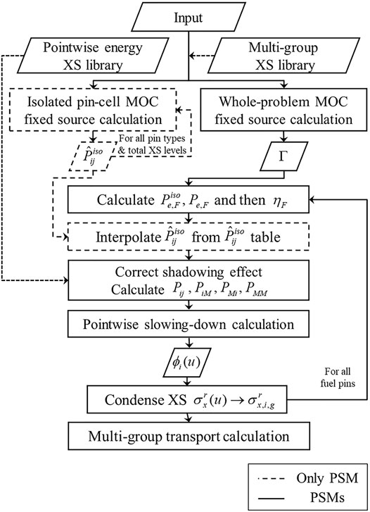
FIGURE 1. Flowchart of the pin-based pointwise energy slowing-down solution method (PSM) (Choi, 2017; Choi et al., 2017).
3 Numerical Results
Several LWR problems are solved to verify the accuracy of the PSMs. Table 1 presents a summary of test cases and methods used in the verifications. The test cases include the pin-cell and FA geometry with uniform material distribution, uniform temperature profile, and fresh fuel. The methods used in the comparisons are as follows:
1. EQ: The conventional equivalence theory.
2. PSM: The pin-based pointwise slowing-down method with the
3. PSM-CPM: The pin-based pointwise slowing-down method with the CPM.

TABLE 1. Summary of test cases (Choi, 2017).
The following option was used in all the calculations in Sensitivity Test for Energy Points in the Pointwise Cross-Section Library and VERA 17 × 17 Fuel Assembly Problem: MOC condition: 0.01 cm ray spacing, 128 azimuthal angles, and T–Y optimized three polar angles (Yamamoto et al., 2007). It should be also noted that those calculation results in Sensitivity Test for Energy Points in the Pointwise Cross-Section Library and VERA 17 × 17 Fuel Assembly Problem were calculated with the P2 high-order scattering model to reduce errors from the anisotropic source. The reference was the MCS Monte Carlo code (Lee et al., 2020). The numerical test was performed with the lattice physics code STREAM (Choi et al., 2015b). STREAM uses the method of characteristics (MOC) for the transport calculation and the equivalence theory for resonance treatment.
3.1 Sensitivity Test for Energy Points in the Pointwise Cross-Section Library
Sensitivity test was performed to determine a reliable option to give accurate results by PSMs. The parameter to test is the number of energy points in the PW XS libraries.
The number of energy points is important in terms of accuracy and computational efficiency. When many energy points are used, the solution from the slowing-down calculation is accurate. However, the calculation time is proportional to the number of energy points. Four pointwise energy libraries, which have different numbers of energy points, were used in the sensitivity test. A normal UO2 pin-cell depletion problem was solved with PSMs. The reason that the depletion problem was selected is that light nuclides usually do not need many energy points, whereas heavy nuclides need many energy points because of their many resonances in XSs. Pointwise energy XS libraries with 5,000, 10,000, 50,000, and 100,000 points were used in the test. The energy between 0.3 eV and 30 keV was divided with equal lethargy depending on the libraries. The result with 100,000 points was set as a reference. From the internal test, it was verified that more than 100,000 points do not have noticeable effect on the results.
Figure 2 shows the results with the four libraries. The result with 50,000 energy points is quite close to the reference. The differences in the eigenvalue are less than 5 pcm over all the depletion steps. The result with 10,000 energy points is also reliable in terms of the eigenvalue. The maximum difference is 17 pcm. However, the result with 5,000 energy points is significantly different from the reference, with a maximum difference of 133 pcm. From this sensitivity test for the number of energy points, it is verified that 50,000 energy points are sufficient to get an accurate result. In the STREAM code, the pointwise energy XS library with 10,000 points is used as a default. The library is accurate enough to get reasonable solutions for practical use. The library with 50,000 points is used as an option when a user wants to get the most accurate result. All the results in this work were generated with 50,000 energy points to get the highest accuracy. The number of energy points can be further reduced by using a small lethargy width for high energy and a large lethargy width for low energy because resonances at high energy are narrower and more densely distributed.
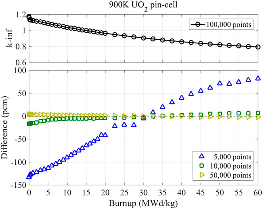
FIGURE 2. Comparison of k-inf from the PSM with different numbers of energy points in the XS libraries (Choi, 2017).
The calculation times elapsed in PSMs were tested. A UO2 fuel burnup level of 60 MW d/kg was used in this test. The number of the subdivided regions of the pellet is 5. Because of the spatial self-shielding effect in the fuel pellet, the material compositions are nonuniform in the pellet. The number of nuclides in the fuel is 198. The library with 50,000 points was used in this test. The eigenvalue results and elapsed time are shown in Table 2.
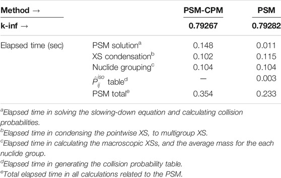
TABLE 2. Elapsed time in resonance treatment with PSMs (Choi, 2017).
When the
3.2 VERA 17 × 17 Fuel Assembly Problem
17 × 17 fuel assembly (FA) problems were solved to verify PSMs. The 17 × 17 FAs in the VERA benchmark problem (Godfrey, 2014) were selected and solved as described in this section. Figure 3 shows the configuration of the rods for various types of FAs. Various burnable poisons and control rods were used in the FA design. Table 3 summarizes the material information and short descriptions of the FAs. The detailed specifications of the geometry and the material compositions are well described in the reference (Godfrey, 2014). The solutions for the 17 × 17 FAs were generated by the PSM. The fuel pellets used in this problem have a uniform material composition and a uniform temperature profile.
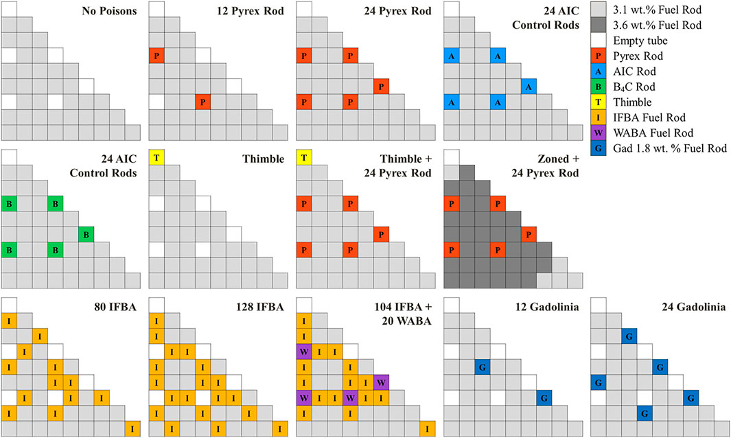
FIGURE 3. Configuration of rods in the 17 × 17 fuel assembly problem (Choi, 2017).
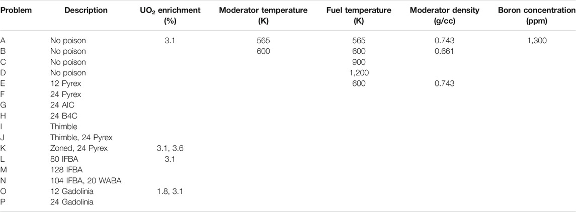
TABLE 3. Description for the fuel assembly problem (Choi, 2017).
The results for k-inf and the pin power distribution were obtained with PSMs as shown in Table 4 and Table 5, respectively. PSMs show quite accurate and consistent results. The differences in k-inf are of the order of 100 pcm. For the FA with AIC control rods, the PSM-CPM has a difference of 216 pcm in k-inf. The RMS difference and the maximum difference in the power distribution are approximately 0.17 and 0.41%, respectively.

TABLE 4. k-inf results—PSM and PSM-CPM.
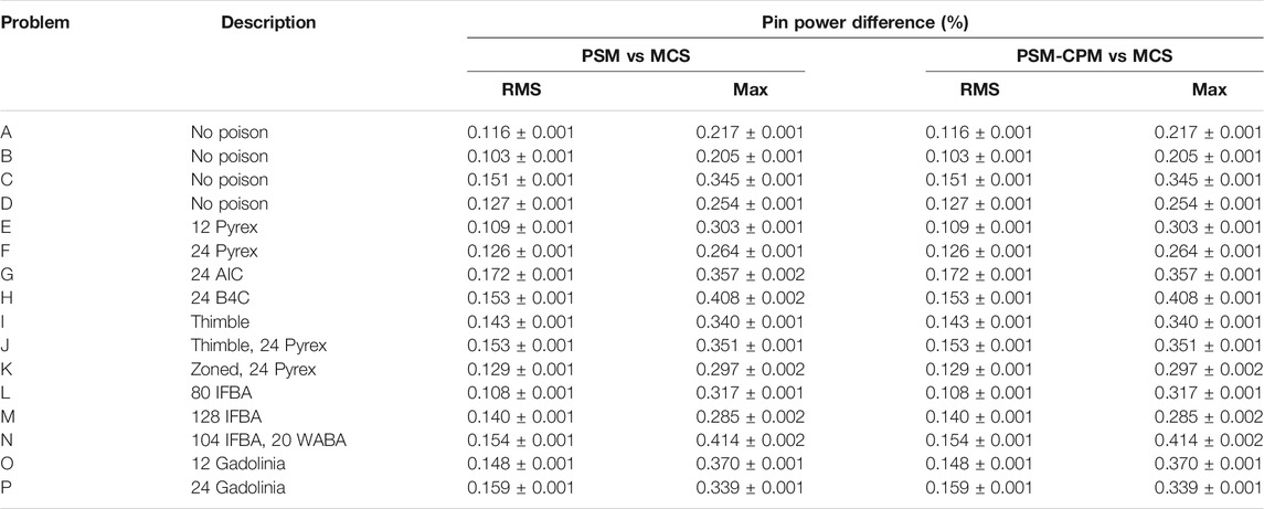
TABLE 5. Pin power distribution results—PSM and PSM-CPM.
From the verification with the various types of 17 × 17 FAs, it is verified that PSMs calculate accurate and consistent results in k-inf and the pin power distribution.
The PSM and PSM-CPM calculate identical solutions for the condition (i.e., a uniform material composition and temperature profile in the fuel pellet). There is a slight difference (i.e., less than 3 pcm in the eigenvalue) between PSM and PSM-CPM caused by the
3.3 Test for Computing Time
The PSM and PSM-CPM showed high accuracy in the reactor parameters for the various verification problems. In order to use the PSM and PSM-CPM in a practical design, it should be confirmed that they calculate the effective multigroup XS within a reasonable computation time.
The 17 × 17 FA problem was selected for the computation time comparison. The EQ was compared to the PSM. The FA was modeled with octant symmetry. For this section, the following option was used in the calculation: MOC condition: 0.05 cm ray spacing, 48 azimuthal angles, and three polar angles. In the test, each pin-cell had eight azimuthal sectors, three radial subregions in the coolant, and five radial subregions in the fuel pellet. The number of flat source regions is 2,842. The number of macroscopic XS sets is 242. The inflow transport corrected P0 (TCP0) model is used for both options (Choi et al., 2015c). Generally, these MOC conditions and the TCP0 model are used for practical calculations.
The time comparison results are shown in Table 6. The results were generated on an OSX system with a 3.1-GHz Intel Core i7 processor. PSMs perform the energy-independent fixed-source calculations to consider the shadowing effect. However, the EQ needs 15 fixed-source solutions for the fuel. The STREAM code performs the fixed-source MOC calculation for the resonance energy groups above 4 eV (Choi et al., 2015a). In case of the 17 × 17 FA problem, the Dancoff factors are calculated for the fuel and the cladding. PSMs are not applied on the resonance treatment for the cladding. Both PSMs and EQ use a common resonance treatment method (Choi et al., 2015a) for the cladding. The cladding resonance treatment method is based on the equivalence theory, and therefore PSMs and EQ perform energy-group–dependent MOC fixed-source calculations. Finally, PSM requires 16 MOC fixed-source solutions (1 for the fuel; 15 for the cladding), whereas EQ requires 30 fixed-source solutions (15 for the fuel; 15 for the cladding). This is why PSMs need approximately half the computation time in the fixed-source calculation (MOC FSP in Table 6) compared to EQ. Obviously, the elapsed time in the fixed-source MOC calculation depends on the MOC ray conditions. PSMs solve the slowing-down equations for the individual fuel pins. In the case of the 17 × 17 FA problem with octant symmetry, the slowing-down equations are solved for 39 fuel pins. Approximately 0.41 s is spent on the pointwise energy slowing-down calculations for all the fuel pins in the problem. PSMs spend additional time on grouping the nuclides and the energy condensations. A non-negligible time is consumed for these calculations, although the calculations are quite simple. Because the pointwise energy XS data are used in PSMs, these calculations are inevitable. The PSM-CPM takes a longer time in the slowing-down solver because it calculates the collision probability with the CPM solver for all energy points. PSMs spend less time in interpolating the RI from the multigroup RI library because they do not use the RI look-up table to calculate the effective XSs of fuel materials.
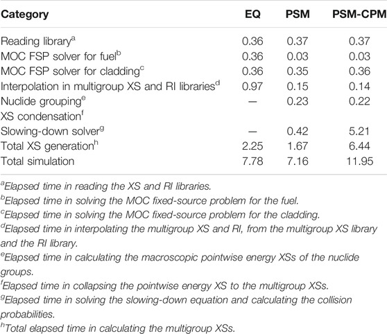
TABLE 6. Comparison for elapsed time (unit: s) (Choi, 2017).
The same problem was solved with different numbers of the radially subdivided regions in the fuel pellet. Figure 4 shows the calculation time as a function of the number of the subdivided regions in the fuel pellet. Both PSM and PSM-CPM were tested with different numbers of regions. When the number of radially subdivided regions is small, the differences in the calculation time between PSMs are not noticeable. As the number of the subdivided regions increases, the elapsed time used in the XS generation significantly increases with the PSM-CPM. With the PSM-CPM, the XS generation accounts for a very large portion of the total simulation. However, the elapsed time in the XS generation with the PSM is not very long compared to the total simulation time. The PSM is very effective in reducing the calculation time in the XS generation.
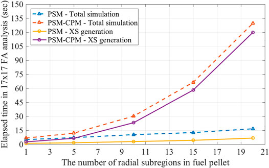
FIGURE 4. Elapsed time as a function of the number of radial meshes (Choi, 2017).
In conclusion, PSMs can calculate the multigroup XS within a reasonable computation time. PSMs save the calculation time by reducing the number of MOC fixed-source calculations. Even though PSMs solve the pointwise energy slowing-down equations, the calculation time is not problematic because various techniques are applied to enhance the performance of PSMs (Choi, 2017). The PSM-CPM takes a longer time in calculating the multigroup XSs with many subdivided regions in the fuel pellet. Nevertheless, the PSM-CPM is still useful because more than five subdivided regions are hardly used in the practical calculations for UO2 pin-cells. For a uniform material distribution and temperature profile, PSMs show consistent results. The comparative analysis between PSM and PSM-CPM for a nonuniform material distribution and temperature profile is presented in the accompanying article (Kim et al., 2021).
4 Conclusion
The PSM has been refined to exactly consider the collision probability in the subdivided regions of the isolated fuel pellet. The collision probabilities of an isolated pellet with the radial subdivisions are calculated by using the CPM. The PSM calculates the collision probability corresponding to the grid of the total XSs which is assumed to be constant in all the subdivided regions of the fuel pellet before solving the slowing-down equation. Then, the PSM uses a pre-generated look-up table for the collision probability to reduce the calculation time, but it is only valid if the fuel pellet has a uniform material composition and temperature profile in the subdivided regions of the fuel pellet. On the other hand, the PSM-CPM directly calculates the collision probability in the fuel pellet while solving the slowing-down equation so that exact collision probabilities in all the subdivided regions for the isolated fuel pellet are calculated.
The PSM-CPM has been verified with a few types of LWR FA. PSMs generate consistent results for specified problems in this article. The verification calculations showed good agreement in the eigenvalues, with differences of the order of 100 pcm compared to those of the reference solutions. The pin power distributions were also sufficiently accurate. It has also been demonstrated that the computation times using the PSM-CPM are comparable to those with the conventional equivalence theory methods in the practical use. The accompanying article demonstrates more comparative analysis to verify the PSM-CPM for nonuniform material and temperature distributions in the fuel pellet.
Data Availability Statement
The original contributions presented in the study are included in the article/Supplementary Material; further inquiries can be directed to the corresponding author.
Author Contributions
SC contributed to the conception and design of the methodology. SC wrote the first draft of the manuscript. SC and WK wrote sections of the manuscript. WK reviewed and edited the manuscript. DL supervised all the activity for the manuscript. All authors contributed to manuscript revision and read and approved the submitted version.
Funding
This work was supported by the National Research Foundation of Korea (NRF) grant funded by the government of Korea (MSIT) (No. NRF-2019M2D2A1A03058371). This work was partially supported by Korea Institute of Energy Technology Evaluation and Planning (KETEP) grant funded by the Korea government (MOTIE) (20206510100040).
Conflict of Interest
The authors declare that the research was conducted in the absence of any commercial or financial relationships that could be construed as a potential conflict of interest.
Publisher’s Note
All claims expressed in this article are solely those of the authors and do not necessarily represent those of their affiliated organizations, or those of the publisher, the editors, and the reviewers. Any product that may be evaluated in this article, or claim that may be made by its manufacturer, is not guaranteed or endorsed by the publisher.
References
Carlvik, I. (1964). A Method for Calculating Collision Probabilities in General Cylindrical Geometry and Applications to Flux Distributions and Dancoff Factors. Stockholm (Sweden): Aktiebolaget Atomenergi. A/CONF. 28/P/681.
Choi, S., Khassenov, A., and Lee, D. (2015). Resonance Self-Shielding Method Using Resonance Interference Factor Library for Practical Lattice Physics Computations of LWRs. J. Nucl. Sci. Technol. 53, 1142–1154. doi:10.1080/00223131.2015.1095686
Choi, S., Lee, H., Hong, S. G., and Lee, D. (2015). Resonance Self-Shielding Methodology of New Neutron Transport Code Stream. J. Nucl. Sci. Technol. 52, 1133–1150. doi:10.1080/00223131.2014.993738
Choi, S., Smith, K., Lee, H. C., and Lee, D. (2015). Impact of Inflow Transport Approximation on Light Water Reactor Analysis. J. Comput. Phys. 299, 352–373. doi:10.1016/j.jcp.2015.07.005
Choi, S., Lee, C., and Lee, D. (2017). Resonance Treatment Using Pin-Based Pointwise Energy Slowing-Down Method. J. Comput. Phys. 330, 134–155. doi:10.1016/j.jcp.2016.11.007
Choi, S. (2017). Pin-Based Pointwise Energy Slowing-Down Method for Resonance Self-Shielding Calculation. Doctoral Thesis. Ulsan National Institute of Science and Technology.
Godfrey, A. T. (2014). VERA Core Physics Benchmark Progression Problem Specifications. Oak Ridge National Laboratory, Oak Ridge National Laboratory. CASL-U-2012-0131-004.
Kim, W., Choi, S., and Lee, D. (2021). Refinements of Pin-Based Pointwise Energy Slowing-Down Method for Resonance Self-Shielding Calculation-II: Verifications. Front. Energy Res. 9, 765865. doi:10.3389/fenrg.2021.765865
Knott, D., and Yamamoto, A. (2010). “Lattice Physics Computations,” in Handbook of Nuclear Engineering. Editor D.G. Cacuci (Boston, MA: Springer US), 913–1239. doi:10.1007/978-0-387-98149-9_9
Koike, H., Yamaji, K., Kirimura, K., Sato, D., Matsumoto, H., and Yamamoto, A. (2012). Advanced Resonance Self-Shielding Method for gray Resonance Treatment in Lattice Physics Code GALAXY. J. Nucl. Sci. Technol. 49, 725–747. doi:10.1080/00223131.2012.693885
Lee, H., Kim, W., Zhang, P., Lemaire, M., Khassenov, A., Yu, J., et al. (2020). MCS - A Monte Carlo Particle Transport Code for Large-Scale Power Reactor Analysis. Ann. Nucl. Energ. 139, 107276. doi:10.1016/j.anucene.2019.107276
Powney, D. J., and Hutton, J. L. (2002). The Next Generation WIMS Lattice Code : WIMS9. Seoul, Korea: PHYSOR-2002.
Rhodes, J., Smith, K., and Lee, D. (2006). CASMO-5 Development and Applications. Vancouver, BC, Canada: PHYSOR-2006.
Stamm'ler, R. J. J., and Abbate, M. J. (1983). Methods of Steady-State Reactor Physics in Nuclear Design. London: Academic Press.
Stoker, C. C., and Weiss, Z. J. (1996). Spatially Dependent Resonance Cross Sections in a Fuel Rod. Ann. Nucl. Energ. 23, 765–778. doi:10.1016/0306-4549(95)00074-7
Yamamoto, A., Tabuchi, M., Sugimura, N., Ushio, T., and Mori, M. (2007). Derivation of Optimum Polar Angle Quadrature Set for the Method of Characteristics Based on Approximation Error for the Bickley Function. J. Nucl. Sci. Technol. 44, 129–136. doi:10.1080/18811248.2007.9711266
Yamamoto, A. (2012). Evaluation of Background Cross Section for Heterogeneous and Complicated Geometry by the Enhanced Neutron Current Method. J. Nucl. Sci. Technol. 45, 1287–1292. doi:10.1080/18811248.2008.9711916
Zhang, Q., Jiang, R., Zhao, Q., Cao, L., and Wu, H. (2018). Accurate Resonance Absorption Calculation for Fuel Pins with Non-uniform Intra-pellet Temperature Profile Based on ultra-fine-group Slowing-Down Calculations. Ann. Nucl. Energ. 120, 392–401. doi:10.1016/j.anucene.2018.06.005
Keywords: resonance self-shielding calculation, equivalence theory, pointwise energy slowing-down method, resonance treatment, light water reactor, reactor physics
Citation: Choi S, Kim W and Lee D (2021) Refinements of the Pin-Based Pointwise Energy Slowing-Down Method for Resonance Self-Shielding Calculation—I: Theory. Front. Energy Res. 9:765863. doi: 10.3389/fenrg.2021.765863
Received: 27 August 2021; Accepted: 08 November 2021;
Published: 20 December 2021.
Edited by:
Ding She, Tsinghua University, ChinaReviewed by:
Qian Zhang, Harbin Engineering University, ChinaGuang Hu, Xi’an Jiaotong University, China
Copyright © 2021 Choi, Kim and Lee. This is an open-access article distributed under the terms of the Creative Commons Attribution License (CC BY). The use, distribution or reproduction in other forums is permitted, provided the original author(s) and the copyright owner(s) are credited and that the original publication in this journal is cited, in accordance with accepted academic practice. No use, distribution or reproduction is permitted which does not comply with these terms.
*Correspondence: Deokjung Lee, ZGVva2p1bmdAdW5pc3QuYWMua3I=