 S. Vijayakumar
 N. Sudhakar
- School of Electrical Engineering, Vellore Institute of Technology, Vellore, India
Transport is a vital sector for achieving sustainable development. The evolution of the electric vehicle is subject to the charging time, accessibility, and facility. On-board chargers are broadly used in the battery-electric and plug-in-electric fleets due to their easy installation and low cost. Also, it must be powerful and extremely efficient because of the constrained interior area and quick charging times. The minimization of hardware requirements and ease of interconnection problems are benefits of unidirectional charging. This review article presents an overview of charging levels, standards of chargers, and various topologies. On-board chargers pose a higher-power rating that reduces the anxiety of charging time and improves the charging facility on level-1 and level-2 grid supply. Unidirectional chargers reduce the charger size while other two-stage chargers pose a higher charging rate with various topologies. Finally, emerging charging trends in off-board charging, inductive charging, technology about vehicle-to-grid, wide-bandgap devices, and application of renewable energy uses are addressed.
Highlights
• The electric vehicle charger type and the charging level are reviewed.
• The single-stage and two-stage on-board electric vehicle chargers of different converter topologies are described and compared.
• Charging and safety standards are briefly explained as also the future charging trends.
• Various commercial on-board chargers are listed and compared.
1 Introduction
Global warming is a big crisis in climate change and is hazardous to the environment. One of the reasons for global warming is exhaust gas from the IC engine vehicle and the air pollution in transportation. Also, the fuel shortage for vehicles, price, and demand for fuel are of great concern (Wirasingha et al., 2008; Ahourai et al., 2013). Green vehicles are solar-powered, electric vehicles, fuel cell vehicles, and hybrid vehicles help to mitigate air pollution and global warming (Cheng et al., 2014). The electric vehicle is one of the significant technologies for fossil fuels to save the environment and achieve energy sustainability (Pan and Zhang, 2015).
An electric vehicle consists of a battery, a powerful electronic device, and an electric motor for the propulsion system. A battery charging device is the most important subsystem of an electric vehicle (Vankayalapati et al., 2018). Electric vehicle charging technologies are categorized into battery swapping methods, conductive charging, and inductive charging. Battery swapping technologies are replaced once in a particular driving range but it needs a specific place. In the battery swapping technology, TESLA can charge the battery in 90 s (Tesla unveils, 2013). Currently, China is the leading country in battery swapping points (Chen et al., 2012). In conductive charging, an electric vehicle is charged at the charging station by connecting the vehicle to the power supply through the cable. The conductive charger is divided into on-board and off-board chargers. An on-board charger is a device that is mounted in the vehicle for charging the battery when it is in an idle condition. By considering the limitations of space and weight in the electric vehicle, a high-efficiency DC–DC converter with low cost is suggested. An on-board charger accomplishes the needs and yields attention due to the deficiency of a fast-charging station (Haghbin et al., 2011; Kim and Kang, 2014). An on-board charger enables the vehicle to charge at home, parking area, and charging station (Patil et al., 2012). It can charge the battery with wide variations of the voltage on the state of charge of the battery.
An on-board charger is used in battery electric vehicles (BEV) and plug-in hybrid electric vehicles (PHEV) (Chae et al., 2010; Grenier et al., 2010). So, the on-board charger rating is 3–6 kW which belongs to a single-phase supply that is generally installed and it can be unidirectional or bidirectional (Gautam et al., 2012). This technology enables the EV to charge the battery from any available AC power source (Whitaker et al., 2014). A level-2 on-board charger needs an electric vehicle supply equipment device to provide a 240 V supply which is mounted on the wall (Li et al., 2014). On-board charger technology is also used in inductive power transfer while it acts as the receiver side and is mounted in the vehicle. Off-board charging is called fast charging, and it charges the vehicle in a few hours. In an off-board charging method, a DC–DC converter is placed in a charging station that provides DC power to the vehicles through cables (Tao et al., 2019). It is not limited in size and weight but it needs added cost for infrastructure to implement the number of charging station (Ghorbal et al., 2012). The fast-charging station is available with high EV mobility (Berjoza and Jurgena, 2015). Off-board chargers decrease the lifespan of battery life when compared to an on-board charger (Yilmaz and Krein, 2013). The grid to vehicle (G2V) and vehicle-to-grid (V2G) technologies are popular in electric vehicle charging that electric vehicle can charge the battery from the grid as well as discharge to the grid during peak demand on the grid by the bidirectional charger (Tuttle and Baldick, 2012). Battery chargers can make harmful harmonic effects such as low power quality, poor power factor, and voltage distortion on the grid system (Sul and Lee, 1995; Bojrup et al., 2002) but it is mitigated by an active front-end rectifier in the chargers (Masoum et al., 2010; Lee et al., 2011). The solar-powered electric vehicle has been intended by car manufacturers, such as Tesla, Audi, and Toyota, and a solar-powered EV developed by NEDO, Sharp, and Toyota companies has been publicly tested since July 2019.
2 On-board charger-based electric vehicles
Level-1 and level-2 charging standards use single phase and three phases of AC grid supply. Level-2 needs dedicated private and public facilities with dedicated equipment for home or public charging whereas level-1 did not need dedicated equipment. Level 3 is the DC charging method and it is used for commercial applications. Different power levels (Yilmaz and Krein, 2013; Jain and Kumar, 2018) of electric vehicle charging are shown in Table.1.
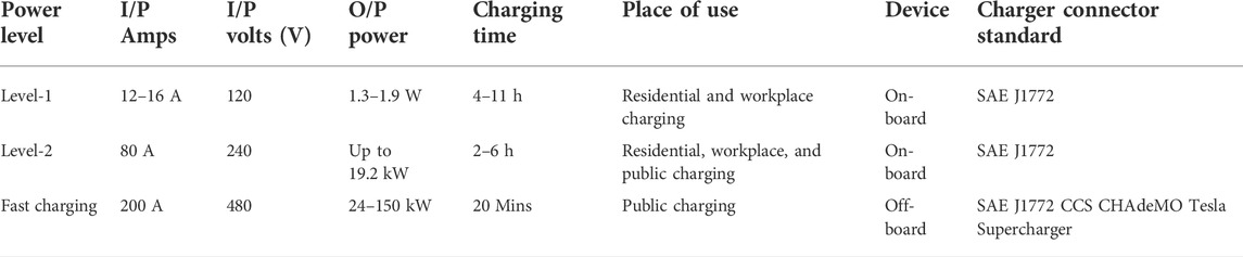
TABLE 1. Electric vehicle charging level.
The EV is classified into FCV, PHEV, and BEV in Figure 1, (Khaligh and Li, 2010). Among these, the BEV and PHEV are charged by the battery from the AC and DC outlets. A BEV may be an automobile or a truck that derives all motive force from the battery itself without the assistance of another engine. Such as a fuel cell or IC engine charging of the battery needs an external power source terminal (Dell et al., 2014). Typically, they can cover 100–250 km on a charge whereas top-tier models can go a lot further from 300 to 500 km (Grunditz and Thiringer, 2016). All of Tesla’s models are Nissan Leaf, Chevy Bolt, and Jaguar I-Pace.
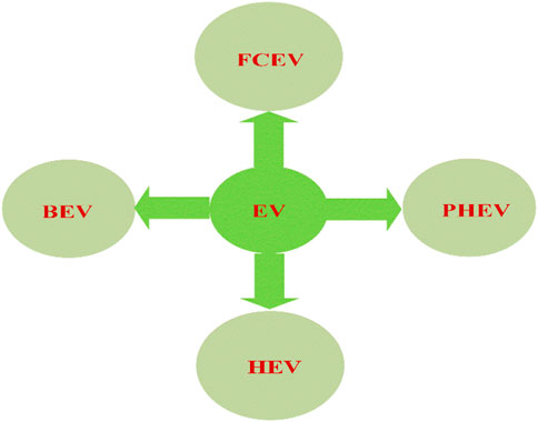
FIGURE 1. Classification of electric vehicles.
A plug-in hybrid electric vehicle, Figure 2, (Jain and Kumar, 2018), uses both an internal combustion engine (ICE) and an electrical power train such as an HEV. But the difference between them is that the PHEV uses electric propulsion as the main driving force, so this vehicle requires a bigger battery capacity than HEVs (Un-Noor et al., 2017). PHEVs offer higher fuel economy than HEVs and ICEVs, up to 133 miles per gallon of gasoline equivalent (Diaz, 2021). PHEV batteries can charge by plug-in at an AC outlet and by regenerative braking in an ICE engine (Blau, 1998). A plug-in hybrid electric car emits less than an average global ICE vehicle using gasoline on a life-cycle basis (IEA, 2019).
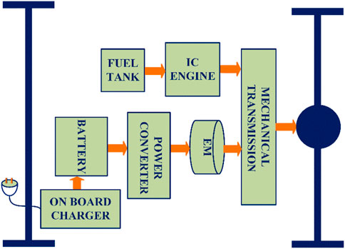
FIGURE 2. Plug-in hybrid electric vehicles (Ahourai et al., 2013).
3 Types of electric vehicle chargers
Electric vehicle chargers are categorized into the on-board charger, off-board chargers or fast chargers, and inductive chargers in Figure 3.
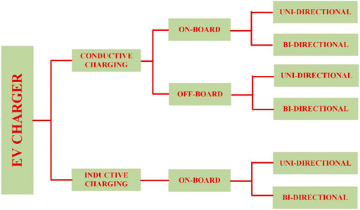
FIGURE 3. Classification of EV chargers.
3.1 On-board chargers
The OBC charger classifies into two stages, that is, topology and single-stage topology. The two-stage charger consists of a PFC rectifier to get a good power factor and a DC–-DC converter to control the output voltage and provide galvanic isolation (Choi et al., 2014; Lee and Chae, 2014; Wang et al., 2014). The on-board charger for AC supply is level-1 and level-2 as defined in SAE J1772 (Ucer et al., 2019). Level-1 and level-2 on-board chargers utilize the supply range of (120–240 V AC) and provide a high power of 1.9 and 19.2 kW (IEC 61851-23:2014, 2014) and this range of power supply is available in residential and public. When the OBC connects to a single-phase supply, a larger power oscillation at a double-line frequency (Li et al., 2013a) generates at the diode bridge rectifier, which would disappear when connecting to a three-phase power supply. The on-board charger should meet the harmonic regulations and standards of IEC 6100-3-2 and IEEE 519 for high-power quality (IEC 61000-3-2:2018+AMD1:2020, 2020).
3.1.1 Multifunctional on-board charger
A multifunctional single-phase on-board EV charger with a new unified control system supports the main functions of V2G/G2V and ancillary functions such as reactive power support, harmonic reduction, and voltage regulation simultaneously in a residential power system (Taghizadeh et al., 2018). In study of Taghizadeh et al. (2020), they proposed an on-board charger design for an EV that can charge the EV from another vehicle using the vehicle to vehicle charging method (Verma et al., 2020a). Solar PV is connected with grid to meet the domestic load, G2V, G2H in islanded mode, and V2G operation.
3.1.2 On-board integrated chargers
Integrated OBCs use driving circuit components such as the electric motor, and the inverter, for battery charging instead of a dedicated charging circuit with large passive components (Shi et al., 2017a). The motor windings are utilized as the propulsion inverter filters, galvanic isolation, and bidirectional DC/AC converter cum inverter. This technique has developed as an optimum dealing between on-board and off-board battery chargers. The efficacy of this technique includes various technical criteria, namely, limited and no winding reconfiguration with zero average torque and torque ripple production throughout the charging process. The aforementioned characteristics will be heavily influenced by the motor type, number of phases, and power converter used (Xiao et al., 2019).
3.2 Off-board charger
It delivers DC power to the EV battery through the cable from an isolated power converter located outside (Tu et al., 2019). Off-board chargers consist of two stages, the first stage is an AC–DC converter and the second stage is a DC–DC converter (Seth and Singh, 2021). Off-board charger offers more power than an on-board charger in the range of 50 kW (Celli et al., 2014). The SAE International has drafted the fast charger configurations with DC voltage of up to 600 V and a current of up to 550 A to charge EVs within the acceptable time (Tan et al., 2016a). The most popular converter topologies are Vienna rectifier (Channegowda et al., 2015), multilevel neutral point clamp chopper (Rivera et al., 2015), and interleaved converters (Abusara and Sharkh, 2013). The aforementioned converters can be made in either unidirectional topology (G2V) or bidirectional topology (G2V and V2G) (Chaurasiya and Singh, 2019). According to the study of Nachinarkiniyan and Subramanian (2020), solar PV enabled a fast-charging station, steadily charging the battery irrespective of the radiation.
3.3 Inductive chargers
An inductive charger is a choice for both on-board and off-board chargers in present days (Feng et al., 2020).The inductive charger works on electromagnetic induction between two coils kept nearby. Receiving coil produces the varying magnetic field that induces the power in the transmitting coil which charges the battery. To maximize the transferred energy, both coils should be near and well-aligned (Miller et al., 2015). IPT consists of a transmitter converter on the primary side, magnetic coupling coils, and a receiver converter on the secondary side with the on-board charger facility (Hasan et al., 2015; Shi et al., 2017b). Dynamic inductive charging is quickly becoming trending research on EV charging (Shin et al., 2014) and has been implemented in Nissan Magnite, Renault Kiger, and Hyundai Aura cars. Inductive chargers are categorized into three types that are microwave radiation, electric field couple, and magnetic field couple (Mayordomo et al., 2013; Sasaki et al., 2013; Dai and Ludois, 2015). It has advantages of safety, convenience, flexibility, weather immunity, and the possibility of range extensions (Wang et al., 2005; Khaligh and Dusmez, 2012).
3.4 Hybrid chargers
Charging the electric vehicle through the grid with a solar PV energy source is credible for battery charging and saving time (Guru Kumar et al., 2019). The algorithm is used to monitor the battery parameters with solar PV panels to ensure battery health and efficiency while charging under CC–CV (Padmagirisan and Sankaranarayanan, 2019). Inductive and PV combinedly charge the battery using a dual input boost converter (Kamalapathi et al., 2021). In the study of Kumaravel et al. (2019), dual input and dual output converters operate in multiple energy storage sources to charge the battery as well as power the grid.
4 On-board charger topologies
On-board chargers are classified into unidirectional and bidirectional chargers. The unidirectional chargers permit the G2V technology; bidirectional chargers support both the G2V and V2G technology. The on-board unidirectional EV charger block diagram is shown in Figure 4.

FIGURE 4. On-board charger block diagram.
4.1 Single-stage unidirectional chargers
The DC–DC converter followed by an AC–DC diode rectifier is called a single-stage charger and its details are shown in Table 2. The single-stage charger is used for the need of lower cost and in size (Lee et al., 2019). It permits the removal of huge components and costly components such as inductors and DC-link capacitors (Mishra et al., 2020) used in two-stage chargers. For the power factor correction, many diodes and active switches are needed and cause circuit complexity. But the single-stage charger is too simple and lower cost (Egan et al., 2007; Lu et al., 2008). The single-stage battery chargers with non-isolated converters are affected by a limited conversion ratio, which limits their application for the wide range of output voltage. The lower frequency component is generated by the rectification stage (Kim et al., 2016) and causes the larger magnetizing current in the high-frequency transformer. The single-stage battery charger is based on a diode-clamped series-resonant converter proposed in Yoon et al. (2013) and it achieves high power with a good power factor but low efficiency. The electrolytic capacitor-less in Jeong et al. (2016) overcomes the single-power-conversion OBC comprises a step-up AC–DC converter with an active-clamp circuit and a series-resonant circuit Figure 5. For power factor correction, an active-clamp circuit recycles the transformer stored energy. The series resonant circuit enables fast turn on and off time of the output diode and the output power level-1 (i.e.,) 350 V.
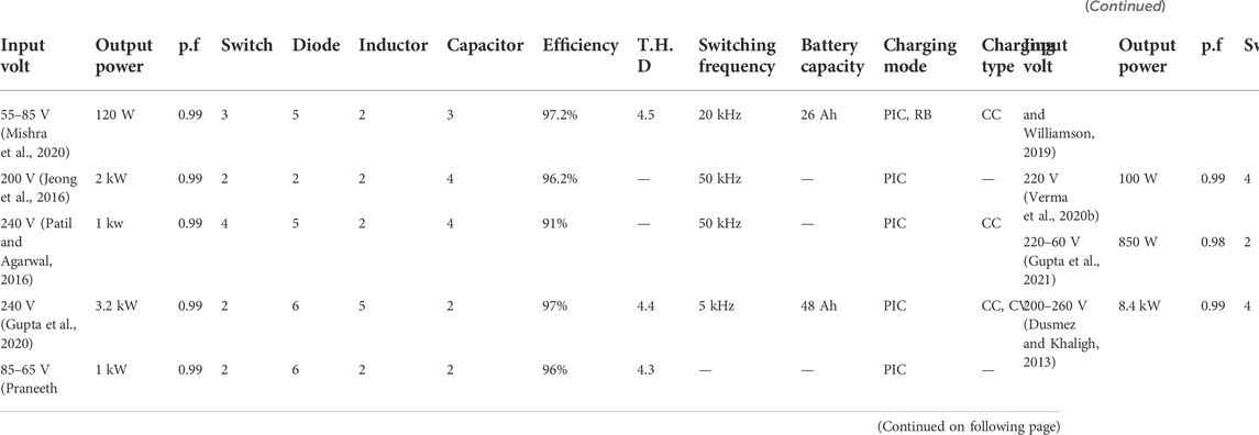
TABLE 2. Single-stage unidirectional converter summary.
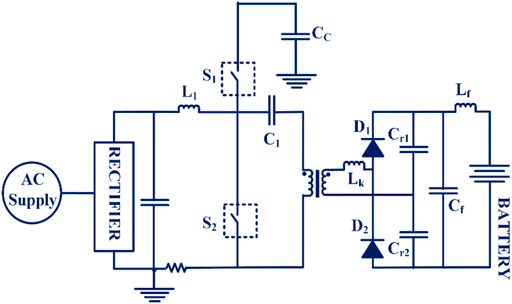
FIGURE 5. Single-stage resonant converter charger.
The single-stage non-isolated buck–boost charger Figure 6 is used for light electric vehicles to charge the battery from the grid supply during plug-in and regenerative braking. By using non-linear carrier control (NLCC) techniques, circuit size is reduced as well as feedback circuit complexity with the improvement of PFC at the gird side (Mishra et al., 2020). A single-stage resonant converter (Li et al., 2013b) transfers the input supply to the battery along with leakage inductance energy. Since charging a battery in a sinusoidal-like direct current (Youn and Lee, 2011; Yoo et al., 2013), input AC power goes to the battery side directly, without an energy buffer such as a DC-link capacitor. PFC is realized by keeping the switching frequency constant while switches obey zero current switching conditions. In this topology, a bulky inductor and DC-link capacitor are not used. A compensator proposed in Patil and Agarwal (2016) reduces the battery ripple current without bulk filter components and complicated control. A current ripple compensator, that is, CUK converter connects the series with the battery to reduce the battery ripple current. Boost and zeta converters are connected in a cascaded form, and a capacitor is connected between them. That capacitor stores the energy when ripple current is more than the average output and delivers the stored energy when the ripple current is less than average. Both converters operate in CCM mode which reduces current and voltage stress across devices. The three-level SEPIC-derived DC–DC converter provides better PQ features for battery charging and lowers the reverse recovery losses of the output diode with less voltage stress (Gupta et al., 2020). The conventional current control scheme with an additional duty ratio makes the input impedance of resistive nature so that the power factor is near to unity with less total harmonic distortion (THD) at the input supply.
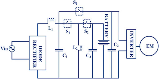
FIGURE 6. Single-stage non-isolated PEV charger.
In the study of Praneeth and Williamson (2019), they proposed non-isolated OBC-operated independent PWM for buck and boost mode to retain good input power quality. A two-mode average current-mode control is designed to operate in a wide output voltage range with high input power quality. The control logic block enables the independent control of PWM for boost and buck switches that consists of a comparator, switch block, and logical gates. The transition of the boost to buck mode and vice versa depends on the demand for output voltage. When low input voltage losses are high and high total harmonic distortion at the input, in this context, charging the battery through not only in the plug-in mode but also through regenerative braking and PV charging which are both conducted in on-board chargers. For regenerative braking to charge the battery in a single-stage unidirectional charger with fewer switches, an effective control technique is given.
Though the single-stage chargers have high input power quality, it contains the low-frequency ripples that worsen the battery performance and decoupling circuits are required to suppress the second harmonic effects. It leads to complex controller design and higher-order systems in controller design. The uncontrolled rectifier causes the accountable conduction loss as challenges of single-stage charger and output power, charging mode, and harmonic distortion which are shown in Table 2. The power ratings of single-stage unidirectional chargers are needed to improve for heavy vehicle charging in either one method that reduces the battery performance.
4.2 Two-stage unidirectional chargers
4.2.1 Power factor converter
The conventional EV charger consists of a diode bridge rectifier and has adverse power quality issues due to nonlinear input (Kushwaha and Singh, 2020). A two-stage AC–DC converter prefers better PQ in an EV charger since it has some limitations that the additional switching circuit and control circuitry (Kushwaha and Singh, 2019). A front stage is a rectifier circuit with a power factor correction (PFC) boost converter to attain a high-power factor and less harmonic distortion (Mc Donald and Lough, 2021). The rectifier level can be a half-bridge, full-bridge, or multilevel diode bridge. A half-bridge rectifier has a low cost since it has a smaller number of diodes/switches. The diode bridge rectifier is more complex and the components are subjected to lower stresses (Musavi et al., 2011a). The multilevel configuration gives a high-power rating to the AC–DC converter.
A bidirectional power flow can be obtained by replacing all the diodes with active switches. The interleaved topology is preferable in power factor converters. The interleaved boost converter is proposed (Hu et al., 2018) with a lower peak current and less ripple at the output voltage. As shown in Figure 7, an interleaved boost converter consists of two boost converters in parallel, operating 180° out of the phase (Lee et al., 2000). The interleaving method reduces the input current ripple and improves the output voltage, and also reduces the size of the EMI filter (Hu et al., 2017). The two-switch buck–boost cascaded PFC converters can give the output voltage less and above the given input voltage (Praneeth et al., 2019) and variable DC-link voltage provides the smooth transition between a buck to boost mode and vice versa Figure 8. This PFC converter with DC–DC converter gives a wide range of output voltage with a good power quality at the input.
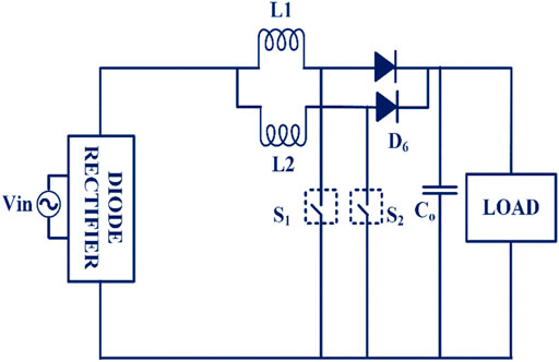
FIGURE 7. Full-bridge rectifier with interleaved PFC boost converter.
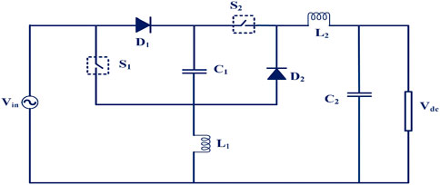
FIGURE 8. Buck–boost PFC converter.
The diode bridge and PFC boost converter are the lossy networks in conventional active front-end topology (AFE) as it uses diode bridge and AFE work in a CCM mode. This topology needs the PLL circuit to synchronize with the grid and control complexity with more devices (Musavi et al., 2011b). Unless a conventional bridge rectifier PFC converter is used, the single bridgeless buck–boost converter in Figure 9 connected with a voltage doubler circuit connects with a DC–DC converter that operates in DCM to attain PFC for wide input voltage variation (Dixit et al., 2020).
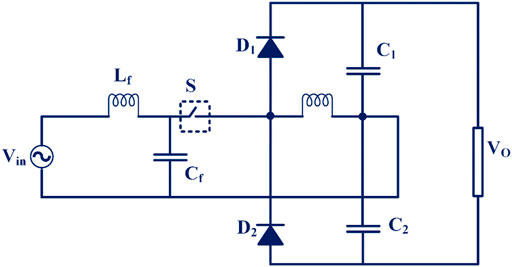
FIGURE 9. Bridgeless PFC converter.
Despite more merits such as lower voltage stress, reduced number of sensors, soft turn-on of switches, and lower control complexity, it needs high-rated switching components. Since the bridgeless totem-pole PFC in Figure 10, output is connected with input by a slow diode and half-line, and no CM interference occurs. It has the capacity of bidirectional conversion and also achieves ZCS throughout a wide range of loads with a low line input (Su and Lu, 2010). In Table.3, the PFC converter operates under the boost mode and suffers from high voltage stress with less efficiency, the interleave converter shares the stress but control complexity is more by adding the more networks.
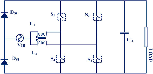
FIGURE 10. Totem-pole PFC.

TABLE 3. PFC converter summary.
4.2.2 DC-link capacitor
The input supply frequency ripple determines the DC-link capacitor size (Singh et al., 2017) that is needed for energy storage when the charger delivers direct power (Xue et al., 2013) and connects between the active front-end devices and DC–DC converter topology (Xue et al., 2015). Since the DC-link capacitor is an electrolytic capacitor and has a short lifespan, it is not preferable for on-board chargers. The DC-link capacitors size has been reduced by sinusoidal charging techniques for the battery so that it does not have a considerable impact on battery life degradation (Prasad et al., 2015). A thin-film capacitor is an alternative to electrolytic capacitors that is too expensive and bulky (Li et al., 2013b). The feed-forward controller and repetitive algorithm, as well as advanced control techniques, can remove distortion in output current such that the size of the DC-link capacitor can be low in size.
4.2.3 DC–DC converter topologies
Currently, high switching frequencies at the 10 kHz DC–DC converter are widely used (Shin and Lee, 2014). Despite many merits of high switching frequency such as less volume, it has many problems such as increasing EMI, switching loss, and less efficiency (Tao et al., 2019). To overcome these problems, soft-switching technologies are preferred which are ZVS, ZCS, and LLC (Chen, 2011; Hariya et al., 2016). The drawback of PSFFB is the loss of ZVS function at light load and the duty cycle problem (Wang et al., 2017).
4.2.3.1 Interleaved topologies
The interleave converter proposed with a synchronous PWM signal causes high inductor current on buck mode and hence conduction loss is more. In the study of Kim and Lee (2017), they proposed the converter Figure 11 which is a single-stage converter that improves system efficiency in the step-down by the asymmetric control algorithm. The asymmetric algorithm controls each switch asymmetrically using a phase-shift control. The inductor is designed based on the algorithm that reduces the size and inductance value and reduces the inductor ripple current. The proposed converter needs two clock counters to generate the PWM signal for buck switches. It made additional circuits to the converter than the conventional synchronous algorithm.
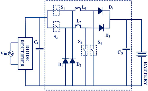
FIGURE 11. Interleaved non-isolated on-board charger.
4.2.3.2 LLC resonant converter topologies
The LLC converter has the feature of soft switching under wide load variation. As a result, the rectifying diode experiences the low-voltage stress and there is no need for snubber circuits. However, it causes low efficiency at light load due to high-switching frequency. The charger has to charge the battery in a wide voltage range, a converter designed to meet high voltage gain. As a result, a large conduction current makes conduction loss. The LLC converter supports a wide output voltage with good efficiency. However, it suffers from the size of the resonant components. Hence two small transformers connected in parallel-series forms with a half-bridge LLC (Lin and Dong, 2011) improve the power density and fail to support high input voltage and high power. In the study of Shen et al. (2018), a full-bridge LLC Figure 12 with two same transformers is series-connected at the primary side to obtain the same primary side current and parallel-connected at the secondary side to get the same secondary voltage so that power is equal between these two transformers. The size of the transformer reduces as well as the cooling of the transformed is improved. But voltage stress on the diode is gradually reduced when the output voltage reaches maximum.
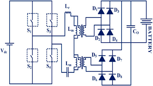
FIGURE 12. Full-bridge LLC resonant converter with dual transformer.
In the study of Ta et al. (2020), the dual LLC converter consists of the wide-bandgap device with two transformers connected in series and it is secondary connected with a voltage doubler rectifier circuit. To improve the light load efficiency when the output voltage is half of the rated input, one phase LLC only turns on while the other is off in a dual-phase structure converter. ZVS switching is realized in all three modes of operation so that the converter weight and size can be reduced. The leakage inductance is not equal in two transformers which causes an imbalance in transformer current during the converter operation and converter topologies, output power is depicted in Table 4 and the LLC converter frequency ranges are depicted in Table 5. The dual transformer improves voltage gain through control complexity but the cost is high.
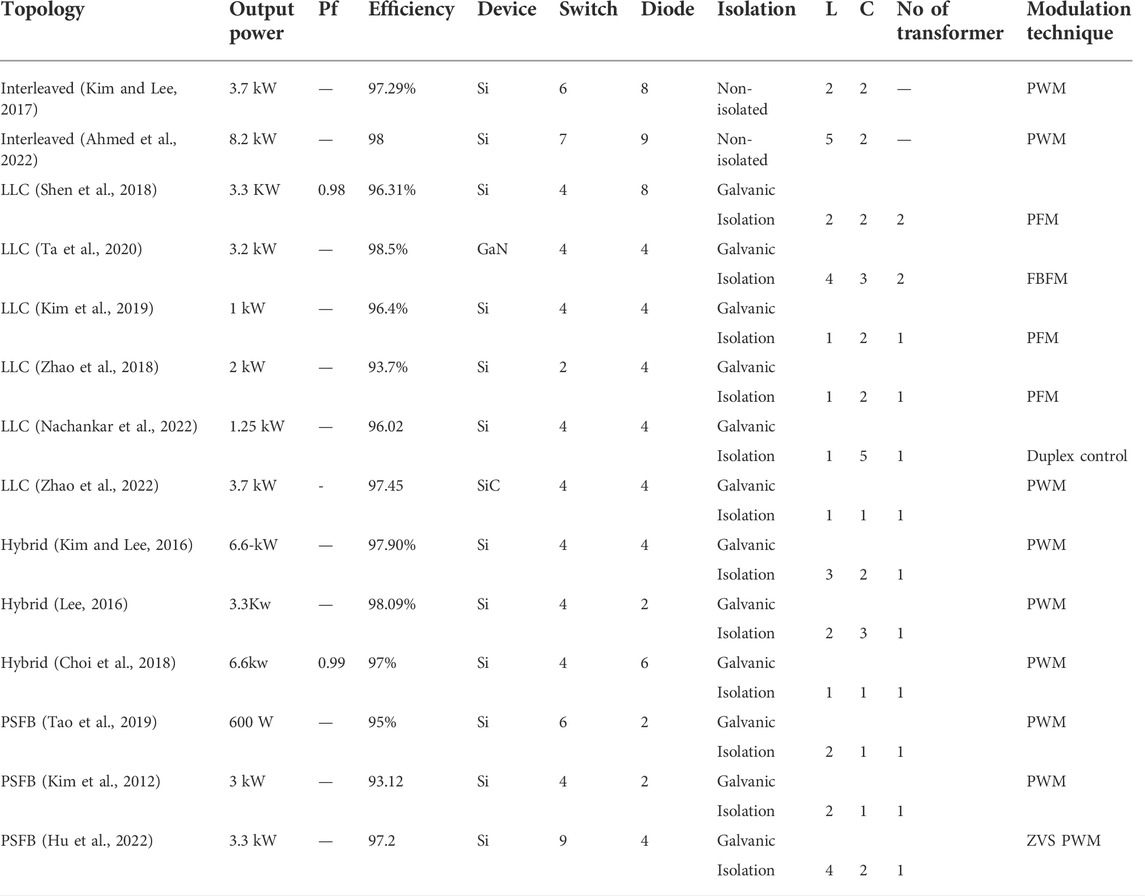
TABLE 4. Two-stage unidirectional converter summary.
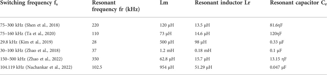
TABLE 5. LLC converter frequency range summary.
4.2.3.3 Hybrid topologies
In the study of Kim and Lee (2016), a full-bridge converter and a resonant converter are coupled with a transformer to form the hybrid converter shown in Figure 13. Among the two-way power flow to the battery, one is from the full-bridge operation; another way is series resonance with the diode when full-bridge power becomes zero. So that it improves the converter gain, and reduces turn-off voltage spikes across the diode due to transformer leakage inductance and junction capacitance that improves the converter efficiency. Since the hybrid converter uses a low rating of rectifier diodes at the full-bridge side with fewer turns of the transformer, the snubber circuit can avoid. On the secondary side of the converter diode, components are high.
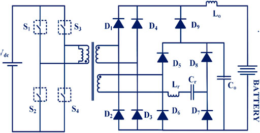
FIGURE 13. Full-bridge series-resonant tank converter.
In the study of Lee (2016), PSFB combined with LLC converter is used for on-board charger reducing the circulating current with the fixed switching frequency. The energy recovery circuit overcomes the ZVS lagging leg problem and reduces the large circulation current by rectifying the diode. The size of the two transformers is less when compared with a single transformer because the utilization of two transformers is high compared with a single transformer with the same power capacity. Using the constant current and voltage algorithm methods, battery is charged and controlled by two PI controllers. In the study of Choi et al. (2018), a hybrid PWM DC/DC converter comprising a full-bridge converter with the resonant converter is proposed. Switching characteristics are similar to the PWM resonant converter. Transformer leakage inductance utilizes a resonant inductor that eliminates voltage spikes produced by the diode junction capacitance. The proposed charger does not need a dissipative snubber circuitry and output filter. The efficiency of the charger is slightly low when it reaches the rated load and the switching frequency is shown in Table 6.

TABLE 6. Hybrid converter frequency range summary.
4.2.3.4 Phase-shift full-bridge topologies
In the study of Tao et al. (2019), the proposed improved ZVS phase-shifted full-bridge DC/DC converter Figure 14 utilizes the clamping diodes in both the primary and secondary sides of the transformer to eliminate the voltage oscillation and improve the soft-switching range. Synchronous rectification in transformer secondary is to improve efficiency. Changing the switching frequency can increase the phase-shift angle under light load and decrease the phase-shift angle under heavy load to reduce circulating energy and keep ZVS on. To minimize the circulating current losses, the duty cycle method, fundamental component approximation, and optimal phase-shift ratio are used. On the other hand, the minimum amount of circulating current is used to achieve ZVS on.
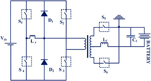
FIGURE 14. Full-bridge ZVS DC/DC converter.
The current doubler circuit is used at the output of the converter that minimizes the current ripple and current ratings (Kim et al., 2012). The current doubler circuit is minimizing the secondary current rating of the transformer, and the effective frequency of the output capacitor is twice the switching frequency. The magnetic loss of the transformer is increasing for a wide range of battery charging. Electrolytic capacitors present in two-stage chargers jeopardize system reliability because of the short life which is used for DC-link. The voltage doubler configuration has been proposed to reduce secondary component voltage stress by up to half of the output voltage. Because this configuration increases the number of transformers, separating the battery stack into two modules is an alternative method.
5 Charging standards and safety standards
United States–based electric vehicle manufacturers are following the Society for Automobile Engineers (SAE) and IEEE standards while the European countries follow the International Electromechanical Commission (IEC). Japan has its EV charging standards named Japan Electric Vehicle Association (JEVS). The electric vehicle standards and safety standards dealing with both AC and DC charging with supporting equipment are depicted in Table 7.

TABLE 7. Standards of electric vehicle charging and safety.
Most EV firms are unwilling to release comprehensive topology details about their bidirectional OBCs due to privacy concerns shown in Table 8 and from the research article, various charger topology performances are shown in Table 9.
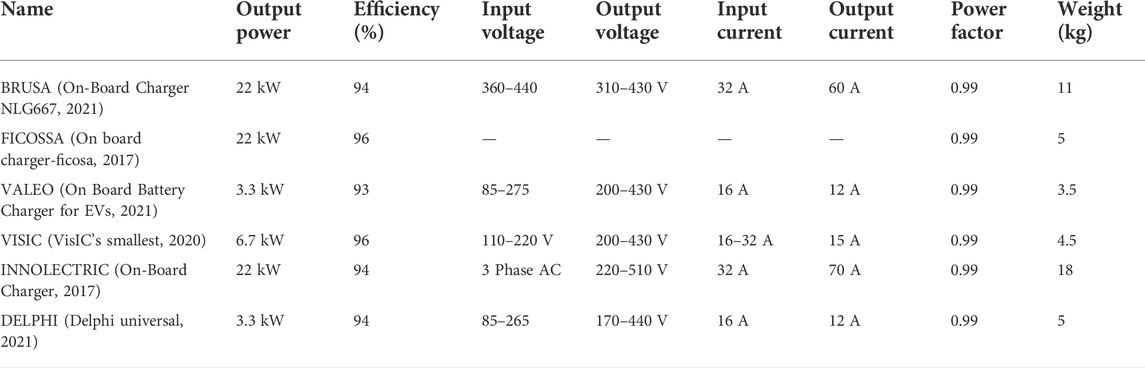
TABLE 8. Commercial on-board charger summary.
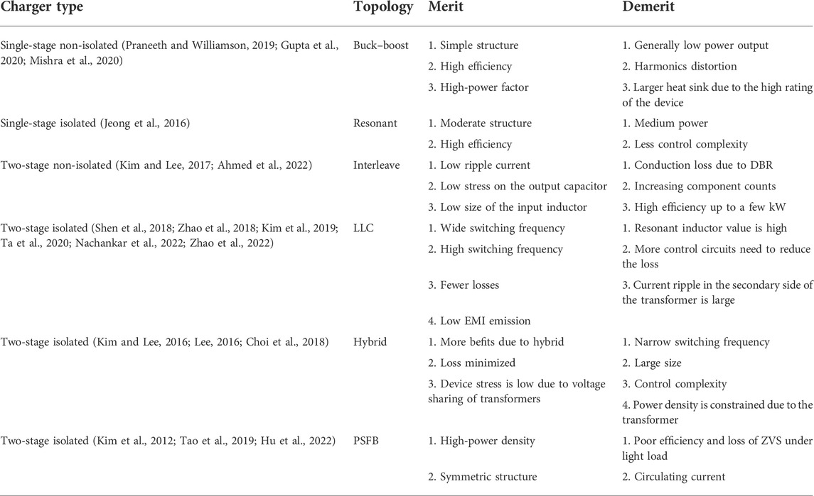
TABLE 9. Unidirectional charger comparison.
In Table 10, benefits of unidirectional chargers include a reduction in total PFC circuit components and reduced cost and enhanced functionality such as adjustable power factor control. To overcome the diode bridge rectifier causing considerable conduction loss, bridgeless PFC is proposed with optimization techniques. As the bidirectional chargers can support a lot of desirable features, they demand additional circuit components, which raises the burden on cost savings and dependability and may marginally degrade the OBC’s power density and weight. No specific hardware is required except the outlet, and it also reduces the battery deformations that are mainly involved in bidirectional charging. To implement the unidirectional charging station, no additional cost is needed, whereas in implementing the bidirectional charging station, additional costs with efficient technological advancement are needed to supply reactive power to the grid for regulations.
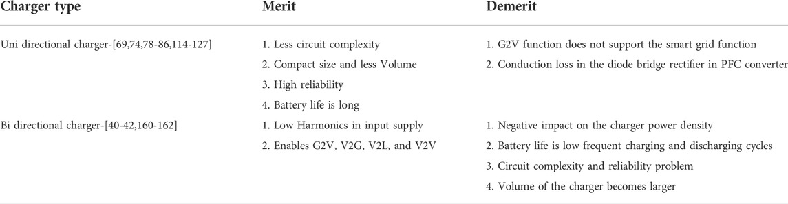
TABLE 10. Unidirectional and bidirectional charger comparison.
6 Charging trends in future and challenges
6.1 Utilization of the motor drive system with the charger
The utilization of the existing inverter and motor winding for charging the battery gives a better solution for the on-board chargers that added weight to the vehicle due to passive devices (Rivera et al., 2015). It enables a higher charging level with a near to unity power factor in both unidirectional and bidirectional chargers (Habib et al., 2015), (Habib and Kamran, 2014). The integrated charger utilizes the winding of an induction motor (IM), permanent magnetic motor (PM), switched reluctance motor (SRM), and multiphase motor (He et al., 2021). The integrated charger needs the mechanical contact switch to access the motor winding on a charging (De Sousa et al., 2010). The main challenge of an integrated charger system is to ensure zero torque output during stationary operation (Subotic et al., 2016).
6.2 Wide-bandgap devices
Wide-bandgap (WBG) devices are used to improve the power density, and efficiency, and lower the size and cost than Silicon-based devices (Su and Tang, 2015). Si carbide has high thermal conductivity, higher junction temperature, and less co-efficient thermal expansion making the SiC devices more reliable over a wide range of temperatures (Hudgins et al., 2003). The SiC MOSFET is promising for EV chargers that require extremely high efficiency and high density (Li, 2018). An E-mode GaN HEMT on-board charger with maximum density is demonstrated (Lu et al., 2015). The development of wide-bandgap (WBG) devices is eliminating the need for a series low voltage MOSFET and parallel fast recovery diode (Liu et al., 2017).
6.3 Inductive charging
Recently, inductive charging is an alternative technology for on-board and off-board charging because it replaces the wired interface between the vehicle and power source (Mude, 2018). The vehicle is charging through the electromagnetic induction principle or it is said to wireless charging method. Inductive charging offers many benefits over conductive charging solutions for electric vehicles such as safety, no manual interaction, and the possibility of dynamic inductive charging (Ahmad et al., 2018; Patil et al., 2018). The increase in charging points leads to reduction in the size of the battery pack. This reduces the cost and weight of the vehicle. In conductive charging, cable insulation damage and worn conductor problem caused by contact friction in harsh environments such as underground and underwater are not in inductive charging that improves the safety and reliability (Kan et al., 2018). According to research studies optimizing the shape, arrangement, and number of turns in transmission and receiving coils can improve efficiency (Imura et al., 2009; Lee and Lorenz, 2011).
6.4 Vehicle-to-grid
To maintain the power system stability and reliability, vehicle-to-grid technology assists that battery power to the grid on demand (Hoang et al., 2017; Uddin et al., 2018). Vehicle-to-grid (V2G) technology significantly reduces the investment of money to install a new power generation infrastructure (Tan et al., 2016b). EVs also can function as an energy resource through vehicle-to-grid (V2G) operation by sending electricity back to the grid, thereby preventing or postponing load shedding (Daim et al., 2016). The subsection of V2G is like vehicle-to-home (V2H) and vehicle-to-building (V2B), both of which draw power directly from the EV rather than through the power grid. EV is plugged into the power grid system under idle conditions and the batteries are served as the distributed storage system when there is unpredictability of renewable source energy in power gird (Goel et al., 2021). The distributed energy resource (DER) is on a larger scale and with greater significance (Buja et al., 2017). This market is just emerging, however, taking into account the number of electric vehicles and the energy stored in their batteries will have a significant impact on system services in the power grid.
6.5 Renewable energy–based charging
The research has been carried out to integrate solar energy, electric vehicle, and grid with multifunctional operation on demand of power (Chandra Mouli et al., 2019). Solar PV panels are connected with the motor winding through the neutral point to charge the battery while the vehicle is under idle and driving conditions that are kept on the roof of the vehicle (Yu et al., 2022). The solar PV-mounted electric vehicle charging ensures driving range improvement as well as cost reduction on plug-in charging (Shrivastava et al., 2019). In the study of Divyapriya et al. (2021), they proposed the collective of unused battery power in street is connected to the grid to charge the electric vehicle depicted in Figure 15. By design, the recursive filter with the perturbing and observer algorithm-based solar PV with grid eliminates the fundamental frequency in the grid as well as the fast response for sudden changes in load current (Chauhan and Singh, 2019).
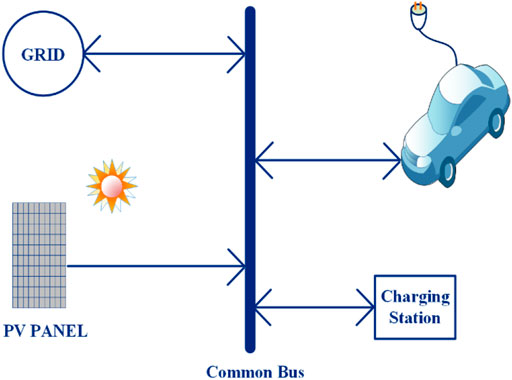
FIGURE 15. Renewable energy with grid EV charging.
Various issues in integrating renewable energy systems with smart grids and control strategies have been discussed (Thirunavukkarasu and Sawle, 2021b). To reduce the reliance on fossil fuels, the authors designed a hybrid renewable-based energy system to satisfy the energy requirements of remote area households (Thirunavukkarasu and Sawle, 2020). The potential of available renewable energy resources for various locations in India has been investigated and a stand-alone renewable energy system has been developed to electrify remote areas (Thirunavukkarasu and Sawle, 2021a). Several optimization techniques have been discussed to optimize the system components, and by using the HOMER optimization technique, the optimal sizing of the components of a hybrid renewable energy system has been extracted (Sawle and Thirunavukkarasu, 2021). Due to the limited issues of conventional fuel, the development of renewable energy-based electricity generation and hydrogen fuel to drive vehicles has attracted a great deal of attention. The authors focused on investigating the requirements of solar, wind, battery, and converter requirements to meet three different loads, such as electric, thermal, and hydrogen (Thirunavukkarasu and Sawle, 2022).
6.6 Challenges
Furthermore, the development of bidirectional OBC presents infrastructure issues in the related business. First and foremost, the bidirectional power flow must be compatible with modern smart grid functions. The converter efficiency and power density have relied on component count as well as saturation of the transformer inductance to limit the efficiency. A two-stage charger control design is fairly complicated because it necessitates two separate controllers for both converters. As the power density and efficiency of the charger depends on the size and reduction of the passive components such as transformer, capacitor, and inductor; effective optimal design and optimal circuit topology are needed (Merlin Mary and Sathyan, 2021). It is achieved by reducing device current stress and ripples allowing for the use of smaller devices, resulting in a smaller charger with a lower cost. It is necessary to forecast the availability of electric vehicles at a given time, as well as their energy requirements, strategies to improve voltage regulations, and the grid voltage profile. Due to the depletion of fossil fuels, it is necessary to integrate renewable energy sources and utilize their energy to charge electric vehicles. Finally, optimizations of various parameters of converter components are required to minimize in terms of sizing and cost requirements.
7 Conclusion
This review article provides an overview of the different types of on-board chargers in electric vehicles and their different levels of charging standards are discussed. Details of various charging methods and on-board charger topologies of single-stage, two-stage chargers of isolated and non-isolated topologies are studied. The single-stage charger reduces the volume of the charger and can support the higher rating, and research studies are in progress since the DC-link capacitor is not present. The usage of wide-bandgap devices in an on-board charger has a good impact on its size, weight, and volume and also improves the energy level that reduces the charging time. The off-board charger has the key benefit of quick charging of the battery but it needs good infrastructure. In inductive charging, the system reduces the battery size and improves the efficiency of the vehicle. V2G and solar PV–enabled charging technology can be considered as the possible distributed energy source that can support the power system in the future storage requirements and costs. On-board chargers should be compatible with both single and three-phase voltage supplies. To accomplish good efficiency, advanced modulation techniques with machine learning are needed for the soft-switching of semiconductors.
Author contributions
SV: conceptualization, investigation, and writing–original draft. NS: validation and supervision.
Conflict of interest
The authors declare that they have no known competing financial interests or personal relationships that could have appeared to influence the work reported in this study.
Publisher’s note
All claims expressed in this article are solely those of the authors and do not necessarily represent those of their affiliated organizations, or those of the publisher, the editors, and the reviewers. Any product that may be evaluated in this article, or claim that may be made by its manufacturer, is not guaranteed or endorsed by the publisher.
References
Abusara, M. A., and Sharkh, S. M. (2013). Design and control of a grid-connected interleaved inverter. IEEE Trans. Power Electron. 28 (2), 748–764. doi:10.1109/tpel.2012.2201505
Ahmad, A., Alam, M. S., and Chabaan, R. (2018). A comprehensive review of wireless charging technologies for electric vehicles. IEEE Trans. Transp. Electrific. 4 (1), 38–63. doi:10.1109/tte.2017.2771619
Ahmed, N. A., Alajmi, B. N., Abdelsalam, I., and Marei, M. I. (2022). Soft switching multiphase interleaved boost converter with high voltage gain for EV applications. IEEE Access 10, 27698–27716. doi:10.1109/access.2022.3157050
Ahourai, F., Huang, I., and Faruque, M. A. A. (2013). Modeling and simulation of the EV charging in a residential distribution power grid. [Internet]. arXiv [cs.SY]. Available at: http://arxiv.org/abs/1311.6005.
Basso, T., Chakraborty, S., Hoke, A., and Coddington, M. (2015). “IEEE 1547 Standards advancing grid modernization,” in : 2015 IEEE 42nd photovoltaic specialist conference (PVSC) (IEEE).
Berjoza, D., and Jurgena, I. (2015). Analysis of distribution of electric vehicle charging stations in the Baltic. Eng. Rural. Dev. 14, 258–264.
Blau, P. J. (1998). “Four great challenges confronting our understanding and modelling of sliding friction**Research sponsored by the U. S. Department of Energy,” in Assistant secretary for energy efficiency and renewable energy, office of transportation technologies, as part of the heavy vehicle propulsion system materials program, under contract DE-AC05-960r22464 with lockheed martin energy research corporation (Elsevier).
Bojrup, M., Karlsson, P., Alakula, M., and Simonsson, B. (2002). “A dual-purpose battery charger for electric vehicles,” in PESC 98 record 29th annual IEEE power electronics specialists conference (cat No98CH36196) (IEEE).
Buja, G., Bertoluzzo, M., and Fontana, C. (2017). Reactive power compensation capabilities of V2G-enabled electric vehicles. IEEE Trans. Power Electron. 32 (12), 9447–9459. doi:10.1109/tpel.2017.2658686
Celli, G., Soma, G. G., Pilo, F., Lacu, F., Mocci, S., and Natale, N. (2014). “Aggregated electric vehicles load profiles with fast charging stations,” in 2014 Power Systems Computation Conference (IEEE).
Chae, H-J., Moon, H-T., and Lee, J-Y. (2010). On-board battery charger for PHEV without high-voltage electrolytic capacitor. Electron. Lett. 46 (25), 1691. doi:10.1049/el.2010.2710
Chandra Mouli, G. R., Schijffelen, J., van den Heuvel, M., Kardolus, M., and Bauer, P. (2019). A 10 kW solar-powered bidirectional EV charger compatible with chademo and COMBO. IEEE Trans. Power Electron. 34 (2), 1082–1098. doi:10.1109/tpel.2018.2829211
Channegowda, J., Pathipati, V. K., and Williamson, S. S. (2015). “Comprehensive review and comparison of DC fast charging converter topologies: Improving electric vehicle plug-to-wheels efficiency,” in 2015 IEEE 24th international symposium on industrial electronics (ISIE) (IEEE).
Chauhan, S., and Singh, B. (2019). Grid-interfaced solar PV powered electric vehicle battery system with novel adaptive digital control algorithm. IET Power Electron. 12 (13), 3470–3478. doi:10.1049/iet-pel.2019.0025
Chaurasiya, S., and Singh, B. (2019). “A G2V/V2G off-board fast charger for charging of lithium-ion based electric vehicles,” in 2019 IEEE International Conference on Environment and Electrical Engineering and 2019 IEEE Industrial and Commercial Power Systems Europe (EEEIC/I&CPS Europe) (IEEE).
Chen, K-K. (2011). A novel application of zero-current-switching quasi resonant buck converter for battery chargers. Math. Probl. Eng. 2011, 1–16. doi:10.1155/2011/481208
Chen, L., Wu, M., and Xu, X. (2012). “The development and applications of charging/battery swap technologies for EVS,” in 2012 China International Conference on Electricity Distribution (IEEE).
Cheng, L., Chang, Y., Wu, Q., Lin, W., and Singh, C. (2014). Evaluating charging service reliability for plug-in EVs from the distribution network aspect. IEEE Trans. Sustain. Energy 5 (4), 1287–1296. doi:10.1109/tste.2014.2348575
Choi, J-Y., Choi, S-W., and Lee, J-Y. (2018). Hybrid PWM DC/DC converter for EV on-board charger with single transformer. EPE J. 28 (2), 63–74. doi:10.1080/09398368.2018.1425525
Choi, W-Y., Yang, M-K., and Cho, H-S. (2014). High-frequency-link soft-switching PWM DC–DC converter for EV on-board battery chargers. IEEE Trans. Power Electron. 29 (8), 4136–4145. doi:10.1109/tpel.2013.2288364
Dai, J., and Ludois, D. C. (2015). A survey of wireless power transfer and a critical comparison of inductive and capacitive coupling for small gap applications. IEEE Trans. Power Electron. 30 (11), 6017–6029. doi:10.1109/tpel.2015.2415253
Daim, T. U., Wang, X., Cowan, K., and Shott, T. (2016). Technology roadmap for smart electric vehicle-to-grid (V2G) of residential chargers. J. Innov. Entrep. 5 (1), 15. doi:10.1186/s13731-016-0043-y
Das, H. S., Rahman, M. M., Li, S., and Tan, C. W. (2020). Electric vehicles standards, charging infrastructure, and impact on grid integration: A technological review. Renew. Sustain. Energy Rev. 120 (109618), 109618. doi:10.1016/j.rser.2019.109618
De Sousa, L., Silvestre, B., and Bouchez, B. (2010). “A combined multiphase electric drive and fast battery charger for Electric Vehicles,” in 2010 IEEE Vehicle Power and Propulsion Conference (IEEE).
Dell, R. M., Moseley, P. T., and David, A. J. R. (2014). Towards sustainable road transport. Academic Press.
Delphi universal (2021). Delphi universal on-board Battery Charger - delphi power train - PDF catalogs [Internet]. Directindustry.com. [cited 2021 Aug 12]. Available at: https://pdf.directindustry.com/pdf/delphi-power-train/delphi-universal-on-board-battery-charger/54988-325673.html.
Diaz, M. N. (2021). Electric vehicles: A primer on technology and selected policy issues [internet]. Everycrsreport.com. [cited 2021 Aug 11]. Available at: https://www.everycrsreport.com/files/20200214_R46231_7ad363d95b696b0da7c61a7e6ecb5f6e3495b16b.pdf.
Divyapriya, S., Amudha, A., and Vijayakumar, R. (2021). Design of solar smart street light powered plug-in electric vehicle charging station by using internet of things. J. Inst. Eng. India. Ser. B 102 (3), 477–486. doi:10.1007/s40031-021-00548-y
Dixit, A., Pande, K., Gangavarapu, S., and Rathore, A. K. (2020). DCM-based bridgeless PFC converter for EV charging application. IEEE J. Emerg. Sel. Top. Ind. Electron. 1 (1), 57–66. doi:10.1109/jestie.2020.2999595
Dusmez, S., and Khaligh, A. (2013). A compact and integrated multifunctional power electronic interface for plug-in electric vehicles. IEEE Trans. Power Electron. 28 (12), 5690–5701. doi:10.1109/tpel.2012.2233763
Dutta, S., Gangavarapu, S., Rathore, A. K., Singh, R. K., Mishra, S. K., and Khadkikar, V. (2022). Novel single-phase cuk-derived bridgeless PFC converter for on-board EV charger with reduced number of components. IEEE Trans. Ind. Appl. 58 (3), 3999–4010. doi:10.1109/tia.2022.3148969
Egan, M. G., O’Sullivan, D. L., Hayes, J. G., Willers, M. J., and Henze, C. P. (2007). Power-factor-corrected single-stage inductive charger for electric vehicle batteries. IEEE Trans. Ind. Electron. 54 (2), 1217–1226. doi:10.1109/tie.2007.892996
Falvo, M. C., Sbordone, D., Bayram, I. S., and Devetsikiotis, M. (2014). “EV charging stations and modes: International standards,” in 2014 international symposium on power electronics, electrical drives, automation and motion (IEEE).
Feng, H., Tavakoli, R., Onar, O. C., and Pantic, Z. (2020). Advances in high-power wireless charging systems: Overview and design considerations. IEEE Trans. Transp. Electrific. 6 (3), 886–919. doi:10.1109/tte.2020.3012543
Gautam, D. S., Musavi, F., Edington, M., Eberle, W., and Dunford, W. G. (2012). An automotive onboard 3. 3-kW battery charger for PHEV application. IEEE Trans. Veh. Technol. 61 (8), 3466–3474. doi:10.1109/tvt.2012.2210259
Ghorbal, M. J-B., Ghzaiel, W., Slama-Belkhodja, I., and Guerrero, J. M. (2012). “Online detection and estimation of grid impedance variation for Distributed Power Generation,” in 2012 16th IEEE Mediterranean Electrotechnical Conference (IEEE).
Goel, S., Sharma, R., and Rathore, A. K. (2021). A review on barrier and challenges of electric vehicle in India and vehicle to grid optimisation. Transp. Eng. 4 (100057), 100057. doi:10.1016/j.treng.2021.100057
Grenier, M., Thiringer, T., and Aghdam, M. G. H. (2010). “Design of on-board charger for plug-in hybrid electric vehicle,” in 5th IET International Conference on Power Electronics, Machines and Drives (PEMD 2010), Brighton, UK Conference (Institution of Engineering and Technology). doi:10.1049/cp.2010.0101
Grunditz, E. A., and Thiringer, T. (2016). Performance analysis of current BEVs based on a comprehensive review of specifications. IEEE Trans. Transp. Electrific. 2 (3), 270–289. doi:10.1109/tte.2016.2571783
Gupta, J., Kushwaha, R., and Singh, B. (2021). Improved power quality transformer less single-stage bridgeless converter-based charger for light electric vehicles. IEEE Trans. Power Electron. 36 (7), 7716–7724. doi:10.1109/tpel.2020.3048790
Gupta, J., Maurya, R., and Arya, S. R. (2020). On‐board electric vehicle battery charger with improved power quality and reduced switching stress. IET power electron. 13 (13), 2885–2894. doi:10.1049/iet-pel.2019.0962
Guru Kumar, G., Sundaramoorthy, K., Athikkal, S., and Karthikeyan, V. (2019). Dual input superboost DC–DC converter for solar powered electric vehicle. IET Power Electron. 12 (9), 2276–2284. doi:10.1049/iet-pel.2018.5255
Habib, S., and Kamran, M. (2014). “A novel vehicle-to-grid technology with constraint analysis-a review,” in 2014 international conference on emerging technologies (ICET) (IEEE).
Habib, S., Kamran, M., and Rashid, U. (2015). Impact analysis of vehicle-to-grid technology and charging strategies of electric vehicles on distribution networks – a review. J. Power Sources 277, 205–214. doi:10.1016/j.jpowsour.2014.12.020
Habib, S., Khan, M. M., Abbas, F., Sang, L., Shahid, M. U., and Tang, H. (2018). A comprehensive study of implemented international standards, technical challenges, impacts and prospects for electric vehicles. IEEE Access 6, 13866–13890. doi:10.1109/access.2018.2812303
Haghbin, S., Lundmark, S., Alakula, M., and Carlson, O. (2011). An isolated high-power integrated charger in electrified-vehicle applications. IEEE Trans. Veh. Technol. 60 (9), 4115–4126. doi:10.1109/tvt.2011.2162258
Hariya, A., Matsuura, K., Yanagi, H., Tomioka, S., Ishizuka, Y., and Ninomiya, T. (2016). Considerations of physical design and implementation for 5 MHz-100 W LLC resonant DC-DC converters. Act Passiv Electron Compon 2016, 11. doi:10.1155/2016/4027406
Hasan, N., Cocar, I., Amely, T., Wang, H., Zane, R., Pantic, Z., et al. (2015). “A practical implementation of wireless power transfer systems for socially interactive robots,” in 2015 IEEE energy conversion congress and exposition (ECCE) (IEEE).
He, S., Xu, Z., Chen, M., Yang, H., and Li, W. (2021). General derivation law with torque-free achieving of integral on-board charger on compact powertrains. IEEE Trans. Ind. Electron. 68 (2), 1791–1802. doi:10.1109/tie.2020.3005063
Hoang, D. T., Wang, P., Niyato, D., and Hossain, E. (2017). Charging and discharging of plug-in electric vehicles (PEVs) in vehicle-to-grid (V2G) systems: A cyber insurance-based model. IEEE Access 5, 732–754. doi:10.1109/access.2017.2649042
Hu, C., Wang, R., Shi, Y., Jia, X., and Xu, D. (2022). A fixed frequency zero-voltage-switching on-board EV charger. IEEE Open J. Power Electron. 3, 75–83. doi:10.1109/ojpel.2021.3133618
Hu, J., Xiao, W., Zhang, B., Qiu, D., and Ho, C. N. M. (2018). “A single-phase hybrid interleaved parallel boost PFC converter,” in 2018 IEEE energy conversion congress and exposition (ECCE) (IEEE).
Hu, X., Meng, Z., Yongchao, L., Li, L., and Wu, G. (2017). A ripple-free input current interleaved converter with dual coupled inductors for high step-up applications. J. Power Electron. 17 (3), 590–600. doi:10.6113/JPE.2017.17.3.590
Hudgins, J. L., Simin, G. S., Santi, E., and Khan, M. A. (2003). An assessment of wide bandgap semiconductors for power devices. IEEE Trans. Power Electron. 18 (3), 907–914. doi:10.1109/tpel.2003.810840
IEC 61000-3-2:2018+AMD1:2020 (2020). CSV. [Internet]. Iec.ch. [cited 2021 Aug 11]. Available at: https://webstore.iec.ch/publication/67329.
IEC 61851-23:2014 (2014). Iec.ch. [Internet]. Iec.ch. [cited 2021 Aug 11]. Available at: https://webstore.iec.ch/publication/6032.
Imura, T., Okabe, H., Uchida, T., and Hori, Y. (2009). “Study on open and short end helical antennas with capacitor in series of wireless power transfer using magnetic resonant couplings,” in 2009 35th annual conference of IEEE industrial electronics (IEEE).
IEA (2019). Global EV Outlook 2019: Scaling-up the transition to electric mobility. Paris: OECD Publishing. doi:10.1787/35fb60bd-en
Itoh, K., Ishigaki, M., Kikuchi, N., Harada, T., and Sugiyama, T. (2020). “A single-stage rectifier with interleaved totem-pole PFC and dual active bridge (DAB) converter for PHEV/BEV on-board charger,” in 2020 IEEE applied power electronics conference and exposition (APEC).
Jain, S., and Kumar, L. (2018). “Fundamentals of power electronics controlled electric propulsion,” in Power electronics handbook (Elsevier), 1023–1065.
Jeong, S-G., Cha, W-J., Lee, S-H., Kwon, J-M., and Kwon, B-H. (2016). Electrolytic capacitor-less single-power-conversion on-board charger with high efficiency. IEEE Trans. Ind. Electron. 63 (12), 7488–7497. doi:10.1109/tie.2016.2590998
Kamalapathi, K., Srinivasa Rao Nayak, P., and Tyagi, V. K. (2021). Design and implementation of dual‐source ( WPT + PV ) charger for EV battery charging. Int. Trans. Electr. Energ. Syst. 31 (11). doi:10.1002/2050-7038.13084
Kan, T., Zhang, Y., Yan, Z., Mercier, P. P., and Mi, C. C. (2018). A rotation-resilient wireless charging system for lightweight autonomous underwater vehicles. IEEE Trans. Veh. Technol. 67 (8), 6935–6942. doi:10.1109/tvt.2018.2836988
Khaligh, A., and Dusmez, S. (2012). Comprehensive topological analysis of conductive and inductive charging solutions for plug-in electric vehicles. IEEE Trans. Veh. Technol. 61 (8), 3475–3489. doi:10.1109/tvt.2012.2213104
Khaligh, A., and Li, Z. (2010). Battery, ultracapacitor, fuel cell, and hybrid energy storage systems for electric, hybrid electric, fuel cell, and plug-in hybrid electric vehicles: State of the art. IEEE Trans. Veh. Technol. 59 (6), 2806–2814. doi:10.1109/tvt.2010.2047877
Kim, B., Kim, M., and Choi, S. (2016). “Single-stage electrolytic capacitor-less AC-DC converter with high frequency isolation for EV charger,” in 2016 IEEE 8th International Power Electronics and Motion Control Conference (IPEMC-ECCE Asia) (IEEE).
Kim, D-H., Kim, M-S., Hussain Nengroo, S., Kim, C-H., and Kim, H-J. (2019). LLC resonant converter for LEV (Light Electric Vehicle) fast chargers. Electronics 8 (3), 362. doi:10.3390/electronics8030362
Kim, D-H., and Lee, B-K. (2017). Asymmetric control algorithm for increasing efficiency of non-isolated on-board battery chargers with a single controller. IEEE Trans. Veh. Technol. 66 (8), 6693–6706. doi:10.1109/tvt.2017.2655118
Kim, S., and Kang, F-S. (2014). Educating medical students in a more optimized way. Korean J. Med. Educ. 1–1, 1–2. doi:10.3946/kjme.2014.26.1.1
Kim, T-H., Lee, S-J., and Choi, W-J. (2012). Design and control of the phase shift full bridge converter for the on-board battery charger of electric forklifts. J. Power Electron. 12 (1), 113–119. doi:10.6113/jpe.2012.12.1.113
Kim, Y-J., and Lee, J-Y. (2016). Full-bridge+SRT hybrid DC/DC converter for a 6.6-kW EV on-board charger. IEEE Trans. Veh. Technol. 65 (6), 4419–4428. doi:10.1109/tvt.2016.2535237
Kumaravel, S., Achathuparambil Narayanankutty, R., Rao, V. S., and Sankar, A. (2019). Dual input–dual output DC–DC converter for solar PV/battery/ultra-capacitor powered electric vehicle application. IET Power Electron. 12 (13), 3351–3358. doi:10.1049/iet-pel.2019.0123
Kushwaha, R., and Singh, B. (2020). Design and development of modified BL Luo converter for PQ improvement in EV charger. IEEE Trans. Ind. Appl., 1. doi:10.1109/tia.2020.2988197
Kushwaha, R., and Singh, B. (2019). UPF‐isolated zeta converter‐based battery charger for electric vehicle. IET Electr. Syst. Transp. 9 (3), 103–112. doi:10.1049/iet-est.2018.5010
Kushwaha, R., and Singh, B. (2022). A bridgeless isolated half-bridge converter based EV charger with power factor preregulation. IEEE Trans. Ind. Appl. 58 (3), 3967–3976. doi:10.1109/tia.2022.3161610
Lee, I-O. (2016). Hybrid PWM-resonant converter for electric vehicle on-board battery chargers. IEEE Trans. Power Electron. 31 (5), 3639–3649. doi:10.1109/tpel.2015.2456635
Lee, J-H., Moon, J-S., Lee, Y-S., Kim, Y-R., and Won, C-Y. (2011). “Fast charging technique for EV battery charger using three-phase AC-DC boost converter,” in IECON 2011 - 37th Annual Conference of the IEEE Industrial Electronics Society (IEEE).
Lee, J. Y., and Chae, H. J. (2014). 6. 6-kW onboard charger design using DCM PFC converter with harmonic modulation technique and two-stage DC/DC converter. IEEE Trans. Ind. Electron. 61 (3), 1243–1252. doi:10.1109/tie.2013.2262749
Lee, P-W., Lee, Y-S., Cheng, D. K. W., and Liu, X-C. (2000). Steady-state analysis of an interleaved boost converter with coupled inductors. IEEE Trans. Ind. Electron. 47 (4), 787–795. doi:10.1109/41.857959
Lee, S-H., and Lorenz, R. D. (2011). Development and validation of model for 95%-efficiency 220-W wireless power transfer over a 30-cm air gap. IEEE Trans. Ind. Appl. 47 (6), 2495–2504. doi:10.1109/tia.2011.2168555
Lee, W-S., Kim, J-H., Lee, J-Y., and Lee, I-O. (2019). Design of an isolated DC/DC topology with high efficiency of over 97% for EV fast chargers. IEEE Trans. Veh. Technol. 68 (12), 11725–11737. doi:10.1109/tvt.2019.2949080
Li, C., Herrera, L., Jia, J., Fu, L., Isurin, A., Cook, A., et al. (2014). Design and implementation of a bidirectional isolated Ćuk converter for low-voltage and high-current automotive DC source applications. IEEE Trans. Veh. Technol. 63 (6), 2567–2577. doi:10.1109/tvt.2013.2294599
Li, H., Zhang, K., Zhao, H., Fan, S., and Xiong, J. (2013). Active power decoupling for high-power single-phase PWM rectifiers. IEEE Trans. Power Electron. 28 (3), 1308–1319. doi:10.1109/tpel.2012.2208764
Li, S., Deng, J., and Mi, C. C. (2013). Single-stage resonant battery charger with inherent power factor correction for electric vehicles. IEEE Trans. Veh. Technol. 62 (9), 4336–4344. doi:10.1109/tvt.2013.2265704
Lin, B-R., and Dong, J-Y. (2011). ZVS resonant converter with parallel–series transformer connection. IEEE Trans. Ind. Electron. 58 (7), 2972–2979. doi:10.1109/tie.2010.2077612
Liu, Z., Li, B., Lee, F. C., and Li, Q. (2017). High-efficiency high-density critical mode rectifier/inverter for WBG-device-based on-board charger. IEEE Trans. Ind. Electron. 64 (11), 9114–9123. doi:10.1109/tie.2017.2716873
Lu, D. D-C., Iu, H. H-C., and Pjevalica, V. (2008). A single-stage AC/DC converter with high power factor, regulated bus voltage, and output voltage. IEEE Trans. Power Electron. 23 (1), 218–228. doi:10.1109/tpel.2007.911787
Lu, J., Tian, Q., Bai, K., Brown, A., and McAmmond, M. (2015). “An indirect matrix converter based 97%-efficiency on-board level 2 battery charger using E-mode GaN HEMTs,” in 2015 IEEE 3rd workshop on wide bandgap power devices and applications (WiPDA) (IEEE).
Masoum, A. S., Deilami, S., Moses, P. S., and Abu-Siada, A. (2010). “Impacts of battery charging rates of Plug-in Electric Vehicle on smart grid distribution systems,” in 2010 IEEE PES Innovative Smart Grid Technologies Conference Europe (ISGT Europe) (IEEE).
Mayordomo, I., Drager, T., Spies, P., Bernhard, J., and Pflaum, A. (2013). An overview of technical challenges and advances of inductive wireless power transmission. Proc. IEEE 101 (6), 1302–1311. doi:10.1109/jproc.2013.2243691
Mc Donald, B., and Lough, B. (2021). Power factor correction (PFC) circuit basics [internet]. Training.ti.com. [cited 2021 Aug 12]. Available at: https://training.ti.com/sites/default/files/docs/power_factor_correction_circuit_basics_-_paper.pdf.
Merlin Mary, N. J., and Sathyan, S. (2022). Design and controller implementation of 3.3 kW bridgeless boost-fed three-level resonant converter for EV battery charging. Electr. Eng. 104, 1935–1949. doi:10.1007/s00202-021-01416-0
Miller, J. M., Onar, O. C., and Chinthavali, M. (2015). Primary-side power flow control of wireless power transfer for electric vehicle charging. IEEE J. Emerg. Sel. Top. Power Electron. 3 (1), 147–162. doi:10.1109/jestpe.2014.2382569
Mishra, A. K., Singh, A. K., and Kim, T. (2020). Reduced component, buck–boost converter for plug‐in electric vehicles with a current sensing‐based efficient NLCC technique. IET power electron. 13 (16), 3753–3763. doi:10.1049/iet-pel.2020.0003
Mude, K. N. (2018). Battery charging method for electric vehicles: From wired to on-road wireless charging. Chin. J. Electr. Eng. 4 (4), 1–15. doi:10.23919/cjee.2018.8606784
Musavi, F., Eberle, W., and Dunford, W. G. (2011). A high-performance single-phase bridgeless interleaved PFC converter for plug-in hybrid electric vehicle battery chargers. IEEE Trans. Ind. Appl. 47 (4), 1833–1843. doi:10.1109/tia.2011.2156753
Musavi, F., Edington, M., Eberle, W., and Dunford, W. G. (2011). Energy efficiency in plug-in hybrid electric vehicle chargers: Evaluation and comparison of front-end AC-DC topologies.
Nachankar, P. P., Suryawanshi, H. M., Chaturvedi, P., Atkar, D., Narayana, C. L., and Govind, D. (2022). Design of electric vehicle battery charger with reduced switching frequency variation. IEEE Trans. Ind. Appl., 1–13. doi:10.1109/tia.2022.3195187
Nachinarkiniyan, S., and Subramanian, K. (2020). Off-board electric vehicle battery charger using PV array. IET Electr. Syst. Transp. 10, 291–300. doi:10.1049/iet-est.2019.0035
On Board Battery Charger for EVs (2021). Valeo. (3.3kW 180-430Vdc) - [Internet]. Evolveelectrics.com. [cited 2021 Aug 12]. Available at: https://evolveelectrics.com/products/valeo-siemens-3-3kw-200-430vdc-charger.
On board charger-ficosa (2017). Ficosa.com. [Internet]. [cited 2021 Aug 12]. Available at: https://www.ficosa.com/products/emobility/on-board-charger/.
On-Board Charger (2017). Innolectric.ag. [Internet][cited 2021 Aug 12]. Available at: https://innolectric.ag/on-board-charger-2-2/?lang=en.
On-Board Charger NLG667 (2021). Brusa.biz. [cited 2021 Aug 12]. Available at: https://www.brusa.biz/portfolio/nlg667/.
Padmagirisan, P., and Sankaranarayanan, V. (2019). Powertrain control of a solar photovoltaic-battery powered hybrid electric vehicle. Front. Energy 13, 296–306. doi:10.1007/s11708-018-0605-8
Pan, L., and Zhang, C. (2015). A high power density integrated charger for electric vehicles with active ripple compensation. Math. Probl. Eng. 2015, 1–18. doi:10.1155/2015/918296
Patil, D., and Agarwal, V. (2016). Compact onboard single-phase EV battery charger with novel low-frequency ripple compensator and optimum filter design. IEEE Trans. Veh. Technol. 65 (4), 1948–1956. doi:10.1109/tvt.2015.2424927
Patil, D., McDonough, M. K., Miller, J. M., Fahimi, B., and Balsara, P. T. (2018). Wireless power transfer for vehicular applications: Overview and challenges. IEEE Trans. Transp. Electrific. 4 (1), 3–37. doi:10.1109/tte.2017.2780627
Patil, D., Sinha, M., and Agarwal, V. (2012). “A cuk converter based bridgeless topology for high power factor fast battery charger for Electric Vechicle application,” in 2012 IEEE Transportation Electrification Conference and Expo (ITEC) (IEEE).
Praneeth, A. V. J. S., Vincent, D., and Williamson, S. S. (2019). “A universal on-board battery charger with wide output voltage range for electric transportation,” in 2019 IEEE energy conversion congress and exposition (ECCE) (IEEE).
Praneeth, A. V. J. S., and Williamson, S. S. (2019). Modeling, design, analysis, and control of a non-isolated universal on-board battery charger for electric transportation. IEEE Trans. Transp. Electrific. 5 (4), 912–924. doi:10.1109/tte.2019.2919197
Praneeth, A. V. J. S., and Williamson, S. S. (2022). A zero-voltage, zero-current transition boost cascaded-by-buck PFC converter for universal E-transportation charging applications. IEEE J. Emerg. Sel. Top. Power Electron. 10 (3), 3273–3283. doi:10.1109/jestpe.2020.3029715
Prasad, R., Namuduri, C., and Kollmeyer, P. (2015). “Onboard unidirectional automotive G2V battery charger using sine charging and its effect on li-ion batteries,” in 2015 IEEE energy conversion congress and exposition (ECCE) (IEEE).
Rivera, S., Wu, B., Kouro, S., Yaramasu, V., and Wang, J. (2015). Electric vehicle charging station using a neutral point clamped converter with bipolar DC bus. IEEE Trans. Ind. Electron. 62 (4), 1999–2009. doi:10.1109/tie.2014.2348937
Sasaki, S., Tanaka, K., and Maki, K-I. (2013). Microwave power transmission technologies for solar power satellites. Proc. IEEE 101 (6), 1438–1447. doi:10.1109/jproc.2013.2246851
Sawle, Y., and Thirunavukkarasu, M. (2012). “Techno-economic comparative assessment of an off-grid hybrid renewable energy system for electrification of remote area,” Design, analysis, and applications of renewable energy systems, 199–247.
Seth, A. K., and Singh, M. (2021). “Control of two-stage OFF-board electric vehicle charger,” in 2021 1st International Conference on Power Electronics and Energy (ICPEE) (IEEE).
Shen, Y., Zhao, W., Chen, Z., and Cai, C. (2018). Full-bridge LLC resonant converter with series-parallel connected transformers for electric vehicle on-board charger. IEEE Access 6, 13490–13500. doi:10.1109/access.2018.2811760
Shi, C., Tang, Y., and Khaligh, A. (2017). A single-phase integrated onboard battery charger using propulsion system for plug-in electric vehicles. IEEE Trans. Veh. Technol. 66 (12), 10899–10910. doi:10.1109/tvt.2017.2729345
Shi, L., Yin, Z., Jiang, L., and Li, Y. (2017). Advances in inductively coupled power transfer technology for rail transit. Trans. Electr. Mach. Syst. 1 (4), 383–396. doi:10.23919/tems.2017.8241360
Shin, C-J., and Lee, J-Y. (2014). An electrolytic capacitor-less bi-directional EV on-board charger using harmonic modulation technique. IEEE Trans. Power Electron. 29 (10), 5195–5203. doi:10.1109/tpel.2013.2293781
Shin, J., Shin, S., Kim, Y., Ahn, S., Lee, S., Jung, G., et al. (2014). Design and implementation of shaped magnetic-resonance-based wireless power transfer system for roadway-powered moving electric vehicles. IEEE Trans. Ind. Electron. 61 (3), 1179–1192. doi:10.1109/tie.2013.2258294
Shipra, K., Maurya, R., and Sharma, N. (2021). Brayton-Moser passivity based controller for electric vehicle battery charger. CPSS Trans. Power Electron. Appl. 6 (1), 40–51. doi:10.24295/cpsstpea.2021.00004
Shrivastava, P., Alam, M. S., and Asghar, M. S. J. (2019). Design and techno-economic analysis of plug-in electric vehicle-integrated solar PV charging system for India. IET Smart Grid 2 (2), 224–232. doi:10.1049/iet-stg.2018.0079
Singh, A. K., Badoni, M., and Tatte, Y. N. (2020). A multifunctional solar PV and grid based on-board converter for electric vehicles. IEEE Trans. Veh. Technol. 69 (4), 3717–3727. doi:10.1109/tvt.2020.2971971
Singh, A. K., and Pathak, M. K. (2018). A multi-functional single-stage power electronic interface for plug-in electric vehicles application. Electr. Power Components Syst. 46 (2), 135–148. doi:10.1080/15325008.2018.1436619
Singh, A. K., Pathak, M. K., and Rao, Y. S. (2017). “A new two-stage converter with reduction of DC-link capacitor for plug-in electric vehicle battery charger,” in 2017 3rd International Conference on Computational Intelligence & Communication Technology (CICT) (IEEE).
Singh, B., and Kushwaha, R. (2019). EV battery charger with non-inverting output voltage‐based bridgeless PFC Cuk converter. IET Power Electron. 12 (13), 3359–3368. doi:10.1049/iet-pel.2019.0037
Std (2030). IEEE standard technical specifications of a DC quick charger for use with electric vehicles. IEEE.
Su, B., and Lu, Z. (2010). An interleaved totem-pole boost bridgeless rectifier with reduced reverse-recovery problems for power factor correction. IEEE Trans. Power Electron. 25 (6), 1406–1415. doi:10.1109/tpel.2010.2040633
Su, G-J., and Tang, L. (2015). “An integrated onboard charger and accessory power converter using WBG devices,” in 2015 IEEE energy conversion congress and exposition (ECCE) (IEEE).
Subotic, I., Bodo, N., Levi, E., Dumnic, B., Milicevic, D., and Katic, V. (2016). Overview of fast on‐board integrated battery chargers for electric vehicles based on multiphase machines and power electronics. IET Electr. Power Appl. 10 (3), 217–229. doi:10.1049/iet-epa.2015.0292
Sul, S-K., and Lee, S-J. (1995). An integral battery charger for four-wheel drive electric vehicle. IEEE Trans. Ind. Appl. 31 (5), 1096–1099. doi:10.1109/28.464524
Ta, L. A. D., Dao, N. D., and Lee, D-C. (2020). High-efficiency hybrid LLC resonant converter for on-board chargers of plug-in electric vehicles. IEEE Trans. Power Electron. 35 (8), 8324–8334. doi:10.1109/tpel.2020.2968084
Taghizadeh, S., Hossain, M. J., Lu, J., and Water, W. (2018). A unified multi-functional on-board EV charger for power-quality control in household networks. Appl. Energy 215, 186–201. doi:10.1016/j.apenergy.2018.02.006
Taghizadeh, S., Hossain, M. J., Poursafar, N., Lu, J., and Konstantinou, G. (2020). A multifunctional single-phase EV on-board charger with a new V2V charging assistance capability. IEEE Access 8, 116812–116823. doi:10.1109/access.2020.3004931
Tan, K. M., Ramachandaramurthy, V. K., and Yong, J. Y. (2016). Integration of electric vehicles in smart grid: A review on vehicle to grid technologies and optimization techniques. Renew. Sustain. Energy Rev. 53, 720–732. doi:10.1016/j.rser.2015.09.012
Tan, L., Wu, B., Yaramasu, V., Rivera, S., and Guo, X. (2016). Effective voltage balance control for bipolar-DC-bus-fed EV charging station with three-level DC–DC fast charger. IEEE Trans. Ind. Electron. 63 (7), 4031–4041. doi:10.1109/tie.2016.2539248
Tao, H., Zhang, G., and Zheng, Z. (2019). Onboard charging DC/DC converter of electric vehicle based on synchronous rectification and characteristic analysis. J. Adv. Transp. 2019, 1–10. doi:10.1155/2019/2613893
Tesla unveils (2013). Electric car maker Tesla unveils 90-second battery pack swap. Reuters [Internet]. 2013 Jun 21 [cited 2021 Aug 11]; Available at: https://www.reuters.com/article/us-tesla-swap-idUSBRE95K07H20130621.
Thirunavukkarasu, M., and Sawle, Y. (2021a). A comparative study of the optimal sizing and management of off-grid solar/wind/diesel and battery energy systems for remote areas. Front. Energy Res. 9, 752043. doi:10.3389/fenrg.2021.752043
Thirunavukkarasu, M., and Sawle, Y. (2022). An examination of the techno-economic viability of hybrid grid-integrated and stand-alone generation systems for an Indian tea plant. Front. Energy Res. 10, 806870. doi:10.3389/fenrg.2022.806870
Thirunavukkarasu, M., and Sawle, Y. (2020). “Design, analysis and optimal sizing of standalone PV/diesel/battery hybrid energy system using HOMER,” IOP Conference Series: Materials science and engineering (IOP Publishing), Vol. 937 (1), 012034.
Thirunavukkarasu, M., and Sawle, Y. (2021b). “Smart microgrid integration and optimization,” Active electrical distribution network. Editors B. Khan, J. M. Guerrero, S. Padmanaban, H. H. Alhelou, O. P. Mahela, and S. Tanwar, 201–235.
Tu, H., Feng, H., Srdic, S., and Lukic, S. (2019). Extreme fast charging of electric vehicles: A technology overview. IEEE Trans. Transp. Electrific. 5 (4), 861–878. doi:10.1109/tte.2019.2958709
Tuttle, D. P., and Baldick, R. (2012). The evolution of plug-in electric vehicle-grid interactions. IEEE Trans. Smart Grid 3 (1), 500–505. doi:10.1109/tsg.2011.2168430
Ucer, E., Koyuncu, I., Kisacikoglu, M. C., Yavuz, M., Meintz, A., and Rames, C. (2019). Modeling and analysis of a fast -charging station and evaluation of service quality for electric vehicles. IEEE Trans. Transp. Electrific. 5 (1), 215–225. doi:10.1109/tte.2019.2897088
Uddin, K., Dubarry, M., and Glick, M. B. (2018). The viability of vehicle-to-grid operations from a battery technology and policy perspective. Energy Policy 113, 342–347. doi:10.1016/j.enpol.2017.11.015
Un-Noor, F., Padmanaban, S., Mihet-Popa, L., Mollah, M., and Hossain, E. (2017). A comprehensive study of key electric vehicle (EV) components, technologies, challenges, impacts, and future direction of development. Energies 10 (8), 1217. doi:10.3390/en10081217
Vankayalapati, B. T., Singh, R., and Bussa, V. K. (2018). “Two-stage integrated on-board charger for EVs,” in 2018 IEEE International Conference on Industrial Technology (ICIT) (IEEE).
Verma, A., Singh, B., Chandra, A., and Al Haddad, K. (2020). An implementation of solar PV array based multifunctional EV charger. IEEE Trans. Ind. Appl. 1. doi:10.1109/tia.2020.2984742
Verma, K., Srivastava, M., Singh Tomar, P., Sandeep, N., and Verma, A. K. (2020). Single-phase integrated converter with universal battery charging capability for plug-in electric vehicles. IET Power Electron. 13 (4), 821–829. doi:10.1049/iet-pel.2019.0847
VisIC’s smallest (2020). VisIC’s smallest 6.7kW on-board-charger reference design [internet]. Visic-tech.com. [cited 2021 Aug 12]. Available at: https://visic-tech.com/visics-smallest-6-7kw-on-board-charger-reference-design/.
Wang, C-S., Stielau, O. H., and Covic, G. A. (2005). Design considerations for a contactless electric vehicle battery charger. IEEE Trans. Ind. Electron. 52 (5), 1308–1314. doi:10.1109/tie.2005.855672
Wang, H., Dusmez, S., and Khaligh, A. (2014). Design and analysis of a full-bridge LLC-based PEV charger optimized for wide battery voltage range. IEEE Trans. Veh. Technol. 63 (4), 1603–1613. doi:10.1109/tvt.2013.2288772
Wang, H., Shang, M., and Khaligh, A. (2017). A PSFB-based integrated PEV onboard charger with extended ZVS range and zero duty cycle loss. IEEE Trans. Ind. Appl. 53 (1), 585–595. doi:10.1109/tia.2016.2615034
Whitaker, B., Barkley, A., Cole, Z., Passmore, B., Martin, D., McNutt, T. R., et al. (2014). A high-density, high-efficiency, isolated on-board vehicle battery charger utilizing silicon carbide power devices. IEEE Trans. Power Electron. 29 (5), 2606–2617. doi:10.1109/tpel.2013.2279950
Wirasingha, S. G., Schofield, N., and Emadi, A. (2008). “Plug-in hybrid electric vehicle developments in the US: Trends, barriers, and economic feasibility,” in 2008 IEEE Vehicle Power and Propulsion Conference. doi:10.1109/vppc.2008.4677702
Xiao, Y., Liu, C., and Yu, F. (2019). An integrated on-board EV charger with safe charging operation for three-phase IPM motor. IEEE Trans. Ind. Electron. 66 (10), 7551–7560. doi:10.1109/tie.2018.2880712
Xu, H., Chen, D., Xue, F., and Li, X. (2019). Optimal design method of interleaved boost PFC for improving efficiency from switching frequency, boost inductor, and output voltage. IEEE Trans. Power Electron. 34 (7), 6088–6107. doi:10.1109/tpel.2018.2872427
Xue, L., Mattavelli, P., Boroyevich, D., Shen, Z., and Burgos, R. (2013). “Closed-loop control on DC link voltage ripple of plug-in hybrid electric vehicle charger with sinusoidal charging,” in 2013 IEEE energy conversion congress and exposition (IEEE).
Xue, L., Shen, Z., Boroyevich, D., Mattavelli, P., and Diaz, D. (2015). Dual active bridge-based battery charger for plug-in hybrid electric vehicle with charging current containing low frequency ripple. IEEE Trans. Power Electron. 30 (12), 7299–7307. doi:10.1109/tpel.2015.2413815
Yilmaz, M., and Krein, P. T. (2013). Review of battery charger topologies, charging power levels, and infrastructure for plug-in electric and hybrid vehicles. IEEE Trans. Power Electron. 28 (5), 2151–2169. doi:10.1109/tpel.2012.2212917
Yoo, K-M., Kim, K-D., and Lee, J-Y. (2013). Single- and three-phase PHEV onboard battery charger using small link capacitor. IEEE Trans. Ind. Electron. 60 (8), 3136–3144. doi:10.1109/tie.2012.2202361
Yoon, Y-D., Kwon, S-M., and Lee, J-Y. (2013). Single-stage battery charger for light electric vehicles based on DC-SRC with current-boosting circuit. Electron. Lett. 49 (16), 1023–1025. doi:10.1049/el.2013.1850
Youn, S-Y., and Lee, J-Y. (2011). Electrolytic-capacitor-less AC/DC electric vehicle on-board battery charger for universal line applications. Electron. Lett. 47 (13), 768–770. doi:10.1049/el.2011.0997
Yu, F., Zhu, Z., Liu, X., and Zhang, Z. (2022). Electric-Drive-reconstructed onboard charger for solar-powered electric vehicles incorporating six-phase machine. IEEE Trans. Power Electron. 37 (6), 6544–6555. doi:10.1109/tpel.2022.3140410
Zhao, H., Shen, Y., Ying, W., Ghosh, S. S., Ahmed, M. R., and Long, T. (2020). A single- and three-phase grid compatible converter for electric vehicle on-board chargers. IEEE Trans. Power Electron. 35 (7), 7545–7562. doi:10.1109/tpel.2019.2956653
Zhao, S., Kempitiya, A., Chou, W. T., Palija, V., and Bonfiglio, C. (2022). Variable DC-link voltage LLC resonant DC/DC converter with wide bandgap power devices. IEEE Trans. Ind. Appl. 58 (3), 2965–2977. doi:10.1109/tia.2022.3151867
Zhao, Z., Xu, Q., Dai, Y., and Luo, A. (2018). Minimum resonant capacitor design of high-power LLC resonant converter for comprehensive efficiency improvement in battery charging application. IET power electron 11 (11), 1866–1874. doi:10.1049/iet-pel.2017.0649
Zinchenko, D., Blinov, A., Chub, A., Vinnikov, D., Verbytskyi, I., and Bayhan, S. (2021). High-efficiency single-stage on-board charger for electrical vehicles. IEEE Trans. Veh. Technol. 70 (12), 12581–12592. doi:10.1109/tvt.2021.3118392
Glossary
AC alternating current
DC direct current
BEV battery electric vehicle
PHEV plug-in hybrid electric vehicle
FCEV fuel cell electric vehicle
OBC on-board charger
EV electric vehicle
G2V grid to vehicle
V2G vehicle-to-grid
EM electrical machine
CCM continuous conduction mode
DCM discontinuous conduction mode
BCM boundary conduction mode
PFM pulse frequency modulation
FBFM full-bridge converter with frequency modulation
ZVS zero voltage switching
ZCS zero current switching
IPT inductive power transfer
NLCC non-linear carrier control
AFE active front end
WBG wide-bandgap
IC internal combustion
PFC power factor correction
PWM pulse width modulation
THD total harmonic distortion
EMI electromagnetic interference
PLL phase locked loop
PQ power quality
PIC plug-in charging
RB regenerative braking
CC constant current
CV constant voltage
CP constant power
Keywords: solar energy, on-board charger, electric vehicle, battery charging, DC–DC converter
Citation: Vijayakumar S and Sudhakar N (2022) A review on unidirectional converters for on-board chargers in electric vehicle. Front. Energy Res. 10:1011681. doi: 10.3389/fenrg.2022.1011681
Received: 04 August 2022; Accepted: 24 August 2022;
Published: 12 October 2022.
Edited by:
Yashwant Sawle, Madhav Institute of Technology & Science Gwalior, IndiaReviewed by:
Vijaya Rama Raju V, Gokaraju Rangaraju Institute of Engineering and Technology (GRIET), IndiaRamani Kannan, University of Technology Petronas, Malaysia
Copyright © 2022 Vijayakumar and Sudhakar. This is an open-access article distributed under the terms of the Creative Commons Attribution License (CC BY). The use, distribution or reproduction in other forums is permitted, provided the original author(s) and the copyright owner(s) are credited and that the original publication in this journal is cited, in accordance with accepted academic practice. No use, distribution or reproduction is permitted which does not comply with these terms.
*Correspondence: N. Sudhakar, bnN1ZGhha2FyQHZpdC5hYy5pbg==