 Raju Wagle
 Pawan Sharma
 Charu Sharma1
 Francisco Gonzalez-Longatt
- 1Department of Electrical Engineering, Faculty of Science and Technology, UiT The Arctic University of Norway, Narvik, Norway
- 2Department of Electric Power Engineering, Faculty of Information Technology and Electrical Engineering, Narvik, Norway
- 3Center for Smart Grid, University of Exeter, Exeter, United Kingdom
The growing installation of distributed energy resources (DERs) in a distribution network (DN) poses substantial issues related to voltage regulation. Due to constrained switching operation and slower response time, traditional voltage regulation devices cannot handle current voltage-related challenges. One alternative to solve these problems is to use smart converters to control the reactive power to regulate the voltage. Volt-Var control (VVC) is one of the simplest approaches for controlling the reactive power from smart converters. Among several converters, grid forming converters (GFCs) are more suitable in DER-enriched distribution networks. Since DER-enriched distribution networks have a higher fluctuation in voltage profile, real-time control is advantageous. Therefore, this work presents an advanced real-time reactive power control for handling voltage violations in a DN using GFC. The uniqueness of this method is that it controls the voltage magnitude of affected nodes by dispatching reactive power from smart converters in real-time. By running cyber-physical co-simulation (CPCS) between the Typhoon HIL 604 and OpenDSS, the Volt-Var control can be done in real time. The grid-forming converter is modelled in Typhoon HIL 604, which acts as a physical layer of the proposed cyber-physical system for real-time VVC. A CIGRE medium voltage distribution network is designed in OpenDSS and serves as one of the parts of the cyber layer. The CPCS between Typhoon HIL and OpenDSS and the control algorithm are both done by a programme written in Python. The execution of the control algorithm is performed in real time using the Supervisory Control and Data Acquisition (SCADA) developed in this study. The real-time simulation shows that the proposed real-time VVC is capable of handling voltage violations in real time in DER-enriched distribution networks.
1 Introduction
1.1 Motivation and incitement
To meet the target set by the European Energy Roadmap 2050 (Langsdorf, 2011), there will be a significant deployment of renewable energy resources (RES) based on distributed energy resources (DER) in the electrical system. By 2050, the proportions of wind and solar energy in the world’s energy mix are expected to increase from 0.33% to 0.82%, respectively, to 11.9% and 11.03% (DNV GL, 2020). Due to the significant intermittency and dependence on the environmental condition of RESs, the continuous growth of the integration of such resources into power systems alters the operating conditions of both electricity transmission and distribution networks. This will have a significant impact on the existing control, management, and operation of the power system (Chen et al., 2020). In fact, the high penetration of variable RES increases the uncertainty of the state of the system, increases the risk of contingencies (Liu et al., 2022), and lowers the overall quality of the service (Bollen et al., 2017). Furthermore, the appearance of bidirectional power flows, reverse power flows, and terminal voltage rises (Anastasiadis et al., 2019) creates additional challenges to the control and management of distribution networks.
In addition, the digitalization of the distribution network is an emerging concern for effective control and management of the distribution network. The growing use of smart devices for real-time control and monitoring is accompanied by an increased implementation of the smart grid paradigm in distribution networks. Furthermore, the operation of the distribution system requires a more robust and adequate monitoring and control infrastructure as a result of the growing integration of converter-based renewable energy sources with cutting-edge ICT (information and communication technology). To address the approaching problems in the digitalization of the distribution network, it is critical to develop a comprehensive and implementable platform to test theoretical ideas, computational tools, methodologies, and new technologies in real time.
1.2 Literature review
Among many technical challenges due to the high integration of DER, voltage violation is a critical issue that must be solved to accommodate the high penetration of DER (Wang et al., 2019). Additionally, the voltage violation problem is more sensitive because of the inherently resistive (high R/X) character of the distribution network. Due to limited capacity and poor operational response, conventional voltage-regulating devices (VRDs), such as load tap changing (OLTC) transformers, step voltage regulators, and switched capacitors/industry banks, could not be viable options in such situations (Liu et al., 2009). They may not handle the voltage issue more accurately when DER power generation and load fluctuations are large. With the advancement in smart converter technology, smart converter reactive power regulation is one of the best methods to deal with voltage problems in distribution networks.
There are various approaches for controlling the reactive power in the scientific literature (Ku et al., 2015; Ghosh et al., 2016; Mahmud and Zahedi, 2016; Molina-García et al., 2016; Zhang et al., 2017; Kim et al., 2020; Li et al., 2020; Ceylan et al., 2021; Wagle et al., 2021). In most studies, reactive power control is achieved in centralised, distributed, and decentralised forms. The key problem with the centralised technique is the lack of communication and monitoring infrastructure in the distribution network. The distributed method incorporates both the concept of centralised control and the local control method in a coordinated fashion to implement the control action. This method somehow tries to coordinate the operation between the local control and the centralised control in a two-level control structure (Tang et al., 2020). In the distributed control method, the centralised controller operates at a larger time step and the local controller acts at a smaller time step. On the other hand, the decentralised/local method uses local measurement, and, based on that, the optimal settings for the reactive dispatch are estimated. Due to the fast-responding nature of local controllers, local control based on real-time applications is gaining attraction among researchers. Moreover, local control methods require information about threshold settings for voltage and power for the controller to become more effective. These settings for Q(V), Q(P), and P(V) are defined in the Amendment to IEEE Std 1547-2018 (2020). However, users can specify these values on the basis of the type and nature of the network under consideration before implementing the control action.
It is not a new field of study to use smart converters for reactive power control. In the past, much research has been done in the literature to implement Volt-Var control using the smart converter. A droop-based reactive power (Q) absorption approach was studied by (Ghosh et al. (2016); Molina-García et al. (2016) introduced piece-wise linear droops to regulate the voltage using a smart inverter (Mokhtari et al., 2013). used Droop-based active power curtailment as well as empirical Q(P)rules to reduce reactive power at the same time. The absorption of reactive power and the reduction of active power of photovoltaics were coordinated using the sensitivity V/P and V/Q by Ku et al. (2015). A nodal sensitivity-based approach is implemented in a distribution network to produce the best voltage performance index by Ceylan et al. (2021). However, this research does not consider real-time validation and proposes solutions as anticipated offline solutions to the problem. Due to the rapid increase in the integration of DER in the distribution network, the future distribution network is subject to significant voltage fluctuations (Guo and Shi, 2020). Therefore, researchers in the distribution system should consider switching from conventional offline mode to real-time mode. Moreover, with higher integration of DERs, conventional generators alone may not maintain the stability of the system due to lack of spinning reserve. Grid forming converters (GFC) are suitable to provide virtual inertia to maintain the system dynamics (Hu et al., 2022). Hence, this paper proposes a novel implementation of real-time Volt-Var Control (VVC) on GFC on a cyber-physical co-simulation (CPCS) framework developed in this study.
CPCS is one of the effective techniques for solving this complexity (Mihal et al., 2022). There is ongoing research on CPCS in a variety of industries, including the automotive, military, building science, and energy. As a consequence, several cosimulation systems are already available, each with a variety of features and degrees of use (van der Meer et al., 2017). The cyber-physical framework can be implemented to study the effects of cyber attacks and their mitigation techniques (Dai and Shi, 2020; Zhang et al., 2022a). Furthermore, Cyber-physical systems can also be implemented for long-term risk mitigation studies (Dai et al., 2019; Zhang et al., 2022b), security vulnerability analysis (Gao and Shi, 2020), optimal cyber defence strategy planning (Hou et al., 2020). Even though cyber-physical co-simulation is expanding, a number of issues remain, particularly as a framework for modelling the distribution network is under development. The importance of co-simulation in achieving the best reactive power regulation is emphasised in (Acosta et al., 2021). CPCS frameworks combine digital and cybernetic systems with physical systems to improve the monitoring and management of the physical system (Venkataramanan et al., 2016). proposes a real-time cyber-physical test bed for microgrid control, where the power system network is constructed in RSCAD and real-time co-simulation is performed using the real-time digital simulator (RTDS). In Cao et al. (2019) a real-time simulation test bed is also suggested that runs between OpalRT and Matlab Simulink. In this paper, the microgrid control algorithm and the impact of cyber incidents on microgrid performance are tested using a test bed. However, the modelling of distribution networks is limited to Matlab user only, which may not be a suitable system to model large distribution networks. The communication network was created using OPNET and the Real-Time Laboratory (RT-LAB) is studied by Wang et al. (2021). Sun et al. (2015) offers a detailed analysis of the real-time co-simulation testbed.
Furthermore, the existing literature provides information on microgrids or small distribution networks for CPCS. Most CPCS frameworks in comparable domain listed in the literature (Cintuglu et al., 2016) place more emphasis on power system models that are typically balanced in operation. However, the distribution network differs from the power system network in many factors, such as unbalanced operation, network topology, multiple load points, and many more. The distribution network solver taken into consideration in the co-simulation should be able to solve all forms of distribution networks (either single-phase or three-phase, balanced or unbalanced) in order to assess a realistic distribution network. Also, to solve the realistic distribution network, real-time operation for distribution networks must also be reliable and quick. OpenDSS is a highly potent technology developed specifically to address the distribution network problem (Gao et al., 2017). A general framework for co-simulation between OpenDSS and Typhoon HIL is presented in Wagle et al. (2022), however, in this paper only a basic implementation without detailed modelling of the controller is presented.
1.3 Contribution and paper organization
To the authors’ best knowledge, the proposed CPCS framework between Typhoon HIL and OpenDSS for real-time Volt-Var control is the first of its kind. The proposed system can be applied to any kind of distribution network, either balanced or unbalanced, single-phase or three-phase. Therefore, the goal of this effort is to provide a CPCS framework that will be used to execute a real-time simulation between Typhoon HIL and OpenDSS together with the implementation of a real-time Volt-Var control on a proposed CPCS framework. In this context, the contributions of this work are as follows.
1) In this study, a cyber-physical co-simulation framework for real-time Volt-Var control in grid forming converters (GFC) is developed. The proposed framework is implemented using real-time co-simulation between the distribution network solver OpenDSS and Typhoon HIL. The GFC controller is designed in the Typhoon HIL real-time simulator and the active and reactive power output obtained from the GFC is fed to the distribution network in OpenDSS during the real-time simulation to obtain the voltage profile of the network.
2) In this study, real-time Volt-Var control is proposed in a distribution network to mitigate the uncertain voltage violations of the network. The voltage regulation due to real-time variation in DER generation and load is achieved by the proposed real-time Volt-Var controller in DER enriched distribution network.
3) Real-time simulation studies are performed to show the efficacy of the proposed real-time Volt-Var controller in handling the real-time disturbances from DERs and loads.
The rest of this article is organised as follows. Section 2 details the Volt-Var control methods used in this work. Section 3 describes the detailed modelling of GFC. Section 4 explains the overall methodology implemented for real-time Volt-Var control. The system under consideration, test data and simulation studies is presented in Section 5. The main conclusions drawn from this article are provided in Section 6.
2 Volt-Var control
The voltage of the distribution network must adhere to standards to ensure proper operation of the network. Under typical operating circumstances, the voltage restrictions are derived from the power quality criteria, which are based on the EN 50160 standard (Standard et al., 2007) in Europe. According to the standard, the steady-state voltage limits, under normal operating conditions, excluding voltage interruptions, during each period of 1 week, shall be 95% of the mean RMS values of the supply voltage for 10 min within the range of ±10%. However, some networks can have reduced criteria to ±5%. To maintain the voltage profile (Kabiri et al., 2014) at the point of common coupling, converters can deliver both inductive and capacitive reactive power. The IEEE1547-2018 standard (pho, 2020) specifies the reactive power output requirements for voltage control applications using smart converters. According to IEEE1547-2018, DER units can provide inductive or capacitive reactive power up to 44% of the total rated capacity.
The reactive power required for the smart converter is given by Eq. 1. In Eq. 1, Q1, Q4, v1, v2, v3, v4, are considered fixed quantities in this study and are capacitive 0.44 pu, inductive 0.44, 0.92, 0.98, 1.02, and 1.08 pu, as shown in Figure 1. Q2 and Q3 are considered 0 pu during the normal voltage operation period, which is from 0.98 to 1.02 pu, as the controller does not intervene during those periods. For this analysis, it is assumed that all DERs in the network have the same Volt-Var settings.
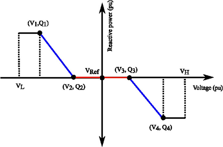
FIGURE 1. IEEE standard 1547-2018 V-Var Mode (pho, 2020).
In order to realise the reactive power control in smart converters, the fundamental concept of the power capability curve of the power converter needs to be precise. Figure 2 shows the capability curve and the relationship of converter size with the reactive power.
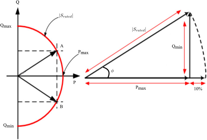
FIGURE 2. Power capability curve of smart converter (Kabiri et al., 2014).
In algorithm 1, the overall process of Volt-Var control (VVC) mode in a converter is represented. For all converters in the network, Volt-Var is implemented at the same time. To bring the system under similar consideration, the Volt-Var settings for all converters are considered the same. In algorithm 1, n is the total number of buses. m is the total number of buses with DER integration. k is the total number of load buses. The active and reactive power consumption of the load on the bus k at a particular moment in the simulation time t is represented by
The block diagram representation of the real-time VVC is presented in Figure 3. Typhoon HIL control centre, the Volt-Var control centre, and the Typhoon HIL and OpenDSS co-simulation are the main components for obtaining the real-time Volt-Var control using the propsed method. The Typhoon HIL control centre consists of various Python-based programmes to execute the co-simulation between the OpenDSS and the real-time simulator. The control centre also communicates with the Volt-Var control centre using the Python-based programme. The Volt-Var control centre communicates with OpenDSS to implement Algorithm 1 from the information obtained from the Typhoon HIL control centre and OpenDSS.
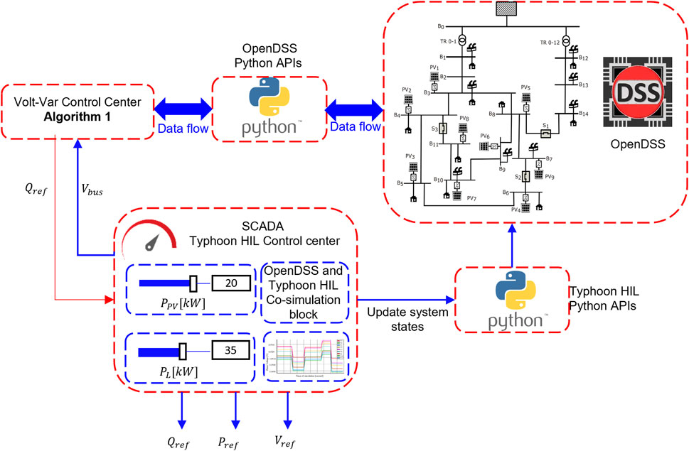
FIGURE 3. Co-simulation between OpenDSS and Typhoon HIL for real-time Volt-Var control.
3 Detailed modelling of grid forming converters
DERs like wind power plants and solar photovoltaics, are not directly connected to the grid (Wen et al., 2022). Generally, converters are used to connect them to the grid. An appropriate control design is an important aspect to connect the DERs efficiently. The control algorithms are anticipated to establish active power and reactive power from the DERs based on the scope of interconnection. The literature has several control measures that have been suggested (Ansari et al., 2021). The degree of integration of RESs into the network should also be taken into account when choosing the appropriate control mechanisms. Synchronous generators in the network can manage unstable power dynamics when there are fewer DERS interconnected. However, these generators are not able to manage such system dynamics and maintain system stability in converter-dominated systems, as converter-based DERs lack damping or spinning inertia (Van Wesenbeeck et al., 2009). Researchers are becoming more interested in the idea of virtual synchronous machines (VSMs) (Zhong and Weiss, 2010) as a potential solution to this problem. Physically, VSMs are power electronics converters that can provide the grid with virtual inertia and damping (Azuara-Grande et al., 2022). This work uses the grid-forming synchronverter (Zhong and Weiss, 2010; Zhong, 2016) created as a voltage source for real-time reactive power regulation. The grid forming converter has the ability to maintain angle and voltage at the coupling point. Are therefore thought to be appropriate for DER-enriched distribution networks Awal et al. (2020).
Control of the synchronverter to regulate active and reactive power is governed by a mathematical model of the synchronous generator (Zhong et al., 2015). As the main focus of this paper is to implement the real-time control using the developed CPCS framework, this paper implements the control similar to (Zhong et al., 2015). Assume that the stator windings are placed in slots around the uniform air gap in a synchronous generator and that the stator winding has a self-inductance of L, mutual inductance of M, and resistance Rs characterise the stator winding. The electromagnetic flux (Φ) produced by the stator winding and the current (i) flowing through the winding can be represented by Eq. 2.
The phase shift between the phases differs by
The phase terminal voltage
where, Ls = L+M and
The relative location of the electrical rotor axis and the magnetic field axis in a synchronous generator is fixed under normal operating conditions. However, any disturbance causes the rotor to decelerate or accelerate, reducing or increasing the rotor angle θ. The swing equation (Grainger and Stevenson, 1994) describes a relative motion of the rotor for synchronously rotating air gap. The swing equation is given by Eq. 6.
Where J is the moment of inertia of all the rotating parts, D is the damping factor, Tm is the mechanical torque, and Te is the electromagnetic torque. The electromagnetic torque is given by Eq. 7.
where ⟨⋅, ⋅⟩ denotes the inner product in
The controller block diagram is placed within the overall methodology block diagram 4. Inside the block diagram, the controller is represented by the mathematical model described above. The controller takes Pref and Qref as input and provides Pe and Qe as electrical outputs. I is the current that flows into the grid from the synchronverter. I is given by Eq. (2). Pref and Qref are obtained from the controlling and monitoring system developed in SCADA of the proposed cyber-physical testbed for real-time Volt-Var control. Pe and Qe are sent back to the converters in the distribution network through the SCADA. A detailed description of the signal flow to and from the controller is described in Section 4.
4 Proposed real-time Volt-Var control
For monitoring and controlling the distribution networks, a number of crucial components are needed to implement the real-time application (Borlase, 2017). One of the most fundamental needs is a tool to calculate three-phase unbalanced power flow. Other factors include the control system and its implications for supervisory control and data acquisition (SCADA). Remotely controlled equipment infrastructure, improved real-time metering, and communication infrastructure are also essential. Some of the requirements are developed in the cybernetic layer and some of them in the physical layer. The cyber-physical co-simulation (CPCS) framework for real-time Volt-Var control is made up of two layers 1) the cybernetic layer and 2) the physical layer. The cybernetic layer consists of monitoring and controlling components, software to interface with the physical layer, and software to communicate with the distribution system simulator (OpenDSS in this instance). For simplicity, all the software of the cybernetic layer is executed on the host PC. All controllable hardware, both virtual and actual, is part of the physical layer.
The cybernetic layer is the central core of the CPCS framework for real-time Volt-Var control. The host PC contains the cybernetic layer. Additionally, the host PC has the software required to administer and model the real-time digital simulator. The main purpose of the proposed CPCS framework for Volt-Var control is to simulate an entire distribution network and implement real-time Volt-Var control. As a result, the proposed CPCS framework is equipped with measuring and monitoring devices to obtain the necessary parameters, such as voltage magnitudes in the network. To create variation in DER generation and load demand in real-time, different sliders are placed in SCADA. The change in SCADA is represented in the distribution network by a signal processing system designed within the programme. After the co-simulation, the network experiences a change in the operating condition. With a change in the network operating condition, the SCADA monitoring system triggers the Volt-Var controller to obtain the reactive power references for the GFC. The voltage profile resulting after the application of Volt-Var Control can be observed in real-time. A monitoring and control system created in Typhoon HIL SCADA may be used to dynamically adjust the active power production and loads. A graphical user interface (GUI) is the monitoring and control system of a CPCS framework for real-time Volt-Var Control, and it enables real-time visualisation and control of the simulation. The GUI is specifically designed to show the signals produced by the measurement devices linked to the test system during real-time simulation. The GUI also shows the current condition of the bus voltages visually or digitally. This study uses the Typhoon HIL SCADA system to construct the GUI. Using the Python API, the HIL SCADA communicates with both the cybernetic and physical layers. The true simulation happens at the physical layer. The physical layer in this investigation was HIL 604 from Typhoon HIL Inc. The HIL 604 has eight processing cores, two digital I/O channels, and two analogue I/O channels. It also has two Advanced RISC Machine (ARM) cores.
The general process of implementing the real-time Volt-Var control is shown in Figure 4. Firstly, the test distribution system is modelled in OpenDSS. DERs are placed on the distribution network in the OpenDSS model. The OpenDSS modules are executed via Python API. A Python programme is written inside the Typhoon HIL SCADAIL to interface with OpenDSS. In a Typhoon HIL schematic editor, the grid-forming converter is modelled according to the mathematical model as described in Section 3. The communication interface between the SCADA and the Typhoon HIL real-time simulator is developed using signal processing components available in Typhoon HIL and the Python API of Typhoon HIL. The SCADA system continuously monitors the node voltage of the network and, using the information of the voltage, the Volt-Var controller is designed in the cyber layer. The detailed algorithm for the Volt-Var control for all connected GFCs is presented in Section 2. The reference active and reactive power after the application of the Volt-Var controller is then sent to the GFC. The GFC controller is designed in such a way as to track the reference active and reactive power. The electrical power output of the GFC is then fed to the distribution system. The model can interact with the SCADA and the Typhoon HIL real-time simulator using the signal processing blocks developed in the Typhoon HIL SCADA. The SCADA also consists of a Python programme to get the signals from OpenDSS, process the signal, and display them in real-time. SCADA is equipped with different sliders (to change the load and generation) to send the real-time signal to the OpenDSS. The signals exchanged between the cyber and physical layers are Pref, Qref, Pe, Qe, Vgrid. The exchange of information is done with the help of the signal processing block available in the typhoon HIL and a programme written in Python. The real-time simulation is executed at a fixed time step (1.00 s), which is the maximum allowable execution time of Typhoon HIL. After each time step, the process is repeated until the user stops the simulation.
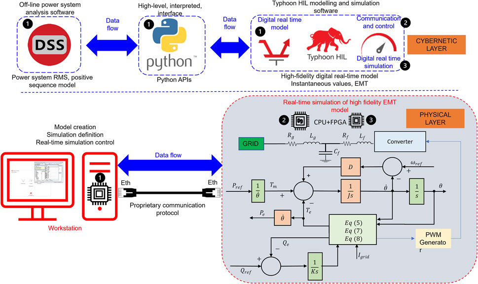
FIGURE 4. Overall methodology of proposed real-time Volt-Var control using cyber-physical co-simulation framework.
5 Real-time simulation studies
This section demonstrates the proposed real-time simulation analysis of the proposed real-time Volt-Var control. The study was performed in the Digital Energy Systems Laboratory (DIgEnSys-Lab). The DIgEnSys-Lab features physical equipment for real-time monitoring and control (for more information, see https://fglongattlab.fglongatt.org). The following subsections go through each component of the simulation research. In this research, Typhoon HIL 604, OpenDSS and Python are used for cyber-physical co-simulation (CPCS) for real-time Volt-Var control.
5.1 Test system
European MV distribution network can be used for DER integration studies (Acosta et al., 2021). Therefore, in this study, the European MV distribution network developed by the CIGRE Task Force C6.04 in “Benchmark Systems for Network Integration of Renewable and Distribution Energy Resources” (Barsali et al., 2014) is considered. The network is symmetric and balanced. The test system is shown in Figure 5. The network can be operated in radial or meshed topology by turning on or off the switches S1, S2, and S3. However, in this analysis, all switches are considered closed. To study the effectiveness of real-time Volt-Var control in GFC in this case and to represent the dominance of GFC, the wind power plant on bus B7 considered in the original study is replaced by a DER source. In this study, PVs are considered as DERs.
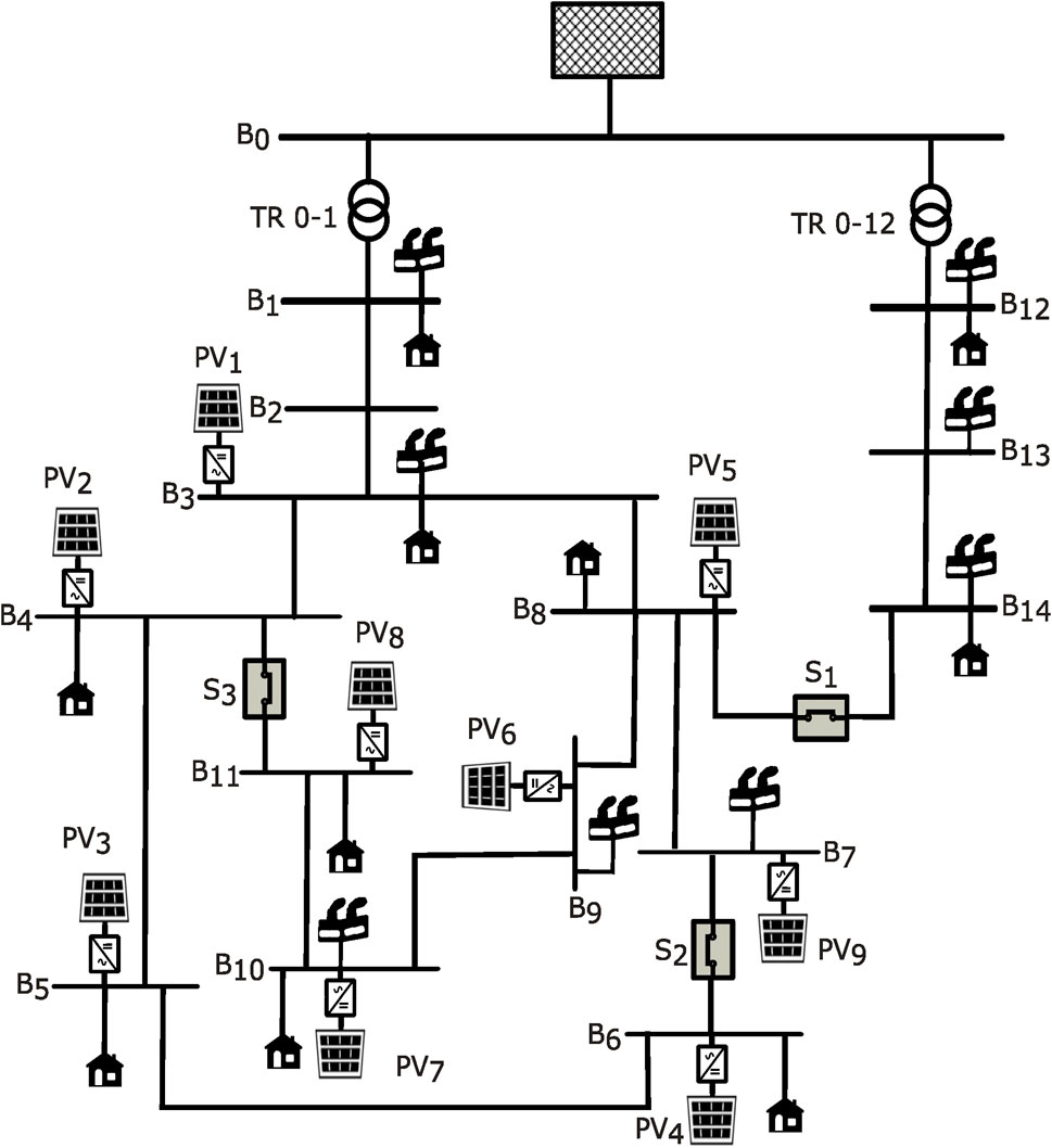
FIGURE 5. Layout of CIGRE network with loads and DERs (Barsali et al., 2014).
Table 1 shows the PV ratings considered in this study. In this study, the size of the photovoltaics and the load are modified according to the hosting capacity and the calculation of the spare load capacity performed for the same distribution network. For simplicity, constant impedance loads are considered in this analysis. The main aim of this study is to incorporate the proposed cyber-physical co-simulation framework for control application, even though constant power loads have destabilising effects on volt-volt control methods, the effect is not considered in this study. Tables 2, 3 are the values of residential and commercial loads considered in this study. Network information is taken as in the original CIGRE test network.
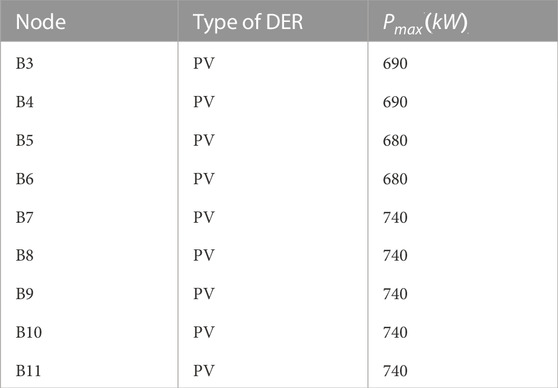
TABLE 1. MV distribution network benchmark application: parameters of PV units (Barsali et al., 2014).
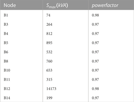
TABLE 2. MV distribution network benchmark application: Parameters of residential load.
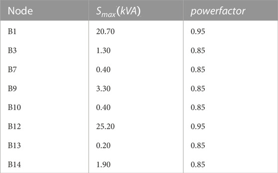
TABLE 3. MV distribution network benchmark application: Parameters of commercial load.
The controller parameters considered in this study are given in Table 4.
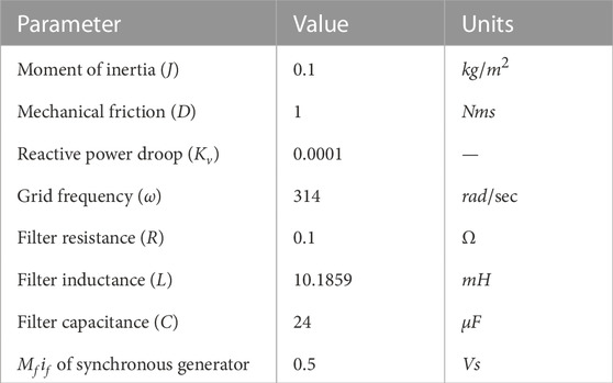
TABLE 4. Parameters of controller of grid forming converter (Zhong et al., 2015).
5.2 Real-time simulation results and discussion
A case study is considered to check the effectiveness of the proposed real-time Volt-Var Control (VVC) in the distribution network. In this case study, active power generation from PVs and some residential loads is dynamically changed during the real-time simulation of the SCADA panel developed in this study. The power from PV and the load can be changed in real time by changing the value of the slider widget in THIL SCADA, developed for this specific purpose. The real-time simulation is executed at an execution time of 1.00 s. The proposed VVC and all signal processing are completed within the time frame of each iteration.
The change in active power from the PVs and the loads from the SCADA modify the operating condition of the distribution network by CPCS between OpenDSS and Typhoon HIL. The loads and active power of PV are randomly changed during the real-time simulation in this study. These values are stored in a database during a real-time simulation. After each execution time, the corresponding voltage profile of the distribution network is monitored through the monitoring system developed using advanced model-based system engineering tool chains of Typhoon HIL. Inside a Typhoon HIL, a Python-based programme activates the VVC and provides the reactive power references to manage uncertain voltage violations. This reactive power reference is passed to the grid-forming converter modelled inside the real-time simulator. The active and reactive power output of the converter is fed back to PV in the distribution network. This process is repeated until the end of the simulation. To consider the limitations of the Typhoon HIL configuration available in the laboratory, only four smart converters are designed in Typhoon HIL. For the rest of the PV in the network, the active power reference and the reactive power reference are fed directly to the PV in the distribution network. The real implementation of the power converters developed in THIL are PV1, PV3, PV6, and PV9 connected to B3, B5, B9, and B7, respectively. However, the active power reference is changed for all the PVs connected to the network to change the system’s dynamics. Figure 6 shows the active power reference and the active power generated by the converter. Active power references are obtained by randomly changing the sliders in SCADA.
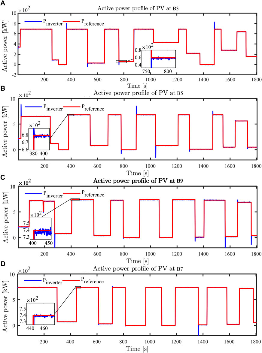
FIGURE 6. Active power profile of PV at (A) B3, (B) B5, (C) B9, and (D) B7.
Similarly, to make the real-time simulation more realistic, some of the residential loads in the distribution network are dynamically changed. Residential loads in B4, B5, B8, B10, and B12 are only changed in this study, and the rest of the loads are considered constant. However, it is possible to change all loads during a real-time simulation. The change in loads is exchanged with the distribution network model by a similar process as explained for the change in the active power reference of PVs. The load profile of residential loads in B4, B5, B8, B10, and B12 is shown in Figure 7. The load profile is obtained by changing the values randomly in real-time from the SCADA.
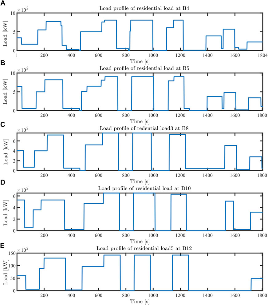
FIGURE 7. Load profile of residential load at (A) B4, (B) B5, (C) B8, (D) B10, and (E) B12.
The distribution network experiences changes in the voltage profile of the network with the change in the active power of the PVs and loads. In Figure 8B, it is observed that there are some instances where voltage violations are observed. This voltage profile is obtained by offline co-simulation with the values stored during real-time simulation to make a comparative analysis.
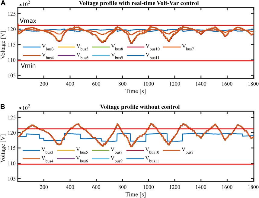
FIGURE 8. Voltage profile comparison of the CIGRE network (A) with real-time Volt-Var control in PV (B) with fixed power factor in PV.
However, during real-time Volt-Var control, as soon as voltage violations are observed in the network, the real-time Volt-Var controller dispatches the required reactive power to mitigate these voltage violations. With this reactive power from the converter, voltage violations are supposed to be mitigated. The voltage profile obtained during the real-time simulation is depicted in Figure 8A. It is observed that there are no voltage violations during the real-time simulation. This analysis shows the effectiveness of the real-time Volt-Var controller to mitigate voltage violations. The real-time Volt-Var controller is able to mitigate voltage violation issues that were observed with the same PV and load profile on the network.
The reference reactive power and the output reactive power from the PV1, PV3, PV6, and PV9 converters are shown in Figure 9. Reactive power references are sent from the real-time Volt-Var controller based on the voltage of the network at that instant. The GFC controller tracks the reactive power reference. This electrical power is fed to the PV in the distribution network. According to the standard, the positive reactive power is considered as a capacitive reactive power support and the negative reactive power as inductive. Voltage violations below the prescribed limit are supported by capacitive reactive power, while voltage violations above the prescribed limit are supported by inductive reactive power. The reactive power reference profile is obtained from the Volt-Var setting as described in Section 2.
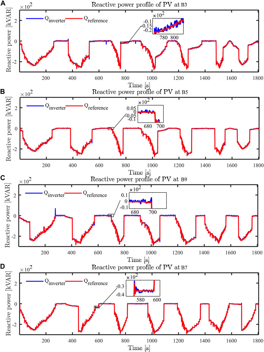
FIGURE 9. Reactive power profile of PV at (A) B3, (B) B5, (C) B9, and (D) B7.
5.3 Computational analysis
The computational efficiency of the cyber-physical co-simulation framework is highly dependent on the executable model in the physical layer. This also differs according to the application of the cyber-physical system. The authors in (Tzanis et al., 2018) analyse the computational part of the real-time transient behaviour of a single full-bridge inverter with FPGA hardware resources in a cyber-physical system of a modern distribution grid. Only a few component analyses are presented, for example, the number of logical function blocks (33% of available resources), the number of input output blocks (29% of available resources), the number of digital signal processing blocks (4% of available resources), and a computational time of 0.126 μS. The detailed description of the computational analysis also differs from that of the real-time simulator considered for the developed CPCS. Table 5 shows the detailed computational analysis of the proposed CPCS.
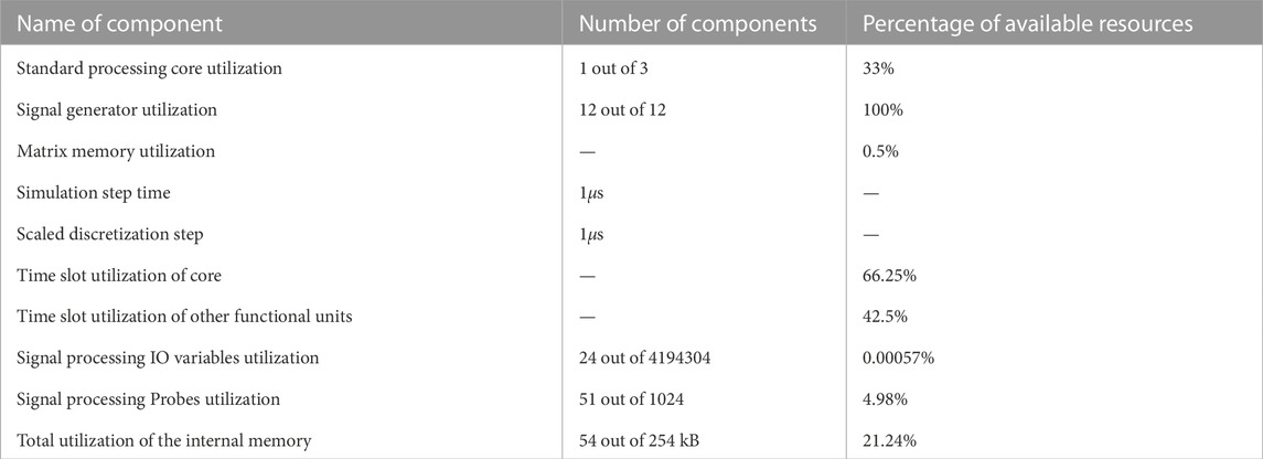
TABLE 5. Computational analysis of proposed CPCS.
6 Discussion and conclusion
In this study, a fundamental framework for real-time Volt-Var control is designed in a DER-enriched distribution network to address voltage violations caused by increased penetration of DERs. This study also shows how effectively the suggested framework for real-time cyber-physical co-simulation (CPCS) can handle voltage violations in DER-enriched distribution networks. The suggested method is more adaptable for implementation on any sort of distribution network since the distribution network was modelled on an open source distribution network solver called OpenDSS. The controller for the grid-forming converter modelled in Typhoon HIL tracks the active power reference from the SCADA and the reactive power reference from the Volt Var controller. Reactive power references are computed in real-time by the Volt Var controller to mitigate voltage violations. In the Typhoon HIL, an SCADA is created to perform CPCS and real-time Volt Var control. Taking into account the alteration in the generation profiles of DERs and the consumption profiles of loads, a scenario of voltage violations was developed. The effectiveness of the real-time VVC suggested to mitigate voltage violations is shown by real-time simulations. This study broadens the multidimensional horizon for real-time simulation studies on a CPCS between Typhoon HIL and OpenDSS. The framework developed in this study can be implemented on any type of distribution network, whether single-phase or multi-phase, balanced or unbalanced.
The model-based system engineering tool chains of Typhoon HIL are used in this work to process signals and exchange information between the cyber and physical layers. However, the application of C37.118 or IEC61850 communication protocol is left for future work.
Data availability statement
The original contributions presented in the study are included in the article/Supplementary Material, further inquiries can be directed to the corresponding author.
Author contributions
RW, PS, and FG-L contributed to the conception and design of the study. RW and FG-L developed the methodology and software validation. RW performed the simulation studies. RW wrote the first draft of the manuscript. PS, CS, MA, and FG-L review the manuscript. All authors contributed to the revision of the manuscript, read and approved the submitted version.
Acknowledgments
The authors are very grateful to the Arctic Centre for Sustainable Energy (ARC) (project number 740108), The Arctic University of Norway, Norway, for providing an opportunity for Raju to visit and work at DIgEnSys-Lab. The authors thank UiT The Arctic University of Norway for covering the publishing cost. The authors also acknowledge the technical support provided by the Typhoon HIL and OpenDSS teams.
Conflict of interest
The authors declare that the research was conducted in the absence of any commercial or financial relationship that could be construed as a potential conflict of interest.
Publisher’s note
All claims expressed in this article are solely those of the authors and do not necessarily represent those of their affiliated organizations, or those of the publisher, the editors and the reviewers. Any product that may be evaluated in this article, or claim that may be made by its manufacturer, is not guaranteed or endorsed by the publisher.
References
Acosta, M. N., Gonzalez-Longatt, F., Andrade, M. A., and Rueda Torres, J. (2021). “Optimal reactive power control of smart inverters: Vestfold and telemark regional network,” in Proceeding of the 2021 IEEE Madrid PowerTech, Madrid, Spain, July 2021 (IEEE), 1–6. doi:10.1109/PowerTech46648.2021.9494911
Amendment to IEEE Std 1547-2018 (2020). “IEEE standard for interconnection and interoperability of distributed energy resources with associated Electric Power Systems Interfaces--Amendment 1: To Provide More Flexibility for Adoption of Abnormal Operating Performance Category III,” in IEEE Std 1547a-2020 (Amendment to IEEE Std 1547-2018), April 15, 2020 (IEEE), 1–16. doi:10.1109/IEEESTD.2020.9069495
Anastasiadis, A. G., Kondylis, G. P., and Vokas, G. A. (2019). Effect of augmented distributed generation in distribution networks. Energy Rep. 6, 177–187. doi:10.1016/j.egyr.2019.10.036
Ansari, S., Chandel, A., and Tariq, M. (2021). A comprehensive review on power converters control and control strategies of ac/dc microgrid. IEEE Access 9, 17998–18015. doi:10.1109/ACCESS.2020.3020035
Awal, M. A., Yu, H., Lukic, S., and Husain, I. (2020). Droop and oscillator based grid-forming converter controls: A comparative performance analysis. Front. Energy Res. 8, 168. doi:10.3389/fenrg.2020.00168
Azuara-Grande, L. S., Gonzalez-Longatt, F., Tricarico, G., Wagle, R., Arnaltes, S., and Granizo, R. (2022). “Real-time implementation of two grid-forming power converter controls to emulate synchronous generators,” in Proceeding of the 2022 IEEE Biennial Congress of Argentina (ARGENCON), San Juan, Argentina, September 2022 (IEEE), 1–6. doi:10.1109/ARGENCON55245.2022.9940076
Barsali, S., et al. (2014). Benchmark systems for network integration of renewable and distributed energy resources. International Council on Large Electric Systems Paris France.
Bollen, M. H., Das, R., Djokic, S., Ciufo, P., Meyer, J., Rönnberg, S. K., et al. (2017). Power quality concerns in implementing smart distribution-grid applications. IEEE Trans. Smart Grid 8, 391–399. doi:10.1109/TSG.2016.2596788
Cao, G., Gu, W., Gu, C., Sheng, W., Pan, J., andLijing Sun, R. L., et al. (2019). Real-time cyber-physical system co-simulation testbed for microgrids control. IET Cyber-Physical Syst. Theory & Appl. 4 (7), 38–45. doi:10.1049/iet-cps.2018.5040
Ceylan, O., Paudyal, S., and Pisica, I. (2021). Nodal sensitivity-based smart inverter control for voltage regulation in distribution feeder. IEEE J. Photovoltaics 11, 1105–1113. doi:10.1109/jphotov.2021.3070416
Chen, S., Liu, P., and Li, Z. (2020). Low carbon transition pathway of power sector with high penetration of renewable energy. Renew. Sustain. Energy Rev. 130, 109985. doi:10.1016/j.rser.2020.109985
Cintuglu, M. H., Mohammed, O. A., Akkaya, K., and Uluagac, A. S. (2016). A survey on smart grid cyber-physical system testbeds. IEEE Commun. Surv. Tutorials 19, 446–464. doi:10.1109/comst.2016.2627399
Dai, Q., and Shi, L. (2020). “A game-theoretic analysis of cyber attack-mitigation in centralized feeder automation system,” in Proceeding of the 2020 IEEE Power & Energy Society General Meeting (PESGM), Montreal, QC, Canada, August 2020 (IEEE), 1–5. doi:10.1109/PESGM41954.2020.9281583
Dai, Q., Shi, L., and Ni, Y. (2019). Risk assessment for cyberattack in active distribution systems considering the role of feeder automation. IEEE Trans. Power Syst. 34, 3230–3240. doi:10.1109/TPWRS.2019.2899983
DNV GL (2020). Energy Transition Outlook 2020 - a global and regional forecast to 2050. Dnv Gl Energy Transition Outlook, 306.
Gao, B., and Shi, L. (2020). Modeling an attack-mitigation dynamic game-theoretic scheme for security vulnerability analysis in a cyber-physical power system. IEEE Access 8, 30322–30331. doi:10.1109/ACCESS.2020.2973030
Gao, D. W., Muljadi, E., Tian, T., and Miller, M. (2017). Software comparison for renewable energy deployment in a distribution network. Tech. rep., Golden, CO (United States): National Renewable Energy Lab.
Ghosh, S., Rahman, S., and Pipattanasomporn, M. (2016). Distribution voltage regulation through active power curtailment with pv inverters and solar generation forecasts. IEEE Trans. Sustain. Energy 8, 13–22. doi:10.1109/tste.2016.2577559
Guo, S., and Shi, L. (2020). “Robust optimal dispatch of power grid considering wind/pv power uncertainties,” in Proceeding of the 2020 IEEE 4th Conference on Energy Internet and Energy System Integration (EI2), Wuhan, China, October 2020 (IEEE), 1401–1406. doi:10.1109/EI250167.2020.9346740
Hou, J., Lei, S., Yin, W., Peng, C., and Hou, Y. (2020). “Optimal cyber defense strategy of high-voltage dc systems for frequency deviation mitigation,” in Proceeding of the 2020 IEEE International Conference on Communications, Control, and Computing Technologies for Smart Grids (SmartGridComm), Tempe, AZ, USA, November 2020 (IEEE), 1–5. doi:10.1109/SmartGridComm47815.2020.9302983
Hu, P., Jiang, K., Ji, X., Tan, D., Liu, D., Cao, K., et al. (2022). A novel grid-forming strategy for voltage-source controlled PV under nearly 100% renewable electricity. Front. Energy Res. 10. doi:10.3389/fenrg.2022.915763
Kabiri, R., Holmes, D., and McGrath, B. (2014). “The influence of pv inverter reactive power injection on grid voltage regulation,” in Proceeding of the 2014 IEEE 5th International Symposium on Power Electronics for Distributed Generation Systems (PEDG), Galway, Ireland, June 2014 (IEEE), 1–8.
Kim, W., Song, S., and Jang, G. (2020). Droop control strategy of utility-scale photovoltaic systems using adaptive dead band. Appl. Sci. 10, 8032. doi:10.3390/app10228032
Ku, T., Lin, C., Chen, C., Hsu, C., Hsieh, W., and Hsieh, S. (2015). “Coordination control of pv inverters for load transfer operation of distribution feeders with high penetration of pv installation,” in Proceeding of the 2015 IEEE/IAS 51st Industrial & Commercial Power Systems Technical Conference (I&CPS), Calgary, AB, Canada, May 2015 (IEEE), 1–8.
Langsdorf, S. (2011). Eu energy policy: From the ecsc to the energy roadmap 2050. Brussels, Belgium: Green European Foundation.
Li, P., Ji, J., Ji, H., Jian, J., Ding, F., Wu, J., et al. (2020). Mpc-based local voltage control strategy of dgs in active distribution networks. IEEE Trans. Sustain. Energy 11, 2911–2921. doi:10.1109/tste.2020.2981486
Liu, M. B., Canizares, C. A., and Huang, W. (2009). Reactive power and voltage control in distribution systems with limited switching operations. IEEE Trans. Power Syst. 24, 889–899. doi:10.1109/TPWRS.2009.2016362
Liu, W., Chen, S., Hou, Y., and Yang, Z. (2022). Trilevel mixed integer optimization for day-ahead spinning reserve management of electric vehicle aggregator with uncertainty. IEEE Trans. Smart Grid 13, 613–625. doi:10.1109/TSG.2021.3113720
Mahmud, N., and Zahedi, A. (2016). Review of control strategies for voltage regulation of the smart distribution network with high penetration of renewable distributed generation. Renew. Sustain. Energy Rev. 64, 582–595. doi:10.1016/j.rser.2016.06.030
Mihal, P., Schvarcbacher, M., Rossi, B., and Pitner, T. (2022). Smart grids co-simulations: Survey & research directions. Sustain. Comput. Inf. Syst. 35, 100726. doi:10.1016/j.suscom.2022.100726
Mokhtari, G., Ghosh, A., Nourbakhsh, G., and Ledwich, G. (2013). Smart robust resources control in lv network to deal with voltage rise issue. IEEE Trans. Sustain. Energy 4, 1043–1050. doi:10.1109/TSTE.2013.2265100
Molina-García, Á., Mastromauro, R. A., García-Sánchez, T., Pugliese, S., Liserre, M., and Stasi, S. (2016). Reactive power flow control for pv inverters voltage support in lv distribution networks. IEEE Trans. Smart Grid 8, 447–456. doi:10.1109/tsg.2016.2625314
Standard, B. (2007). Voltage characteristics of electricity supplied by public distribution networks. BS EN.
Sun, C.-C., Hong, J., and Liu, C.-C. (2015). “A co-simulation environment for integrated cyber and power systems,” in Proceeding of the 2015 IEEE International Conference on Smart Grid Communications (SmartGridComm), Miami, FL, USA, November 2015 (IEEE), 133–138. doi:10.1109/SmartGridComm.2015.7436289
Tang, Z., Hill, D. J., and Liu, T. (2020). Distributed coordinated reactive power control for voltage regulation in distribution networks. IEEE Trans. Smart Grid 12, 312–323. doi:10.1109/tsg.2020.3018633
Tzanis, N., Andriopoulos, N., Proiskos, G., Birbas, M., Birbas, A., and Housos, E. (2018). “Computationally efficient representation of energy grid-cyber physical system,” in Proceeding of the 2018 IEEE Industrial Cyber-Physical Systems (ICPS), St. Petersburg, Russia, May 2018 (IEEE), 679–683. doi:10.1109/ICPHYS.2018.8390789
van der Meer, A., Palensky, P., Heussen, K., Morales Bondy, D., Gehrke, O., Steinbrinki, C., et al. (2017). “Cyber-physical energy systems modeling, test specification, and co-simulation based testing,” in Proceeding of the 2017 Workshop on Modeling and Simulation of Cyber-Physical Energy Systems (MSCPES), Pittsburgh, PA, USA, April 2017 (IEEE), 1–9. doi:10.1109/MSCPES.2017.8064528
Van Wesenbeeck, M., De Haan, S., Varela, P., and Visscher, K. (2009). “Grid tied converter with virtual kinetic storage,” in Proceeding of the 2009 IEEE Bucharest PowerTech, Bucharest, Romania, June 2009 (IEEE), 1–7.
Venkataramanan, V., Srivastava, A., and Hahn, A. (2016). “Real-time co-simulation testbed for microgrid cyber-physical analysis,” in Proceeding of the 2016 Workshop on Modeling and Simulation of Cyber-Physical Energy Systems (MSCPES), Vienna, Austria, April 2016 (IEEE), 1–6. doi:10.1109/MSCPES.2016.7480220
Wagle, R., Sharma, P., Sharma, C., Gjengedal, T., and Pradhan, C. (2021). Bio-inspired hybrid bfoa-pso algorithm-based reactive power controller in a standalone wind-diesel power system. Int. Trans. Electr. Energy Syst. 31, e12778. doi:10.1002/2050-7038.12778
Wagle, R., Tricarico, G., Sharma, P., Sharma, C., Reuda, J. L., and Gonzalez-Longatt, F. (2022). “Cyber-physical Co-simulation testbed for real-time reactive power control in smart distribution network,” in Proceeding of the 2022 IEEE Innovative Smart Grid Technologies - Asia (ISGT ASIA), November 2022.
Wang, L., Yan, R., and Saha, T. K. (2019). Voltage regulation challenges with unbalanced pv integration in low voltage distribution systems and the corresponding solution. Appl. Energy 256, 113927. doi:10.1016/j.apenergy.2019.113927
Wang, Z., Qi, D., Mei, J., Li, Z., Wan, K., and Zhang, J. (2021). Real-time controller hardware-in-the-loop co-simulation testbed for cooperative control strategy for cyber-physical power system. Glob. Energy Interconnect. 4, 214–224. doi:10.1016/j.gloei.2021.05.004
Wen, X., Wu, T., Jiang, H., Peng, J., and Wang, H. (2022). Mpc-based control strategy of pv grid connected inverter for damping power oscillations. Front. Energy Res. 10. doi:10.3389/fenrg.2022.968910
Zhang, Z., Ochoa, L. F., and Valverde, G. (2017). A novel voltage sensitivity approach for the decentralized control of dg plants. IEEE Trans. Power Syst. 33, 1566–1576. doi:10.1109/tpwrs.2017.2732443
Zhang, Z., Huang, S., Chen, Y., Li, B., and Mei, S. (2022a). Cyber-physical coordinated risk mitigation in smart grids based on attack-defense game. IEEE Trans. Power Syst. 37, 530–542. doi:10.1109/TPWRS.2021.3091616
Zhang, Z., Huang, S., Chen, Y., Li, B., and Mei, S. (2022b). Diversified software deployment for long-term risk mitigation in cyber-physical power systems. IEEE Trans. Power Syst. 37, 377–387. doi:10.1109/TPWRS.2021.3086681
Zhong, Q.-C., Ma, Z., Ming, W.-L., and Konstantopoulos, G. C. (2015). Grid-friendly wind power systems based on the synchronverter technology. Energy Convers. Manag. 89, 719–726. doi:10.1016/j.enconman.2014.10.027
Zhong, Q.-C. (2016). Virtual synchronous machines: A unified interface for grid integration. IEEE Power Electron. Mag. 3, 18–27. doi:10.1109/mpel.2016.2614906
Zhong, Q.-C., and Weiss, G. (2010). Synchronverters: Inverters that mimic synchronous generators. IEEE Trans. industrial Electron. 58, 1259–1267. doi:10.1109/tie.2010.2048839
Nomenclature
Abbreviations
DER Distributed energy resources
RES Renewable Energy Sources
DN Distribution Networks
GFC Grid Forming Converters
DSO Distribution System Operators
PV Photovoltaics
VRD Voltage regulating devices
OLTC On-load Tap Changing
VVC Volt-Var Control
LV Low voltage
CPCS Cyber-physical co-simulation
J Moment of inertia
D Mechanical friction
kv Reactive power droop
ω Grid frequency in rad/sec
Vk(t) Voltage phasor of bus k at time t
n Notation for bus
k Notation for load bus
m Notation for bus with DER integration
t Simulation time instant
Keywords: cyber-physical co-simulation, distribution network (DN), real-time control (RTC), grid forming converters, Typhoon HIL
Citation: Wagle R, Sharma P, Sharma C, Amin M and Gonzalez-Longatt F (2023) Real-time Volt-Var control of grid forming converters in DER-enriched distribution network. Front. Energy Res. 10:1054870. doi: 10.3389/fenrg.2022.1054870
Received: 27 September 2022; Accepted: 21 December 2022;
Published: 06 January 2023.
Edited by:
Yuzhang Lin, University of Massachusetts Lowell, United StatesReviewed by:
Srete Nikolovski, Josip Juraj Strossmayer University of Osijek, CroatiaVijay Babu Pamshetti, Chaitanya Bharathi Institute of Technology, India
Roy Mccann, University of Arkansas, United States
Copyright © 2023 Wagle, Sharma, Sharma, Amin and Gonzalez-Longatt. This is an open-access article distributed under the terms of the Creative Commons Attribution License (CC BY). The use, distribution or reproduction in other forums is permitted, provided the original author(s) and the copyright owner(s) are credited and that the original publication in this journal is cited, in accordance with accepted academic practice. No use, distribution or reproduction is permitted which does not comply with these terms.
*Correspondence: Pawan Sharma, cGF3YW4uc2hhcm1hQHVpdC5ubw==