 Srinivas Vanka
 Guosong Zeng2,3
 Francesca Maria Toma
- 1Department of Electrical Engineering and Computer Science, University of Michigan, Ann Arbor, MI, United States
- 2Department of Mechanical and Energy Engineering, Southern University of Science and Technology, Shenzhen, China
- 3Lawrence Berkeley National Laboratory, Chemical Sciences Division, Berkeley, CA, United States
- 4National Renewable Energy Laboratory, Chemistry and Nanoscience Center, Golden, CO, United States
Photoelectrochemical (PEC) water splitting, one of the most promising technologies for clean hydrogen generation, has drawn considerable attention over the past few decades. Achieving simultaneous highly efficient and stable unassisted PEC water splitting has been the “holy grail” in clean and renewable fuel generation. State-of-the-art photoelectrodes have shown relatively high efficiencies (∼10–20%). Still, their stability is limited due to photoelectrode chemical instability, electrolyte resistance, mass transfer issues, and an often unoptimized experimental setup. In this work, we present a framework and a set of protocols for conducting long-term stability experiments and further provide details on several critical factors such as light source calibration, choosing the right counter electrode, the configuration of the PEC cell, and photoelectrode sample preparation.
Introduction
An essential requirement for large-scale commercialization of PEC water splitting is the device’s durability against harsh electrolytes and under dark and different illumination intensities (Nandjou and Haussener, 2017; Kaneko et al., 2018). Due to the intermittency of solar radiation, the degradation of PEC devices is more accelerated than photovoltaic-electrolyzer devices (Shaner et al., 2016). Most of the high-efficiency semiconductors for PEC like Si (King et al., 2017; Ros et al., 2017) and III-V (Britto et al., 2016) are easily prone to chemical corrosion in the electrolyte (even under dark conditions). Si is easily oxidized to SiO2 in an aqueous solution (see Eq. 1) and forms a passivation layer on the Si surface, leading to a reduction (Kainthla et al., 1986).
III-V compounds, like GaAs, also go through corrosion reactions (see Eq. 2) due to either accumulation of a large surface hole concentration in the dark or light illumination, generating holes at the surface (Lewerenz, 2014). However, p-type III-arsenide semiconductors have shown remarkable stability under conditions where an As0 enriched surface provides passivation against corrosion (Young et al., 2016).
It was observed that N-terminated III-nitride nanostructures show virtually no chemical or photoelectrochemical corrosions when in contact with different electrolytes (Kibria et al., 2016; AlOtaibi et al., 2013; Vanka et al., 2018; Varadhan et al., 2017). Recent studies further revealed that the surfaces of such III-nitride nanostructures could be transformed to oxynitride, which leads to improved PEC performance, instead of degradation, under both one-sun and concentrated sunlight illumination (Zeng et al., 2021). Mi et al. reported one of the longest stability (>3,000 h) using an N-terminated multifunctional GaN nanowire protection scheme on Si photocathode (Vanka et al., 2019) and demonstrated durability under accelerated testing conditions (Zeng et al., 2021). Furthermore, Mi et al. demonstrated high stability of >100 h under a two-electrode experimental setup by utilizing single (STH ∼3%) (Wang et al., 2019) and double junction (STH ∼10%) (Vanka et al., 2020) InGaN/Si photocathodes. The underlying thermodynamic and kinetics of N-terminated (In)GaN nanostructures have been investigated in previous publications (Vanka et al., 2018; Zeng et al., 2021; Vanka et al., 2019; Vanka et al., 2020; He et al., 2019). The basic stability criteria for conduction band minimum
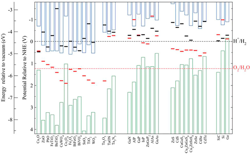
FIGURE 1. Calculated
Over the years, various protection schemes have been employed to enhance the stability of both photocathode and photoanode. The first approach (see Figure 2A) uses relatively thick metal oxide such as TiO2 (Ros et al., 2017; Yin et al., 2018), Al2O3 (Fan et al., 2015), or IrOx (Mei et al., 2014) as passivation layers for photocathode and photoanode. Even though the stability performance has improved substantially (Ros et al., 2017; Yin et al., 2018), the major issue is photocurrent loss due to poor charge carrier transfer kinetics and light absorption (Kaneko et al., 2018). In addition, these protective layers suffer from the presence of pinholes and often involve the use of additional deposition methods, such as ALD. Henceforth, during stability testing, these pinholes may act as catalytic degradation sites, which eventually leads to exposure of the photoelectrode to the electrolyte solution (Ros et al., 2017; Ben-Naim et al., 2020). Moon et al. observed in their stability experiments a decrease in photocurrent density and photovoltage for TiO2 protected III-V triple-junction solar cell photocathode (Moon et al., 2020). This performance degradation is due to the pinholes within the TiO2 layer, which erodes the top junction by allowing acidic electrolyte solution to dissolve the top junction and ultimately lead to delamination (Moon et al., 2020). The second approach (see Figure 2B) is to couple photoelectrode with a highly active catalyst, simultaneously improving stability and maintaining excellent reaction kinetics by efficiently extracting the photogenerated charge carriers (Nandjou and Haussener, 2017). One of the best stabilities achieved for a photocathode (∼60 days) with a relatively low photocurrent was reported by (King et al., 2017) using MoS2 on Si. Furthermore, high two-electrode stability for GaInAsP/GaAs with MoS2 protection under 2.6 suns illumination was reported recently (Ben-Naim et al., 2020). Interface losses and device complexity limit the performance of these devices. Although Si photoanode with NiCrOx/TiO2 protection (Shaner et al., 2015) showed high stability of ∼2,200 h, the photocurrent density is low, and the applied bias is greater than 1.23 V vs. NHE. Furthermore, hematite (α-Fe2O3) and bismuth vanadate (BiVO4) showed considerable stability (Dias et al., 2016; Kuang et al., 2016). The highest stability for nanostructured BiVO4 photoanode is >1,000 h using in-situ on-demand NiFe catalyst regeneration (Kuang et al., 2016). The primary issue with the metal-oxides is their low efficiencies because of the limitations in bulk transport of charge carriers and their wide bandgaps (Bae et al., 2017). Another exciting set of stable water splitting electrodes, which have gained attraction over the past decade, is self-healing/self-repairing catalysts. These (photo)electrodes/catalysts (Kanan and Nocera, 2008; Lutterman et al., 2009; Najafpour et al., 2015; Costentin and Nocera, 2017; Feng et al., 2021; Zeng et al., 2021) with the capacity to renew themselves during the water-splitting reaction require special protocols to evaluate the origins of their stability (Zeng et al., 2021). These protocols are beyond the scope of this work.
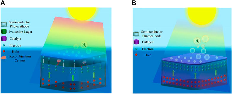
FIGURE 2. (A) Schematic showing the conventional thick protective layer with a catalyst on top of the light absorber. (B) Schematic showing the photoelectrode with catalyst layer as a protective layer. Reprinted (adapted) with permission from Vanka et al. (2019). Copyright 2019 Royal Society of Chemistry.
An important factor in the stability measurements is the configuration of the PEC cell. As discussed earlier, most of the photoelectrodes are relatively stable in a three-electrode configuration (Vanka et al., 2019), but few devices can reach 100 h under a two-electrode (zero-bias) PEC configuration (Ben-Naim et al., 2020; Vanka et al., 2020). Three-electrode PEC configuration accounts for only the stability of the working photoelectrode ignoring the performance of the counter electrode and the overall PEC system stability (Chen et al., 2011). On the other hand, the two-electrode PEC configuration gives the actual efficiency and durability under a realistic operating environment of the entire PEC cell, including both the working electrode and counter electrode (Hodes, 2012). Thus, it is crucial to perform the stability tests for the photoelectrodes in a two-electrode configuration under AM1.5G one-sun illumination to understand the real stability of the device. While this work focuses on continuous illumination over long durations, understanding PEC system durability under intermittent illumination is also essential for moving this technology from the bench to the field. Henceforth, it is pertinent to develop standard benchmarking stability protocols for the two and three-electrode configurations to permit researchers to evaluate the stability performance of the photoelectrodes against state-of-the-art devices and thereby accelerate the progress of PEC technology for large-scale deployment.
Procedures
Summary of Method
The stability experiments are essential to gain insights into the lifetime of the material. These experiments are conducted by recording the photocurrent against time under continuously applied bias in a two- or three-electrode configuration (Chen et al., 2011). As discussed earlier (see Figure 1), for most materials without protection schemes photocorrosion is thermodynamically favorable compared to HER or OER in an aqueous environment under illumination. The main cause is the accumulation of excess photogenerated charge carriers (holes or electrons), leading to side reactions (such as self-reduction or oxidation) (Su et al., 2017). Therefore, during stability experiments, it is recommended to quantify the evolved H2 and O2 to determine FE and STH (Chen et al., 2011). Photocorrosion is indicated by the degradation of photocurrent and/or LSV characteristics (such as onset potential, saturation photocurrent, and fill-factor) with time (Yang et al., 2019). The stability (or CA) experiments are conducted until the failure point, i.e., when the device photocurrent shows a significant drop at a given voltage. As shown in the flowchart (see Figure 3). The stability evaluation of the photoelectrode starts with either CV or LSV scans. These scans reveal whether the photoelectrode has favorable characteristics such as good photocurrent onset voltage, high photocurrent density, and high STH. After determining the photoelectrode photocurrent density vs. voltage (J-V) characteristics, the device’s CA response is measured in an aqueous electrolyte under AM1.5G one sun or concentrated sunlight illumination with no bias (0 V vs. counter electrode) in a two-electrode configuration. The J-V characteristics of the photoelectrode are periodically recorded during the stability experiments to evaluate whether the sample has degraded (reduction in photocurrent density or onset potential). Once the device reaches its catastrophic failure point, physical failure modes observed microscopically, and spectroscopic analysis of chemical transformations can be coupled with electrochemical procedures to inform the degradation mechanism.
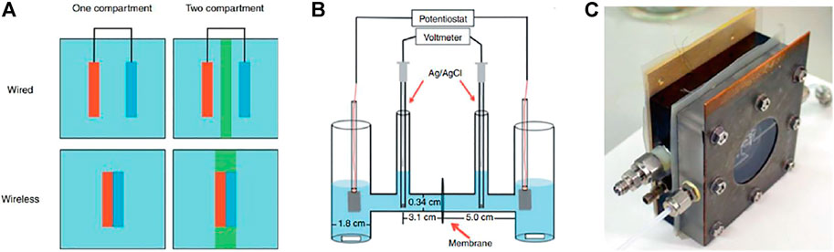
FIGURE 3. (A) Schematic illustration of wired and wireless configurations in one- and two-compartment PEC cells. Reprinted from Bosserez et al. (2015). Copyright 2012 EDP Sciences. (B) H-type glass chamber for PEC H2 and O2 evolution.Reprinted (adapted) with permission from Hernández-Pagán et al. (2012). Copyright 2012 Royal Society of Chemistry. (C) Dual compartment PEC cell with SEA, in-, and outlet connection. Reprinted from Bosserez et al. (2015). Copyright 2012 EDP Sciences.
Spectroscopy and electron microscopy provide further insight into the failure mechanism via structural analysis. Using these techniques, we can effectively compare the chemical transformation of the surface morphology before and after the photoelectrochemical reaction, while such chemical transformation either leads to catastrophic degradation or self-healing/self-improving (Kanan and Nocera, 2008; Malara et al., 2016; Toma et al., 2016; Zeng et al., 2021). Either way, the knowledge we obtain through structural analysis will provide feedback for further optimization of our device. Toma et al. (2016) employed EC-AFM to monitor the corrosion of BiVO4 and provide mechanistic insights into the chemical and photochemical instability of this material, which can be used to guide approaches for further improvement of BiVO4 photoanode. On the other hand, self-improving via chemical transformation can also be revealed by structural analysis. Zeng et al. (2021) reported that GaN can achieve self-improvement during HER by forming an ultrathin layer of gallium oxynitride, which led to lower overpotential, and higher charge transfer efficiency, and improved durability.
Equipment and Supplies
Electrochemical potentiostat- This is the essential equipment required to conduct J-V, Mott-Schottky, OCP, and CA experiments.
GC- A GC analyzer is required to detect hydrogen and oxygen gas products during PEC reactions. This equipment is also used to determine FE (Chen et al., 2011) and H2 gas evolution rates.
ICP-MS- ICP-MS is essential to determine any dissolved photoelectrode material, co-catalysts, and other metals/non-metals in electrolyte solution during the reaction (Deutsch et al., 2006).
SEM- This is one of the most used techniques to determine the morphological changes before and after stability experiments, with resolutions in the range of a few nanometers to sub-micrometer scale.
STEM- STEM is essential in analyzing nanometer, or atomic-scale feature sizes by using annular dark-field imaging, spectroscopic mapping by EDX, or EELS.
AFM- AFM scans provide nanometer resolution images of the top surface. For 2D films, AFM is sufficient to understand the surface degradation after stability experiments. However, for 1D nanostructures, this technique may be somewhat limited. Therefore, it is preferred to use SEM or STEM for 1D photoelectrodes. As mentioned earlier, in-situ AFM measurements such as EC-AFM and PC-AFM are instrumental in determining the nanoscale origin of photocurrent (Eichhorn et al., 2018; Nellist et al., 2018; Zeng et al., 2021).
XPS- This technique helps identify the elements, chemical states, and electronic structure of the photoelectrode material.
XRD- XRD scans provide critical information for structural changes of the photoelectrode materials, such as crystal structures, phases, defects, and strain distribution. Therefore, any changes in crystallinity of the material revealed by XRD scans can provide critical information regarding photocorrosion on the surfaces.
Reagents- Alkaline solution (potassium hydroxide, etc.), acid solution (sulfuric acid, etc.), and deionized water.
The essential protocols, based on the authors’ practical experience (Vanka et al., 2019; Zeng et al., 2021), needed for performing long term stability tests for >1,000 h are:
1. PEC cell design: The major parameters impacting the PEC cell performance include electrolyte solution/volume and the ionic path length (Hernández-Pagán et al., 2012). The PEC cells (or reactors) can be classified based on compartmentalization. As shown in Figure 3A, both wired and wireless electrode assembly configurations can be implemented in PEC cells comprising either a single or double compartment (Bosserez et al., 2015). A major limitation of single compartment PEC cells (see Figure 3A) is that evolving H2 and O2 gases are mixed in the same chamber, which leads to recombination reactions. These unwanted chemical reactions can be avoided by producing H2 and O2 in separate compartments using an H-cell (see Figure 3B). An important issue with unsealed PEC cells is the presence of atmospheric oxygen, which often produces deleterious effects on the water-splitting experiments (Hagfeldt et al., 1995). Using a dual compartment cell (see Figure 3C) with SEA helps seal off the sample from the environment and thus prevents air from entering the cell (Bosserez et al., 2015). In addition, this cell (see Figure 3C) has in- and outlet connections for feeding electrolyte solution and product collection, respectively. It is also essential to design proper compression cells to minimize bubbling and/or electrolyte resistance (Vanka et al., 2019). Furthermore, it is highly desirable that the cells have various aperture openings to properly test samples of different sizes.
2. Back contacts: Dissolution of epoxy accelerates photoelectrode degradation (Bae et al., 2019; Vanka et al., 2019), and dissolved silver may lead to dubious results in surface-sensitive XPS/ICP-MS analysis. Thus, it is essential to eliminate epoxy and silver paste by designing the compression cell with a metal pad, which allows the front side of the sample to be exposed to the electrolyte with the backside of the sample making electrical contact with the metal pad.
3. Electrolyte: In many cases, PEC experiments are conducted in near-neutral pH electrolyte solutions because of safety concerns and exacerbation of pinholes issues in the protection layers (as discussed earlier) under extremely acidic or alkaline electrolyte solutions (which are used in commercial electrolyzers) (Obata et al., 2020). However, the major disadvantage of using such pH-neutral conditions is the low concentration of H+/OH− in the electrolyte solutions. At such low concentrations, the reactants are rapidly consumed during CA experiments, and their refurbishment from the other electrolyte regions is hampered by mass transport limitations (Shinagawa and Takanabe, 2015a). This concentration imbalance leads to extra overpotentials in addition to kinetic overpotentials from catalysts (Shinagawa and Takanabe, 2015b; Ahmet et al., 2019). Furthermore, in an H-cell (see Figure 3B) with no buffer in the electrolyte solution, the generation of H2 and O2 gases in separate compartments leads to elevated and reduced pH, respectively. The local pH shift in the electrolyte solution during PCET reactions near the photoelectrode surface is a critical in factor determining its stability and efficiency. To mitigate this issue, buffer ions are added to the electrolyte solution. However, it is hard to eliminate the local pH gradient as the diffusion coefficients of buffer ions are smaller compared to those of H+/OH− ions (Shinagawa and Takanabe, 2016; Ahmet et al., 2019).
4. Counter electrode: The counter electrode plays a vital role in determining the stability of the entire PEC cell (Hodes, 2012). Some counter electrodes dissolve in the electrolyte during the reaction and can be plated on the photoelectrode, complicating PEC analysis (Choi et al., 2014). Thus, choosing stable counter electrodes and constructing a PEC compression cell with a membrane is important to prevent unwanted metal deposition on the photoelectrode surface.
Instrument or Method Calibration and Standardization
Light source intensity: The light source needs to be regularly recalibrated to maintain 100 mW/cm2 power density throughout the stability test (Chen et al., 2011), especially if it is not continuously measured over time.
Electrochemical potentiostat: It is quintessential to calibrate these instruments by following the vendor’s recommendations correctly to obtain reliable and consistent results.
Example of Pt-Decorated GaN/Si Photocathode Stability
Here we explain the three-electrode stability measurements of N-terminated GaN/Si photocathode considering the protocols mentioned earlier.
Step 1: From Figure 4, the first basic step is to calibrate the light source to 100 mW/cm2. Mi et al. used Si (bandgap ∼1.1 eV) reference cell to calibrate their light source for GaN/Si photocathode (Vanka et al., 2018).
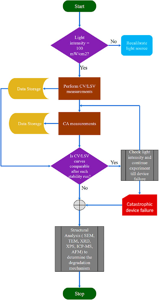
FIGURE 4. Flowchart illustrating the steps for performing long-term stability experiments.
Step 2: From Figures 5A,B, LSV scans show photocurrent onset voltage ∼0.56 V vs. NHE, high saturation photocurrent density ∼37 mA/cm2 and ABPE ∼11.9% (at 0.37 V vs. NHE) (Vanka et al., 2018; Vanka et al., 2019). As discussed earlier and shown in Figure 4, using the best sample for stability experiments in terms of high ABPE and excellent LSV characteristics is essential. The morphology of the 1D nanowires with co-catalyst nanoparticles is determined using STEM and SEM techniques (Vanka et al., 2018; Vanka et al., 2019). However, as discussed earlier, the AFM technique may be challenging for analyzing 1D nanowires and catalyst nanoparticles. Figure 5C shows the STEM image of the Pt decorated GaN/Si photocathode before CA experiments.
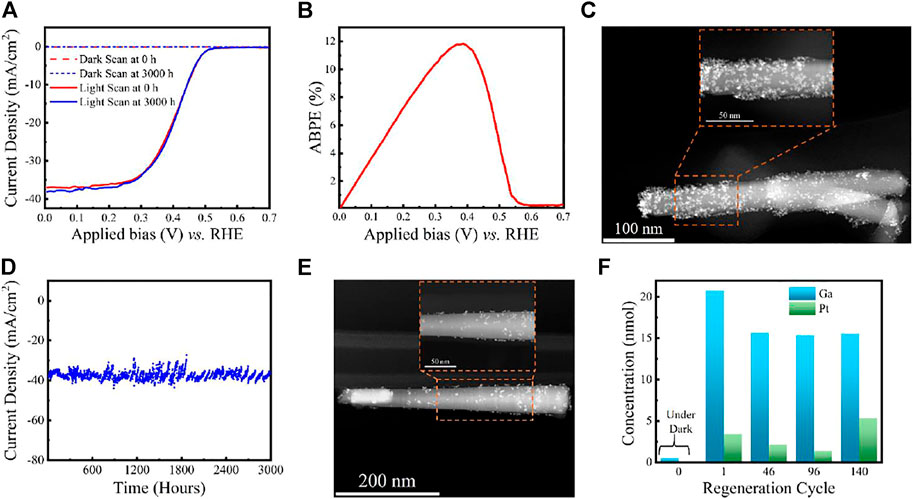
FIGURE 5. (A) LSV comparison of GaN/Si photocathode before and after 3,000 h stability experiments. (B) ABPE of Pt decorated GaN/Si photocathode before stability experiments in 0.5 M H2SO4 under AM 1.5G one-sun illumination. (C) STEM image of Pt decorated GaN nanowire before stability experiment. (D) Ultra-long term stability experiments using GaN/Si photocathode under continuous AM 1.5G one-sun illumination. (E) STEM image of Pt decorated GaN nanowire after 3,000 h stability experiments. (F) ICP-MS measurements of liquid samples at different runs during the experiment. Reprinted (adapted) with permission from Vanka et al. (2019). Copyright 2019 Royal Society of Chemistry.
Step 3: For the GaN/Si photocathode samples having ABPE >10%, CA experiments are performed in a three-electrode PEC configuration at 0 V vs. NHE in 0.5 M H2SO4 under AM 1.5G one sun (Vanka et al., 2018; Vanka et al., 2019). Zeng et al. demonstrated that the photocurrent density of GaN/Si photocathode does not degrade under concentrated sunlight (∼3 suns) illumination for 150 h (Zeng et al., 2021).
Step 4: LSV scans are measured after every run (each run is about 22–24 h duration). As shown in Figure 4, these scans need to be compared with the J-V characteristics before starting the stability experiments to determine whether to proceed further with the CA stability experiments or not (Vanka et al., 2019).
Step 5: The GaN/Si photocathode showed a decrement in photocurrent density, and J-V characteristics changed dramatically after 113 h (Vanka et al., 2018). By performing the structural analysis (STEM and SEM), the root cause of this degradation was attributed to the loss of Pt co-catalyst nanoparticles on the GaN nanowire surface (Vanka et al., 2018). Thus, to maintain the J-V and CA characteristics of GaN/Si photocathode over long periods of stability testing, it is pertinent to regenerate the co-catalyst regularly.
Step 6: Using a new sample (with the same J-V characteristics mentioned in step 2), the experiment is repeated from step 1. In this run, catalyst regeneration is implemented after approximately every 24 h to achieve long-term stability of >3,000 h (Vanka et al., 2019) (see Figure 5D) with no degradation in J-V performance after the experiments (see Figure 5A).
Step 7: The ultra-long stability (CA) experiments for GaN/Si photocathode are stopped after 3,000 h. From Figure 5E, STEM analysis reveals no apparent degradation in GaN nanowire dimensions and fewer Pt co-catalyst nanoparticles on the GaN surface than in Figure 5C (Vanka et al., 2019). Furthermore, ICP-MS (Figure 5F) shows that GaN remains stable throughout the CA experiments. Thus, the structural analysis and theoretical studies reveal that the stability of Pt decorated GaN/Si photocathode is limited by Pt nanoparticles rather than GaN/Si light absorber (Vanka et al., 2018; Vanka et al., 2019; Zeng et al., 2021).
Conclusion
This work provides an overview of the stability requirements of a photoelectrode and the pertinent need to develop standard protocols for long-term stability measurements in a two-electrode and three-electrode configuration. We have illustrated a framework to evaluate the stability of photoelectrode with an optimized experimental setup based on light source calibration, counter electrode optimization, PEC chamber, and sample preparation. The GaN/Si photoelectrode example showed how these protocols lead to proper stability measurements of the device and further improve the performance by understanding the degradation mechanism. We believe that for future stability studies, these benchmarking protocols can serve as valuable guidelines in accelerating the search for new photoelectrodes which can cut the “Gordian knot” of simultaneously achieving ultra-high stability (>10,000 h) and high efficiency (>15%).
Data Availability Statement
Publicly available datasets were analyzed in this study. This data can be found here: https://pubs.rsc.org/en/content/articlelanding/2019/ta/c9ta09926c#!divAbstract.
Author Contributions
SV and ZM conceived the study and wrote the manuscript. GZ, TD, and FT assisted in writing the article.
Author Disclaimer
The views expressed in the article do not necessarily represent the views of the DOE or the U.S. Government.
Conflict of Interest
Some IP related to this work has been licensed to NS Nanotech, Inc. and NX Fuels, Inc. (dba Carbon Fuels), which were co-founded by ZM. The University of Michigan and Mi have a financial interest in NS Nanotech and NX Fuels.
The remaining authors declare that the research was conducted in the absence of any commercial or financial relationships that could be construed as a potential conflict of interest.
Publisher’s Note
All claims expressed in this article are solely those of the authors and do not necessarily represent those of their affiliated organizations, or those of the publisher, the editors, and the reviewers. Any product that may be evaluated in this article, or claim that may be made by its manufacturer, is not guaranteed, or endorsed by the publisher.
Acknowledgments
The authors gratefully acknowledge research support from the HydroGEN Advanced Water Splitting Materials Consortium, established as part of the Energy Materials Network under the U. S. Department of Energy, under Contract Number DE-EE0008086 for the University of Michigan. This work was authored in part by the National Renewable Energy Laboratory, operated by Alliance for Sustainable Energy, LLC, for the U.S. Department of Energy under Contract Number DE-AC36-08GO28308. The U.S. Government retains and the publisher, by accepting the article for publication, acknowledges that the U.S. Government retains a nonexclusive, paid-up, irrevocable, worldwide license to publish or reproduce the published form of this work, or allow others to do so, for the U.S. Government purposes.
References
Ahmet, I. Y., Ma, Y., Jang, J.-W., Henschel, T., Stannowski, B., Lopes, T., et al. (2019). Demonstration of a 50 Cm2 BiVO4 Tandem Photoelectrochemical-Photovoltaic Water Splitting Device. Sustain. Energ. Fuels 3 (9), 2366–2379. doi:10.1039/c9se00246d
AlOtaibi, B., Nguyen, H. P. T., Zhao, S., Kibria, M. G., Fan, S., and Mi, Z. (2013). Highly Stable Photoelectrochemical Water Splitting and Hydrogen Generation Using a Double-Band InGaN/GaN Core/Shell Nanowire Photoanode. Nano Lett. 13 (9), 4356–4361. doi:10.1021/nl402156e
Bae, D., Seger, B., Hansen, O., Vesborg, P. C. K., and Chorkendorff, I. (2019). Durability Testing of Photoelectrochemical Hydrogen Production under Day/Night Light Cycled Conditions. Chemelectrochem 6 (1), 106–109. doi:10.1002/celc.201800918
Bae, D., Seger, B., Vesborg, P. C. K., Hansen, O., and Chorkendorff, I. (2017). Strategies for Stable Water Splitting via Protected Photoelectrodes. Chem. Soc. Rev. 46 (7), 1933–1954. doi:10.1039/c6cs00918b
Ben-Naim, M., Britto, R. J., Aldridge, C. W., Mow, R., Steiner, M. A., Nielander, A. C., et al. (2020). Addressing the Stability Gap in Photoelectrochemistry: Molybdenum Disulfide Protective Catalysts for Tandem III-V Unassisted Solar Water Splitting. ACS Energ. Lett. 5 (8), 2631–2640. doi:10.1021/acsenergylett.0c01132
Bosserez, T., Rongé, J., van Humbeeck, J., Haussener, S., and Martens, J. (2015). Design of Compact Photoelectrochemical Cells for Water Splitting. Oil Gas Sci. Technol. - Rev. IFP Energies Nouvelles 70 (5), 877–889. doi:10.2516/ogst/2015015
Britto, R. J., Benck, J. D., Young, J. L., Hahn, C., Deutsch, T. G., and Jaramillo, T. F. (2016). Molybdenum Disulfide as a Protection Layer and Catalyst for Gallium Indium Phosphide Solar Water Splitting Photocathodes. J. Phys. Chem. Lett. 7 (11), 2044–2049. doi:10.1021/acs.jpclett.6b00563
Butler, K. T., Dringoli, B. J., Zhou, L., Rao, P. M., Walsh, A., and Titova, L. V. (2016). Ultrafast Carrier Dynamics in BiVO4 Thin Film Photoanode Material: Interplay between Free Carriers, Trapped Carriers and Low-Frequency Lattice Vibrations. J. Mater. Chem. A. 4 (47), 18516–18523. doi:10.1039/c6ta07177e
Chen, S., and Wang, L.-W. (2012). Thermodynamic Oxidation and Reduction Potentials of Photocatalytic Semiconductors in Aqueous Solution. Chem. Mater. 24 (18), 3659–3666. doi:10.1021/cm302533s
Chen, Z., Jaramillo, T. F., Deutsch, T. G., Kleiman-Shwarsctein, A., Forman, A. J., Gaillard, N., et al. (2011). Accelerating Materials Development for Photoelectrochemical Hydrogen Production: Standards for Methods, Definitions, and Reporting Protocols. J. Mater. Res. 25 (01), 3–16. doi:10.1557/jmr.2010.0020
Choi, M. J., Jung, J.-Y., Park, M.-J., Song, J.-W., Lee, J.-H., and Bang, J. H. (2014). Long-term Durable Silicon Photocathode Protected by a Thin Al2O3/SiOx Layer for Photoelectrochemical Hydrogen Evolution. J. Mater. Chem. A. 2 (9), 2928. doi:10.1039/c3ta14443g
Costentin, C., and Nocera, D. G. (2017). Self-healing Catalysis in Water. Proc. Natl. Acad. Sci. U.S.A. 114 (51), 13380–13384. doi:10.1073/pnas.1711836114
Deutsch, T. G., Koval, C. A., and Turner, J. A. (2006). III−V Nitride Epilayers for Photoelectrochemical Water Splitting: GaPN and GaAsPN. J. Phys. Chem. B 110 (50), 25297–25307. doi:10.1021/jp0652805
Di Valentin, C., and Selloni, A. (2011). Bulk and Surface Polarons in Photoexcited Anatase TiO2. J. Phys. Chem. Lett. 2 (17), 2223–2228. doi:10.1021/jz2009874
Dias, P., Vilanova, A., Lopes, T., Andrade, L., and Mendes, A. (2016). Extremely Stable Bare Hematite Photoanode for Solar Water Splitting. Nano Energy 23, 70–79. doi:10.1016/j.nanoen.2016.03.008
Eichhorn, J., Kastl, C., Cooper, J. K., Ziegler, D., Schwartzberg, A. M., Sharp, I. D., et al. (2018). Nanoscale Imaging of Charge Carrier Transport in Water Splitting Photoanodes. Nat. Commun. 9 (1), 2597. doi:10.1038/s41467-018-04856-8
Fan, R., Dong, W., Fang, L., Zheng, F., Su, X., Zou, S., et al. (2015). Stable and Efficient Multi-Crystalline N+p Silicon Photocathode for H2 Production with Pyramid-like Surface Nanostructure and Thin Al2O3 Protective Layer. Appl. Phys. Lett. 106 (1), 013902. doi:10.1063/1.4905511
Feng, C., Wang, F., Liu, Z., Nakabayashi, M., Xiao, Y., Zeng, Q., et al. (2021). A Self-Healing Catalyst for Electrocatalytic and Photoelectrochemical Oxygen Evolution in Highly Alkaline Conditions. Nat. Commun. 12 (1), 5980. doi:10.1038/s41467-021-26281-0
Hagfeldt, A., Lindström, H., Södergren, S., and Lindquist, S.-E. (1995). Photoelectrochemical Studies of Colloidal TiO2 Films: The Effect of Oxygen Studied by Photocurrent Transients. J. Electroanalytical Chem. 381 (1), 39–46. doi:10.1016/0022-0728(94)03622-a
He, Y., Vanka, S., Gao, T., He, D., Espano, J., Zhao, Y., et al. (2019). Dependence of Interface Energetics and Kinetics on Catalyst Loading in a Photoelectrochemical System. Nano Res. 12, 2378–2384. doi:10.1007/s12274-019-2346-3
Hernández-Pagán, E. A., Vargas-Barbosa, N. M., Wang, T., Zhao, Y., Smotkin, E. S., and Mallouk, T. E. (2012). Resistance and Polarization Losses in Aqueous Buffer–Membrane Electrolytes for Water-Splitting Photoelectrochemical Cells. Energ. Environ. Sci. 5 (6), 7582. doi:10.1039/C2EE03422K
Hodes, G. (2012). Photoelectrochemical Cell Measurements: Getting the Basics Right. J. Phys. Chem. Lett. 3 (9), 1208–1213. doi:10.1021/jz300220b
Janotti, A., Varley, J. B., Choi, M., and Van de Walle, C. G. (2014). Vacancies and Small Polarons in SrTiO3. Phys. Rev. B 90 (8), 085202. doi:10.1103/physrevb.90.085202
Kainthla, R. C., Zelenay, B., and Bockris, J. O. M. (1986). Protection of n‐Si Photoanode against Photocorrosion in Photoelectrochemical Cell for Water Electrolysis. J. Electrochem. Soc. 133 (2), 248–253. doi:10.1149/1.2108556
Kanan, M. W., and Nocera, D. G. (2008). In Situ Formation of an Oxygen-Evolving Catalyst in Neutral Water Containing Phosphate and Co 2+. Science 321 (5892), 1072–1075. doi:10.1126/science.1162018
Kaneko, H., Minegishi, T., and Domen, K. (2018). Recent Progress in the Surface Modification of Photoelectrodes toward Efficient and Stable Overall Water Splitting. Chem. Eur. J. 24 (22), 5697–5706. doi:10.1002/chem.201703104
Kibria, M. G., Qiao, R., Yang, W., Boukahil, I., Kong, X., Chowdhury, F. A., et al. (2016). Atomic-Scale Origin of Long-Term Stability and High Performance Ofp-GaN Nanowire Arrays for Photocatalytic Overall Pure Water Splitting. Adv. Mater. 28 (38), 8388–8397. doi:10.1002/adma.201602274
King, L. A., Hellstern, T. R., Park, J., Sinclair, R., and Jaramillo, T. F. (2017). Highly Stable Molybdenum Disulfide Protected Silicon Photocathodes for Photoelectrochemical Water Splitting. ACS Appl. Mater. Inter. 9 (42), 36792–36798. doi:10.1021/acsami.7b10749
Kuang, Y., Jia, Q., Ma, G., Hisatomi, T., Minegishi, T., Nishiyama, H., et al. (2016). Ultrastable Low-Bias Water Splitting Photoanodes via Photocorrosion Inhibition and In Situ Catalyst Regeneration. Nat. Energ. 2 (1), 16191. doi:10.1038/nenergy.2016.191
Lewerenz, H. J. (2014). Semiconductor Surface Transformations for Photoelectrochemical Energy Conversion. J. Electrochem. Soc. 161 (13), H3117–H3129. doi:10.1149/2.0211413jes
Lutterman, D. A., Surendranath, Y., and Nocera, D. G. (2009). A Self-Healing Oxygen-Evolving Catalyst. J. Am. Chem. Soc. 131 (11), 3838–3839. doi:10.1021/ja900023k
Malara, F., Fabbri, F., Marelli, M., and Naldoni, A. (2016). Controlling the Surface Energetics and Kinetics of Hematite Photoanodes through Few Atomic Layers of NiOx. ACS Catal. 6 (6), 3619–3628. doi:10.1021/acscatal.6b00569
Mei, B., Seger, B., Pedersen, T., Malizia, M., Hansen, O., Chorkendorff, I., et al. (2014). Protection of P+-N-Si Photoanodes by Sputter-Deposited Ir/IrOx Thin Films. J. Phys. Chem. Lett. 5 (11), 1948–1952. doi:10.1021/jz500865g
Moon, C., Seger, B., Vesborg, P. C. K., Hansen, O., and Chorkendorff, I. (2020). Wireless Photoelectrochemical Water Splitting Using Triple-Junction Solar Cell Protected by TiO2. Cel Rep. Phys. Sci. 1 (12), 100261. doi:10.1016/j.xcrp.2020.100261
Najafpour, M. M., Fekete, M., Sedigh, D. J., Aro, E.-M., Carpentier, R., Eaton-Rye, J. J., et al. (2015). Damage Management in Water-Oxidizing Catalysts: From Photosystem II to Nanosized Metal Oxides. ACS Catal. 5 (3), 1499–1512. doi:10.1021/cs5015157
Nandjou, F., and Haussener, S. (2017). Degradation in Photoelectrochemical Devices: Review with an Illustrative Case Study. J. Phys. D: Appl. Phys. 50 (12), 124002. doi:10.1088/1361-6463/aa5b11
Nellist, M. R., Qiu, J., Laskowski, F. A. L., Toma, F. M., and Boettcher, S. W. (2018). Potential-Sensing Electrochemical AFM Shows CoPi as a Hole Collector and Oxygen Evolution Catalyst on BiVO4 Water-Splitting Photoanodes. ACS Energ. Lett. 3 (9), 2286–2291. doi:10.1021/acsenergylett.8b01150
Obata, K., van de Krol, R., Schwarze, M., Schomäcker, R., and Abdi, F. F. (2020). In Situ observation of pH Change during Water Splitting in Neutral pH Conditions: Impact of Natural Convection Driven by Buoyancy Effects. Energy Environ. Sci. 13 (12), 5104–5116. doi:10.1039/d0ee01760d
Ros, C., Andreu, T., Hernandez-Alonso, M. D., Penelas-Perez, G., Arbiol, J., and Morante, J. R. (2017). Charge Transfer Characterization of ALD-Grown TiO2 Protective Layers in Silicon Photocathodes. ACS Appl. Mater. Inter. 9 (21), 17932–17941. doi:10.1021/acsami.7b02996
Shaner, M. R., Atwater, H. A., Lewis, N. S., and McFarland, E. W. (2016). A Comparative Technoeconomic Analysis of Renewable Hydrogen Production Using Solar Energy. Energ. Environ. Sci. 9 (7), 2354–2371. doi:10.1039/c5ee02573g
Shaner, M. R., Hu, S., Sun, K., and Lewis, N. S. (2015). Stabilization of Si Microwire Arrays for Solar-Driven H2O Oxidation to O2(g) in 1.0 M KOH(aq) Using Conformal Coatings of Amorphous TiO2. Energ. Environ. Sci. 8 (1), 203–207. doi:10.1039/c4ee03012e
Shinagawa, T., and Takanabe, K. (2015). Electrocatalytic Hydrogen Evolution under Densely Buffered Neutral pH Conditions. J. Phys. Chem. C 119 (35), 20453–20458. doi:10.1021/acs.jpcc.5b05295
Shinagawa, T., and Takanabe, K. (2016). Electrolyte Engineering toward Efficient Hydrogen Production Electrocatalysis with Oxygen-Crossover Regulation under Densely Buffered Near-Neutral pH Conditions. J. Phys. Chem. C 120 (3), 1785–1794. doi:10.1021/acs.jpcc.5b12137
Shinagawa, T., and Takanabe, K. (2015). Identification of Intrinsic Catalytic Activity for Electrochemical Reduction of Water Molecules to Generate Hydrogen. Phys. Chem. Chem. Phys. 17 (23), 15111–15114. doi:10.1039/c5cp02330k
Su, J., Wei, Y., and Vayssieres, L. (2017). Stability and Performance of Sulfide-, Nitride-, and Phosphide-Based Electrodes for Photocatalytic Solar Water Splitting. J. Phys. Chem. Lett. 8 (20), 5228–5238. doi:10.1021/acs.jpclett.7b00772
Toma, F. M., Cooper, J. K., Kunzelmann, V., McDowell, M. T., Yu, J., Larson, D. M., et al. (2016). Mechanistic Insights into Chemical and Photochemical Transformations of Bismuth Vanadate Photoanodes. Nat. Commun. 7, 12012. doi:10.1038/ncomms12012
Vanka, S., Arca, E., Cheng, S., Sun, K., Botton, G. A., Teeter, G., et al. (2018). High Efficiency Si Photocathode Protected by Multifunctional GaN Nanostructures. Nano Lett. 18 (10), 6530–6537. doi:10.1021/acs.nanolett.8b03087
Vanka, S., Sun, K., Zeng, G., Pham, T. A., Toma, F. M., Ogitsu, T., et al. (2019). Long-term Stability Studies of a Semiconductor Photoelectrode in Three-Electrode Configuration. J. Mater. Chem. A. 7, 27612–27619. doi:10.1039/c9ta09926c
Vanka, S., Zhou, B., Awni, R. A., Song, Z., Chowdhury, F. A., Liu, X., et al. (2020). InGaN/Si Double-Junction Photocathode for Unassisted Solar Water Splitting. ACS Energ. Lett. 5 (12), 3741–3751. doi:10.1021/acsenergylett.0c01583
Varadhan, P., Fu, H.-C., Priante, D., Retamal, J. R. D., Zhao, C., Ebaid, M., et al. (2017). Surface Passivation of GaN Nanowires for Enhanced Photoelectrochemical Water-Splitting. Nano Lett. 17 (3), 1520–1528. doi:10.1021/acs.nanolett.6b04559
Wang, Y., Wu, Y., Schwartz, J., Sung, S. H., Hovden, R., and Mi, Z. (2019). A Single-Junction Cathodic Approach for Stable Unassisted Solar Water Splitting. Joule 3 (10), 2444–2456. doi:10.1016/j.joule.2019.07.022
Yang, W., Prabhakar, R. R., Tan, J., Tilley, S. D., and Moon, J. (2019). Strategies for Enhancing the Photocurrent, Photovoltage, and Stability of Photoelectrodes for Photoelectrochemical Water Splitting. Chem. Soc. Rev. 48 (19), 4979–5015. doi:10.1039/c8cs00997j
Yin, Z., Fan, R., Huang, G., and Shen, M. (2018). 11.5% Efficiency of TiO2 Protected and Pt Catalyzed N+np+-Si Photocathodes for Photoelectrochemical Water Splitting: Manipulating the Pt Distribution and Pt/Si Contact. Chem. Commun. 54 (5), 543–546. doi:10.1039/c7cc08409a
Young, J. L., Steirer, K. X., Dzara, M. J., Turner, J. A., and Deutsch, T. G. (2016). Remarkable Stability of Unmodified GaAs Photocathodes during Hydrogen Evolution in Acidic Electrolyte. J. Mater. Chem. A. 4 (8), 2831–2836. doi:10.1039/c5ta07648j
Zeng, G., Pham, T. A., Vanka, S., Liu, G., Song, C., Cooper, J. K., et al. (2021). Development of a Photoelectrochemically Self-Improving Si/GaN Photocathode for Efficient and Durable H2 Production. Nat. Mater. 20, 1130–1135. doi:10.1038/s41563-021-00965-w
Nomenclature
ABPE applied bias photon-to-current efficiency
AFM atomic force microscopy
ALD atomic layer deposition
CV cyclic voltammetry
EC-AFM electrochemical AFM
EDX energy-dispersive X-ray spectroscopy
EELS electron energy loss spectroscopy
FE faradaic efficiency
GC gas chromatography
ICP-MS inductively coupled plasma mass spectrometry
LSV linear scan voltammetry
OCP open circuit potential
PC-AFM- photoconductive AFM
PCET proton-coupled electron transfer
SEA separator-electrode assemblies
SEM scanning electron microscopy
STEM scanning transmission electron microscopy
STH solar-to-hydrogen efficiency
XPS x-ray photoelectron spectroscopy
XRD x-ray diffraction
Keywords: photoelectrochemical, solar water splitting, hydrogen, stability, photoelectrode
Citation: Vanka S, Zeng G, Deutsch TG, Toma FM and Mi Z (2022) Long-Term Stability Metrics of Photoelectrochemical Water Splitting. Front. Energy Res. 10:840140. doi: 10.3389/fenrg.2022.840140
Received: 20 December 2021; Accepted: 01 April 2022;
Published: 10 May 2022.
Edited by:
Chengxiang Xiang, California Institute of Technology, United StatesReviewed by:
Raman Vedarajan, International Advanced Research Centre for Powder Metallurgy and New Materials, IndiaValentine Ivanov Vullev, University of California, Riverside, United States
Copyright © 2022 Vanka, Zeng, Deutsch, Toma and Mi. This is an open-access article distributed under the terms of the Creative Commons Attribution License (CC BY). The use, distribution or reproduction in other forums is permitted, provided the original author(s) and the copyright owner(s) are credited and that the original publication in this journal is cited, in accordance with accepted academic practice. No use, distribution or reproduction is permitted which does not comply with these terms.
*Correspondence: Zetian Mi, enRtaUB1bWljaC5lZHU=