 Chao Xing
 Long Wang2,3
- 1Key Laboratory of Smart Grid of Education Ministry, Tianjin University, Tianjin, China
- 2Electric Power Research Institute of Yunnan Power Grid Co., Ltd., Kunming, China
- 3College of Electric Power Engineering, Kunming University of Science and Technology, Kunming, China
In the research, a protection scheme for hybrid multiterminal UHVDC lines based on the CEEMDAN and Teager energy operator is proposed. The fault direction criterion is proposed according to the polarity difference of the sudden variable of the mode component of the current line on both sides of the T-zone after the fault of the EHV multiterminal hybrid DC system. When the fault is located on the left or right side of the T-zone, CEEMDAN is used to decompose the mode component of the fault transient current and obtain the intrinsic mode function (IMF component) at different local characteristic time scales. Then, the Teager energy operator is used to calculate the instantaneous energy of the current high-frequency IMF1 component. Finally, the faults inside and outside the line are judged by comparing the maximum value of current high-frequency IMF1 instantaneous energy with the setting value. When the fault is located in the T-zone, it is determined as a fault outside the line zone. The protection scheme of hybrid multiterminal UHVDC lines is given. The simulation model of the Kunliulong hybrid multiterminal UHVDC line system is built in a PSCAD/EMTDC simulation platform, and the proposed protection method is verified. A large number of simulation results show that the protection scheme has certain anti-transition resistance ability and high reliability.
Introduction
The hybrid multiterminal UHVDC system integrates the traditional grid commutated converter–based high voltage direct current (LCC-HVDC) and modular multilevel flexible DC transmission system (MMC-HVDC) with the advantages of large transmission capacity, low transmission losses, and low cost; the receiving end can supply weak AC systems and passive systems, and there is no phase change failure, flexible operation, etc. The long-distance, large-capacity transmission has a wide range of application prospects (Zheng et al., 2016; Tian et al., 2021; Chen et al., 2019).
The development of a hybrid multiterminal UHVDC system faces many technical challenges, and DC line protection is one of the important technical challenges (Li et al., 2019). At present, traditional DC transmission line main protection generally uses traveling wave protection, under voltage sensing protection, etc. The traveling wave protection has fast action speed but poor transition resistance and anti-interference ability, and it is easy to refuse to move in case of high-resistance ground fault (Boussaadia, 2019; Li et al., 2016). There is an adaptability problem when applying the traditional DC line protection to the hybrid multiterminal UHVDC line protection. For the line protection of hybrid multiterminal UHVDC systems, domestic and foreign experts have conducted relevant studies. Gao et al. (2021) studied the T-zone protection of multiterminal hybrid DC transmission lines and constructed the T-zone protection criterion using the mode mutation of the current line and Hausdorff distance algorithm on both sides of the T-zone; Wang et al. (2019) calculated the analysis of traveling wave protection for flexible DC networks, but the analysis method is very computationally intensive; Lin et al. (2020) constructed the fault direction criterion based on the difference between the amplitude of the forward and reverse traveling waves at the near ends of the converter station on both sides. However, this method requires accurate detection of the first wave head of the traveling wave, and the transition resistance needs to be improved; Li Haifeng et al. (2019) used the attenuation of the low-frequency component of the fault transient current in the T-zone to construct a directional criterion for fault area discrimination in parallel-type multiterminal hybrid DC lines and discriminate the fault location, but in the wavelet transform, the decomposition gradient of the signal sampling frequency needs to be set in advance before the analysis so that it cannot fully reflect the information of the signal itself followed by the pre-selection of the wavelet change basis function, so the resulting error directly affects the correct analysis of the signal itself (Toyoda and Wu, 2021).
The CEEMDAN algorithm is a complete ensemble empirical mode decomposition with the adaptive noise algorithm, which is widely used in the field of mechanical fault diagnosis, and the algorithm achieves complete decomposition of the signal by adding zero-mean Gaussian white noise to the original signal; Wang and Shao (2020) and Vanra et al. (2017) used complete ensemble empirical mode decomposition with adaptive noise (CEEMDAN) to extract the fault characteristic signal of faulty rotating machinery; the decomposition method has better decomposition effect than the traditional method, does not need to select the basis function, and is subject to less interference; domestic experts have combined the CEEMDAN algorithm with other algorithms to apply in the fields of harmonic detection, ultrashort-term load prediction, etc. Ren et al. (2017) used the CEEMDAN algorithm and Teager energy operator for harmonic signal detection; Li and Li, (2015) combined the CEEMDAN algorithm, alignment entropy, and leakage integral echo state network (LIESN) method for load prediction; Gao et al. (2020) used the Teager energy operator to calculate the transient energy magnitude of transient voltage of DC lines to construct the longitudinal protection criterion to improve the reliability and quick action of the protection, (He et al., 2020) but the method directly uses the value of the outer voltage of the flat-wave reactor, and the protection may be misactivated when there is an error in the measurement.
This study combines two algorithms, the CEEMDAN algorithm and the Teager energy operator, for DC line fault diagnosis. The protection principle is simple and is constructed using the attenuation characteristics of boundary elements to high-frequency quantities of faults. Compared to the time domain–type protection, the method is a frequency domain–type protection, which improves the quick-action and high reliability of the UHV multiterminal hybrid DC line protection. The method uses CEEMDAN to completely decompose the fault transient current signal, accurately extract the high-frequency component of the fault current, calculate the fault high-frequency component amplitude using the simplicity and speed of the Teager energy operator algorithm, and thus determine the fault location.
In this study, we propose a protection scheme based on the CEEMDAN–Teager energy operator for hybrid multi–terminal UHVDC lines. There is an analysis of the attenuation characteristics of fault transient current signals at the rectifier side boundary and the inverter side boundary at the end of the line for ultrahigh voltage multiterminal hybrid DC transmission; the fault direction is discerned according to the polarity of the sudden change in the mode component of the fault current line on both sides of the T-zone; the maximum value of the instantaneous energy of the high-frequency component of the fault transient current is used to construct the in-zone and out-zone criterion to discern the fault inside and outside its zone. Finally, the PSCAD/EMTDC simulation platform is used to build the UHV multiterminal hybrid DC transmission model, and MATLAB is used to write the protection algorithm for verification. The extensive simulation results show that the proposed protection method has good reliability.
Introduction to the Topology of the Hybrid Multiterminal UHVDC System
The topology of the Kunliulong hybrid multiterminal UHVDC system is analyzed, which adopts the traditional type line-commutation converter (LCC) and full half-bridge modular multilevel converter (FHMMC) for the converter station (FHMMC) (Le et al., 2021; Zhu et al., 2020), where the sending end of the converter station uses the LCC-type converter, the receiving end used the FHMMC-type converter, the system’s transmission lines are overhead lines, its voltage level of the system is ±800 kV, and line 1 length and line 2 length are marked according to the actual and the system’s topology and fault location, respectively, as shown in Figure 1.
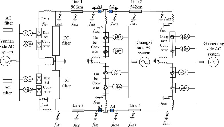
FIGURE 1. Topology diagram of the Kunliulong hybrid multiterminal UHVDC system.
Analysis of Boundary Frequency Characteristics of the Hybrid Multiterminal UHVDC System
The boundary of the conventional DC transmission system and flexible DC transmission system is symmetrical structure. The boundary of the rectifier side and the boundary of the inverter side at the end of the line of the Kunliulong hybrid multiterminal UHVDC system are asymmetrical, so the frequency characteristics of the boundary of the rectifier side and the frequency characteristics of the boundary of the inverter side at the end of the line need to be analyzed separately.
Frequency Characteristics of the Boundary of the Rectifier Side
The rectifier-side line boundary of the Kunliulong hybrid multiterminal UHVDC system comprises both the DC filter and smoothing reactor, and the rectifier-side line boundary of this system is shown in Figure 2 (Chen et al., 2013; Yang et al., 2018; Yang et al., 2019; Yang et al., 2021b).
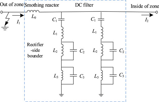
FIGURE 2. Rectifier-side boundary elements.
The rectifier-side line transfer function of the Kunliulong hybrid multiterminal UHVDC system is defined as
The
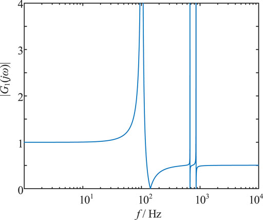
FIGURE 3. Frequency characteristics of transfer function of the rectifier side of the boundary.
As can be seen from Figure 3, when
Inverter-Side Boundary Frequency Characteristics at the End of the Line
The Kunliulong UHV multi-end hybrid DC transmission system is equipped with a smoothing reactor at the end of the transmission line, and there is ground capacitance to the ground, so it is proposed to use a section of overhead line ground capacitance and smoothing reactor at the end of the line to form the inverter side boundary at the end of the line, and the boundary components are shown in Figure 4.
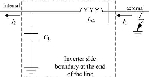
FIGURE 4. Inverter-side boundary at the end of the line.
The transfer function of the inverter side boundary at the end of the line is defined as
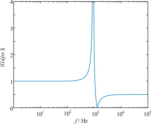
FIGURE 5. Amplitude–frequency characteristics of the inverter-side boundary transfer function at the end of the line.
From Figure 5, the transitory current transfer function
Principle of the CEEMDAN–Teager Energy Operator Algorithm
Basic Principle of the CEEMDAN Algorithm
The CEEMDAN algorithm is improved on the basis of EEMD, which effectively solves the modal mixing phenomenon of EMD and also avoids the problem of unequal number of IMFs after each EMD decomposition in EEMD and CEEMD so that the reconstructed signal is almost identical to the original signal. The algorithm, compared with wavelet decomposition, does not require the selection of basic functions and can achieve complete decomposition of the signal, which is suitable for the processing of nonlinear and nonstationary signals. The specific steps of the algorithm are as follows (Colominas et al., 2013; Wu et al., 2021; Zhang et al., 2021).
(1)
(2) The first-order residuals of CEEMDAN are calculated:
(3) After adding adaptive white noise
(4) Steps (2) and (3) are repeated to obtain the kth residual signal
(5) Step (4) is repeated until the end of the residual signal
The CEEMDAN algorithm finally decomposes the k IMF components with a final residual of
The original signal
From Eq. 9, the CEEMDAN algorithm decomposes the original signal into a series of IMF components with instantaneous frequencies ranging from high to low and one residual to achieve complete decomposition of the signal by adding zero-mean white noise.
Teager Energy Operator
The Teager energy operator is a nonlinear difference operator, and compared with the traditional energy operator, instantaneous energy of the Teager energy operator is related to both amplitude and frequency, with obvious local characteristics, which can quickly perform DC line fault analysis.
The Teager energy operator for the nonlinear signal
where
When the signal is discrete, the Teager energy operator is defined as
The relationship between
where T is the sampling period.
Extraction of High-Frequency Transient Energy of Fault Current Based on the CEEMDAN–Teager Energy Operator
The CEEMDAN algorithm can achieve complete decomposition of the fault current signal, and the IMF components are arranged in the order from highest to lowest frequency band, that is, 2 has the highest frequency band. When the frequency of
Therefore, the DC transmission line protection can be constructed based on the energy magnitude of the high-frequency
The steps to extract the high-frequency transient energy of the fault transient current based on the CEEMDAN-Teager energy operator are as follows:
(1) The fault current signal is obtained and decoupled using phase mode transformation, and the fault current line mode component is obtained.
(2) The mode components of the fault current line obtained in step (1) are decomposed using CEEMDAN to obtain the kth IMF components.
(3) The instantaneous energy of the high-frequency
(4) The rectified value and maximum value of the instantaneous energy of the high-frequency
Hybrid Multiterminal UHVDC Line Protection Scheme
Protection Triggering Criterion
When the DC line fault occurs, the voltage amplitude of the line on both sides of the T-zone changes (Li et al., 2021), the amplitude of the transient voltage can be used as the triggering criterion; in order to improve the protection sensitivity, the side of line with large voltage fluctuation on both sides of the T-zone is selected as the triggering criterion; the triggering criterion is as follows:
where
Protection Direction Criterion
When a fault occurs in the DC line, it is necessary to judge the direction of the fault, and the DC current has definite size and direction (Liu et al., 2020; Muniappan, 2021). For the Kunliulong hybrid multiterminal UHVDC system, under working condition, DC current always flows from Kunbei converter station to Liubei converter station and Longmen converter station, and the specified current reference direction is the bus pointing to the line, as shown in Figure 1.
When the fault occurs on the left side of the T area, the Kunbei-side LCC converter station, the Liubei-side converter station MMC1, and the Longmen-side converter station MMC2 all inject short-circuit current into the short-circuit point; at this time, for protection A1, fault current direction is positive, and protection A1 detects the current increase; for protection A2, the fault current is opposite to the reference direction, so the fault current direction detected by protection A2 is negative, and the current detected by protection A2 becomes smaller; Similarly, when the fault occurs in the right side of the T-zone, protection A1 detects a decrease in current and protection A2 detects an increase in current; when the fault occurs in the T-zone, both protection A1 and protection A2 detect a decrease in current. When the fault occurs in the T-zone, both protection A1 and protection A2 detect a decrease in current.
Analysis of the fault occurred at simulation
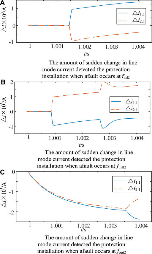
FIGURE 6. Mode component mutation of the fault current line.
As can be seen in Figure 6, when the left side of the T-zone is fault, protection A1 detects the mode component mutation
where
K2 denotes the integral over the time window of the change in the mode component of the current line at the first end of line 2 calculated by protection A2. The calculation formula of k1 and k2 is as follows:
where “x” is taken as 1 or 2,
In- and Out-of-Zone Fault Criterion
After achieving fault direction discrimination, it is also necessary to determine whether the fault occurs in the protection range. When the fault is located in the left side of the T-zone, protection A1 is required to determine the location of the fault; if the fault is located in line 1, protection A1 acts. If the fault is located outside the rectifier side area, protection A1 does not act; when discriminating the fault located in the right side of the T-zone, protection A2 is required to determine the location of the fault, when the fault is located in line 2, protection A2 acts; when the fault is located outside the inverter side area at the end of the line, protection A2 does not act; when the fault is located in the T-zone, this type of fault belongs to the line outside the fault area; hence, protection A1 and protection A2 do not act.
In- and Out-of-Zone Fault Criterion for the Left Side of the T-Zone
Section 2.1 analysis results show that the rectifier side boundary has strong attenuation characteristics for the high-frequency component of the fault current. When the fault is located in the left side of the T-zone, the rectifier-side boundary is used to discern the fault location for the attenuation characteristics of the high-frequency component of the fault transient current. When the fault is located in line 1, the high-frequency signal of the fault current only needs to go through the line attenuation, so the high-frequency component transient energy of the fault current signal is larger; when the fault is located outside the rectifier-side zone, the high-frequency signal of the fault current needs to go through the double attenuation of the rectifier-side boundary and line 1, and the high-frequency component transient energy of the fault current signal is smaller. In order to improve the sensitivity of the protection, the maximum value of the high-frequency component transient energy of the fault current signal is extracted to construct the protection criterion, so the construction of the left side of the T-zone inside and outside the zone fault criterion is as follows:
where
where
Internal and External Faults in the Right-Hand Area of the T-Zone
Section 2.2 analysis results show that the inverter side boundary at the end of the line also has a strong attenuation effect on the high-frequency signal of the fault current. Similarly, the attenuation characteristics of the high-frequency component of the fault current from the inverter side boundary at the end of the line are used to discriminate between internal and external faults in the right-hand side of the T-zone. Fault judgment inside and outside the right side of the T-zone is as follows:
where
where
Criterion of Fault Pole Selection
When judging the fault within the left side of the T-zone or within the right side of the T-zone, in order to make the protection act accurately on the fault pole and ensure normal operation of the non-fault pole, the fault pole discrimination is required, and the fault pole criterion is defined as follows:
P is the pole selection factor, and the calculation formula is as follows:
where
Protection Flow
The protection device starts when the start-up criterion of any of the protection installations on both sides of the T-zone is satisfied. The current data of the 2-ms time window of the line on both sides of the T-zone are taken and decoupled after phase mode transformation and then polarity of the mode component change of the fault current line is calculated, and fault direction discrimination is carried out. When discriminated as the left side of the T-zone fault, protection A1 calculates the maximum value of the instantaneous energy of the high-frequency component of the current line mode at the end of the fault line 1 and judges the fault inside and outside the left side of the T-zone; when discriminated as the right side of the T-zone fault, protection A2 calculates the maximum value of the instantaneous energy of the high-frequency component of the fault current line mode at the first end of the line 2 and discriminates the fault inside and outside the right side of the T-zone; when discerning a fault within the T-zone, A1 and A2 judge the fault to be outside the line zone, where protection A1 and protection A2 are not operating. The current data of fault line 4 ms for fault pole judgment are calculated, the final fault pole protection device action. The protection flow is shown in Figure 7.
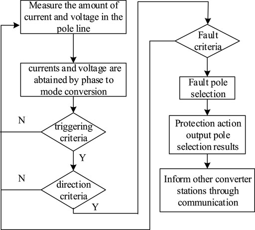
FIGURE 7. Protection flow chart.
Simulation Verification
On the PSCAD/EMTDC simulation platform, the Kunliulong hybrid multiterminal UHVDC system model shown in Figure 1 is built. The Kun-North side adopts the traditional grid phase–shifting type converter with constant DC current and minimum trigger angle control; the Liu-North converter station adopts a hybrid full-bridge and half-bridge modular multiterminal flat converter with constant active power and reactive power control. Longmen converter station uses a full-bridge and half-bridge hybrid modular multiterminal flat converter. Control mode uses fixed DC voltage and reactive power control. Line 1 and line 2 are overhead lines, line model using Frequency Dependent (Phase) Model Options model, the length of 908 km and 542 km, respectively. System parameters are shown in Table 1. The main parameters of the system are shown in Table 1.

TABLE 1. Main parameters of the simulation system.
In Figure 1,
According to the protection scheme proposed in Principle of the CEEMDAN–Teager Energy Operator Algorithm, the protection algorithm is written in MATLAB, and the simulation data are imported. This study uses the CEEMDAN algorithm to decompose the first IMF component after the fault transient current; it can be achieved when the center frequency is greater than the boundary decay frequency. Considering the CEEMDAN decomposition principle and Shannon’s theorem to engineering practical impact factors, this study involves simulation sampling frequency using 20 kHz, and the data window length is 4 ms (Shen et al., 2021a; Shen et al., 2021b; Shen and Raksincharoensak, 2021a; Shen and Raksincharoensak, 2021b).
The intra-area fault in the left area of the T-zone is taken as an example. If the center point of line 1 is metallic ground, the moment of fault occurrence is 1 s, the fault duration is 0.1 s, and the amount of line voltage change on both sides of the T-zone is shown in Figure 8.
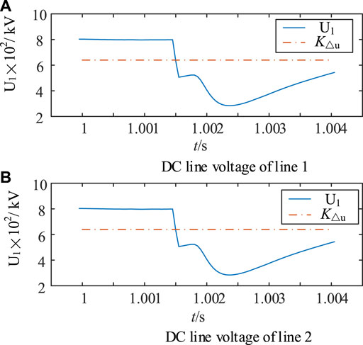
FIGURE 8. Voltage of DC lines.
It can be seen from Figure 8 that when the midpoint of line 1 metal ground fault and line 1 and line 2 voltage are down to reach the protection of the start value, the protection process is started. According to the protection process to discriminate the fault direction, line 1 and line 2 current line mode change amount is as shown in Figure 9.
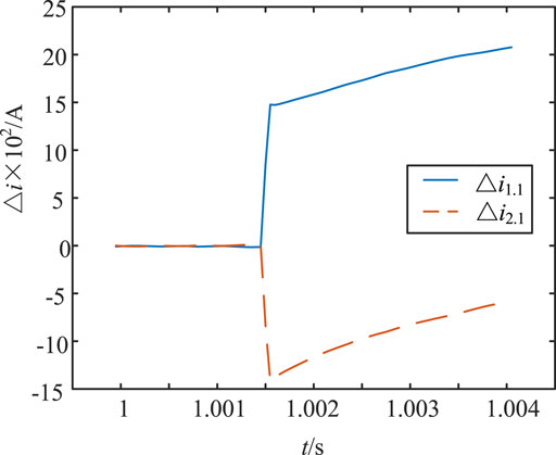
FIGURE 9. Sudden change amount of the fault current line mode component.
From Figure 9, it can be seen that when the line 1 of the midpoint of a metallic ground fault protection A1 detecting the mode change amount of the current line at the end of line 1 is positive, protection A2 detecting the mode change amount of the current line at the first end of line 2 is negative. According to Eq. 18, it can be determined that the fault occurred on the left side of the T-zone. According to the protection process, the location can be determined. The mode components of the fault transient current line for CEEMDAN decomposition can be obtained for each order IMF component as shown in Figure 10, and the FFT transform of each order IMF component to find its spectrum, as shown in Figure 11.
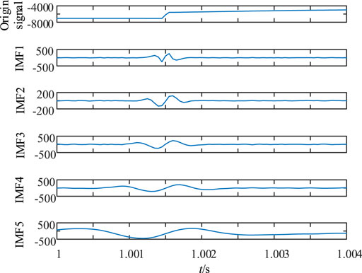
FIGURE 10. Decomposition results of CEEMDAN.
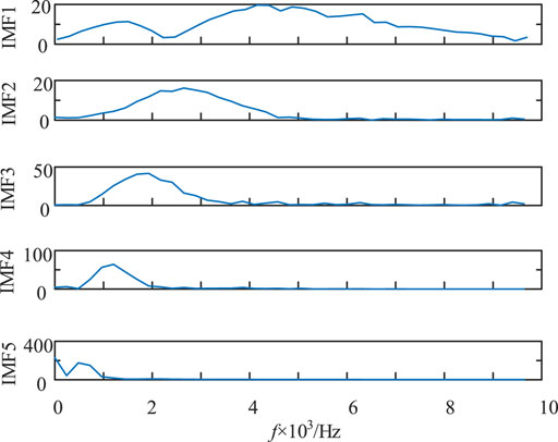
FIGURE 11. Frequency spectrum of CEEMDAN modal components.
As seen in Figures 10, 11, the mode signal of the fault transient current line is decomposed by CEEMDAN to obtain IMF1∼IMF5, which is FFT-transformed to find the center frequency of IMF1 as 5.3 kHz, and the center frequency is greater than the boundary decay frequency, and the energy spectrum of IMF1 is calculated by using the Teager energy operator, and the energy spectrum of IMF1 is shown in Figure 12.
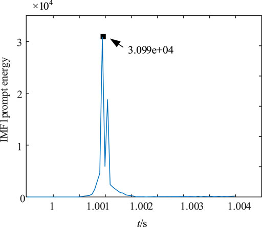
FIGURE 12. IMF1 component energy spectrum.
From Figure 12, we can see that the maximum value of the instantaneous amplitude of the IMF1 component is
In order to verify the impact of different fault locations and different transition resistances on the protection, (shen et al., 2020a; shen et al., 2020b) this study selected
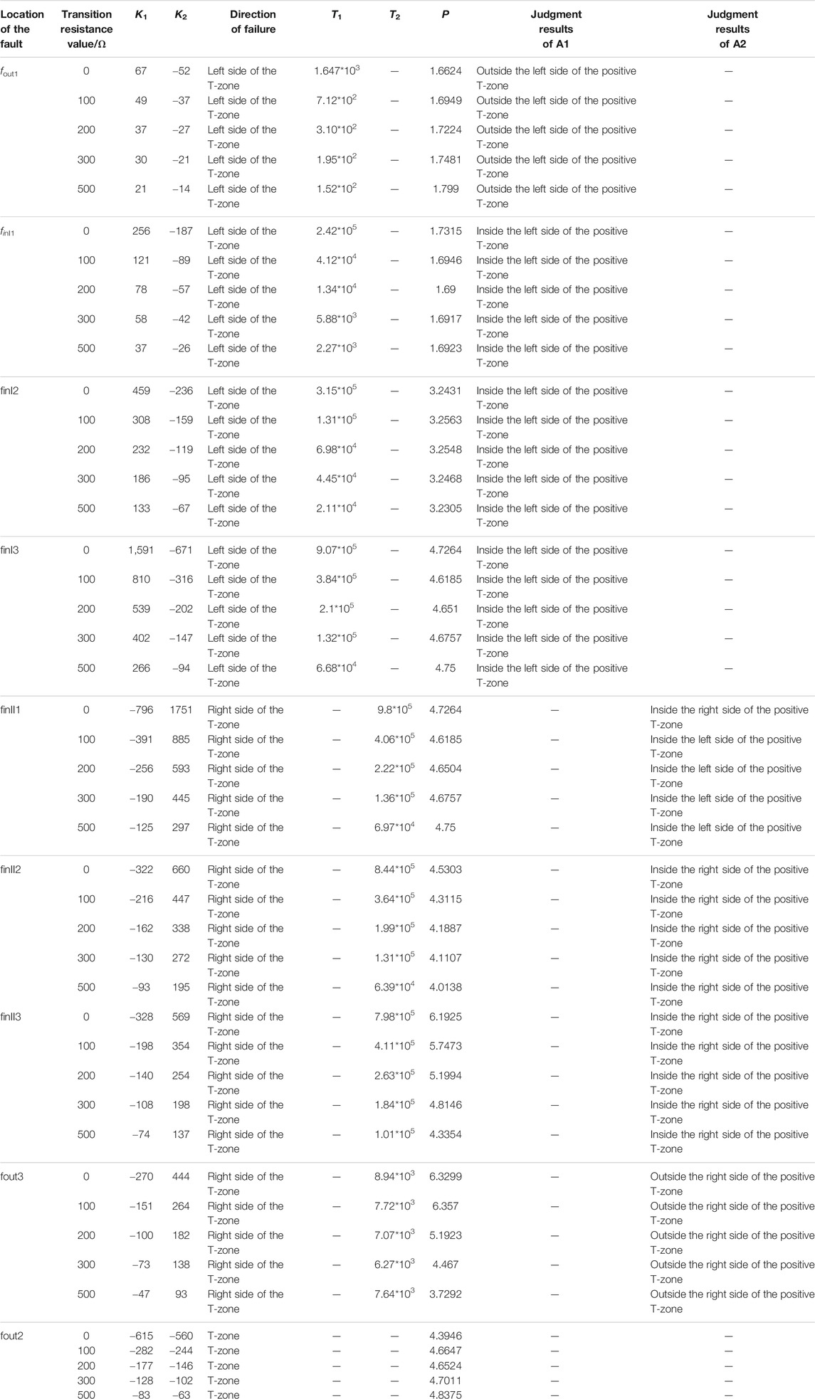
TABLE 2. Simulation of the positive fault.
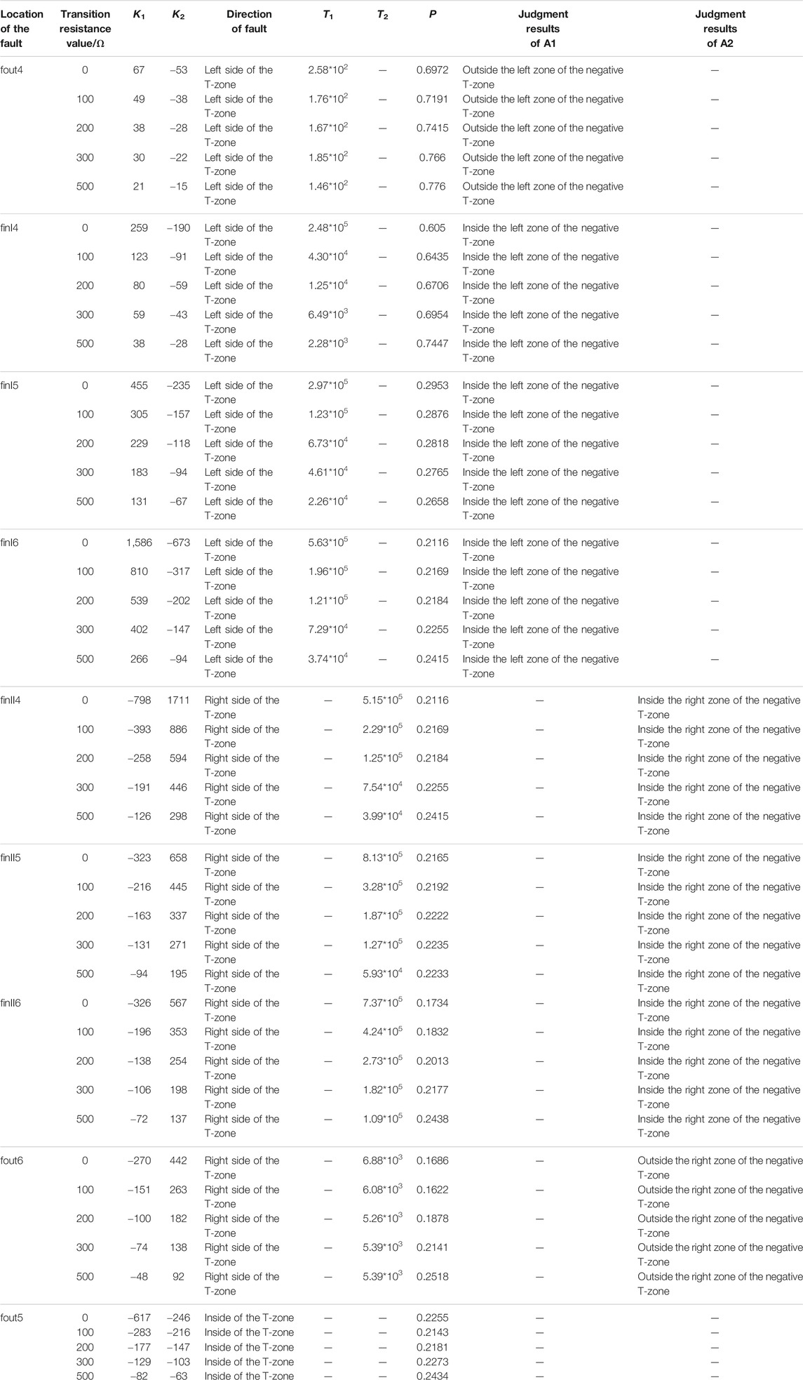
TABLE 3. Simulation of the negative fault.
From Tables 2, 3, it can be seen that when the fault occurs at
Summary
In this study, a protection scheme for hybrid multiterminal UHVDC lines based on the CEEMDAN–Teager energy operator is proposed, which uses the protection principle to discriminate the fault direction by the polarity of the sudden change in the line mode component of the fault current when a fault occurs on both sides of the T-zone, and then according to the rectifier-side boundary or line end inverter-side boundary on the fault transient current high-frequency signal attenuation characteristics, to determine the left side of the T area inside and outside the fault area or the right side of the T area inside and outside the fault area. The protection principle has the following advantages:
1) When the fault occurs, because the normal operation of DC current has a clear direction and size, the current on both sides of the line will be obvious to sudden changes, and one can use the polarity of the current line mode component of the sudden change in the construction of the direction of the criterion.
2) The adaptive nature of CEEMDAN decomposition and accurate identification ability of the Teager energy operator are used to determine the faults inside and outside the left side of the T-zone and the right side of the T-zone, respectively.
3) The method in this study does not require high sampling frequency and has strong resistance to transition resistance, and the time window is 4 ms, which can quickly and accurately determine the faults inside and outside the zone.
Data Availability Statement
The original contributions presented in the study are included in the article/Supplementary Material; further inquiries can be directed to the corresponding author.
Author Contributions
CX was responsible for providing ideas and methods and providing an experimental platform. YC was responsible for deriving formulas, reviewing, and verifying. LW was responsible for model building, simulation, data analysis, and manuscript writing. GB, SC, and JG wrote sections of the manuscript. All authors participated in the reading and approved the submitted version.
Funding
The research is funded by the National Natural Science Foundation of China (52067009).
Conflict of Interest
Author CX is studying for his doctor’s degree in Tianjin University and employed by the Electric Power Research Institute, Southern Power Grid Yunnan Electric Power Co., Ltd. Author YC works at the Key Laboratory of Smart Grid of Education Ministry of Tianjin University.
The remaining authors declare that the research was conducted in the absence of any commercial or financial relationships that could be construed as a potential conflict of interest.
Publisher’s Note
All claims expressed in this article are solely those of the authors and do not necessarily represent those of their affiliated organizations, or those of the publisher, the editors, and the reviewers. Any product that may be evaluated in this article, or claim that may be made by its manufacturer, is not guaranteed or endorsed by the publisher.
References
Boussaadia, F . (2019), Reliability Analysis of Transmission Lines protection Systems of the SONELGAZ Power System[C]//Algerian Large Electrical Network Conference. 0. doi:10.1109/CAGRE.2019.8713173
Chen, S., Shu, H., Xie, J., Cai, Z., and Zhang, W. (2013). Frequency Characteristics of UHVDC Transmission Line and its Boundary[J]. Electric Power Automation Equipment 33 (11), 134–139+153. doi:10.3969/j.issn.1006-6047.2013.11.024
Chen, Z., Zhou, Z., and Wang, X. (2019). Research on protection Scheme of Hybrid Multi-Terminal DC Transmission Lines[J]. Power Syst. Tech. 43 (07), 2617–2622. doi:10.13335/j.1000-3673.pst.2018.2400
Colominas, M. A., Schlotthauer, G., Torres, M. E., and Flandrin, P. (2013). Noise-Assisted Emd Methods in Action[J]. Adv. Adaptive Data Anal. 4 (04). doi:10.1142/S1793536912500252
Gao, S., Gao, Yue., and Song, G. (2020). A protection Method Based on Instaneous Engery of Teager Operator for Modular Multilevel Converter Multiterminal Flexible Direct Current Grid[J]. J. Xi’an Jiaotong Univ. 54 (09), 40–48. doi:10.7652/xjtuxb202009004
Gao, S., Zeng, Z., and Song, G. (2021). A Differential protection Scheme for Hybrid Three-Terminal DC System[J]. J. Xi’an Jiaotong Univ. 55 (01), 17–26. doi:10.7652/xjtuxb202101003
He, J., Chen, K., Li, M., Luo, Y., Liang, C., and Xu, Y. (2020). Review of protection and Fault Handling for a Flexible DC Grid. Prot. Control. Mod. Power Syst. 5, 15. doi:10.1186/s41601-020-00157-9
Karimian, A., and Hosseinian, S. H. (2020). Online Tracking of Voltage Flicker for Inverter‐based Distributed Generation Using Teager Energy Operator [J]. Int. Trans. Electr. Energ. Syst. 30 (4). doi:10.1002/2050-7038.12292
Le, S., Wu, Y., Guo, Y., and Vecchio, C. D. (2021). Game Theoretic Approach for a Service Function Chain Routing in NFV with Coupled Constraints. IEEE Trans. Circuits Syst. 68, 3557–3561. Published online. doi:10.1109/TCSII.2021.3070025
Li, B., He, J., Feng, Y., Li, Y., Li, G., and Qiu, H. (2016). Key Techniques for Protection of Multi-Terminal Flexible DC Grid[J]. Automation Electric Power Syst. 40 (21), 2–12. doi:10.7500/AEPS20160601011
Li, H., Zhang, K., and Wang, G., Fault Area Discrimination Method for Parallel Multi-Terminal Hybrid HVDC DC Line[J]. Automation Electric Power Syst., 2019, 43(04): 119–125.±179+126-128. doi:10.7500/AEPS20180615004
Li, J., and Li, Q. (2015). Medium Term Electricity Load Forecasting Based on CEEMDAN-Permutation[J]. Electric Machines and Control 19 (008), 70–80. doi:10.15938/j.emc.2015.08.011
Li, S., Chen, W., Yin, X., Chen, D., and Teng, Y. (2019). A Novel Integrated Protection for VSC-HVDC Transmission Line Based on Current Limiting Reactor Power[J]. IEEE Trans. Power Deliv. 35 (1), 226–233. doi:10.1109/tpwrd.2019.2945412
Li, Z., Jiang, W., Abu-Siada, A., Li, Z., Xu, Y., and Liu, S. (2021). Research on a Composite Voltage and Current Measurement Device for HVDC Networks. IEEE Trans. Ind. Electron. 68 (9), 8930–8941. doi:10.1109/tie.2020.3013772
Lin, X., Qi, L., and Fan, L. (2020). Blocking Pilot protection Based on Ratio of Superimposed Energy for VSC-MTDC Grid[J]. Automation Electric Power Syst. 40 (04), 2–8+16. doi:10.16081/j.epae.202004024
Liu, Y., Yang, N., Dong, B., Wu, L., Yan, J., Shen, X., et al. (2020). Multi-Lateral Participants Decision-Making: A Distribution System Planning Approach with Incomplete Information Game. IEEE Access 8, 88933–88950. doi:10.1109/access.2020.2991181
Muniappan, M. (2021). A Comprehensive Review of DC Fault protection Methods in HVDC Transmission Systems. Prot. Control. Mod. Power Syst. 6 (1), 1–20. doi:10.1186/s41601-020-00173-9
Ren, Z., Cheng, J., and Xing, Q. (2017). A Harmonic Detection Method Based on CEEMDAN and Teager Energy Operator Algorithm[J]. Power Syst. Prot. Control. (9), 56–62. doi:10.7667/PSPC160634
Shen, X., Ouyang, T., Khajorntraidet, C., Li, Y., Li, S., and Zhuang, J. (2021a). Mixture Density Networks-Based Knock Simulator. Ieee/asme Trans. Mechatron., 1. doi:10.1109/TMECH.2021.3059775
Shen, X., Ouyang, T., Yang, N., and Zhuang, J. (2021b). Sample-based Neural Approximation Approach for Probabilistic Constrained Programs. IEEE Trans. Neural Netw. Learn. Syst., 1–8. doi:10.1109/TNNLS.2021.3102323
Shen, X., and Raksincharoensak, P. (2021a). Pedestrian-aware Statistical Risk Assessment. IEEE Trans. Intell. Transport. Syst., 1–9. doi:10.1109/TITS.2021.3074522
Shen, X., and Raksincharoensak, P. (2021b). Statistical Models of Near-Accident Event and Pedestrian Behavior at Non-signalized Intersections. J. Appl. Stat., 1–21. doi:10.1080/02664763.2021.1962263
Shen, X., Zhang, X., Ouyang, T., Li, Y., and Raksincharoensak, P. (2020a). Cooperative Comfortable-Driving at Signalized Intersections for Connected and Automated Vehicles. IEEE Robot. Autom. Lett. 5 (4), 6247–6254. doi:10.1109/LRA.2020.3014010
Shen, X., Zhang, Y., Sata, K., and Shen, T. (2020b). Gaussian Mixture Model Clustering-Based Knock Threshold Learning in Automotive Engines. Ieee/asme Trans. Mechatron. 25 (6), 2981–2991. doi:10.1109/TMECH.2020.3000732
Shen, X., Zhang, Y., Shen, T., and Khajorntraidet, C. (2017). Spark advance Self-Optimization with Knock Probability Threshold for Lean-Burn Operation Mode of SI Engine. Energy 122 (3), 1–10. doi:10.1016/j.energy.2017.01.065
Song, G., Hou, J., Guo, B., Chen, Z., et al. (2020). Pilot protection of Hybrid MMC DC Gridbased on Active Detection. J. Prot. Control. Mod. Power Syst. V5 (1), 82–96. doi:10.1186/s41601-020-0152-2
Tian, P., Wu, Q., and Huang, j. (2021). Research on protection Strategy of a Hybrid Multi-Terminal DC System Based on LCC and FHMMC[J]. Power Syst. Prot. Control. 49 (01), 170–177. doi:10.19783/j.cnki.pspc.200211
Toyoda, M., and Wu, Y. (2021). Mayer-type Optimal Control of Probabilistic Boolean Control Network with Uncertain Selection Probabilities. IEEE Trans. Cybern. 51, 3079–3092. doi:10.1109/tcyb.2019.2954849
Vanra, J., Dhami, S. S., and Pabla, B. S. (2017). Non-Contact Incipient Fault Diagnosis Method of Fixed-Axis Gearbox Based on CEEMDAN. R. Soc. Open Sci. 4 (8), 170616. doi:10.1098/rsos.170616
Wang, L., and Shao, Y. (2020). Fault Feature Extraction of Rotating Machinery Using a Reweighted Complete Ensemble Empirical Mode Decomposition with Adaptive Noise and Demodulation Analysis[J]. Mech. Syst. signal Process. 138 (Apr), 1065451–1106545.20. doi:10.1016/j.ymssp.2019.106545
Wang, Y., Fan, X., and Zhang, B. (2019). The Analytical Analysis and Protection Setting of Traveling Wave Protection in VSC-HVDC Grid[J]. Proc. CSEE 39 (11), 3201–3212. doi:10.13334/j.0258-8013.pcsee.181633
Wu, Y., Guo, Y., and Toyoda, M. (2021). Policy Iteration Approach to the Infinite Horizon Average Optimal Control of Probabilistic Boolean Networks. IEEE Trans. Neural Netw. Learn. Syst. 32 (6), 2910–2924. doi:10.1109/TNNLS.2020.3008960
Yang, N., Ye, D., Zhou, Z., Cui, J., Chen, D., and Wang, X. (2018). Research on Modelling and Solution of Stochastic SCUC under AC Power Flow Constraints[J]. IET Generation, Transm. Distribution 12 (15), 3618–3625. doi:10.1049/iet-gtd.2017.1845
Yang, N., Huang, Y., Hou, D., Liu, S., Ye, D., Dong, B., et al. (2019). Adaptive Nonparametric Kernel Density Estimation Approach for Joint Probability Density Function Modeling of Multiple Wind Farms. Energies 12, 1356. doi:10.3390/en12071356
Yang, N., Liu, S., Deng, Y., and Xing, C. (2021b). An Improved Robust SCUC Approach Considering Multiple Uncertainty and Correlation. IEEJ Trans. Elec Electron. Eng. 16, 21–34. doi:10.1002/tee.23265
Yang, N., Qin, T., Wu, L., Huang, Y., Huang, Y., Xing, C., et al. (2022). A Multi-Agent Game Based Joint Planning Approach for Electricity-Gas Integrated Energy Systems Considering Wind Power Uncertainty. Electric Power Syst. Res. 204, 107673. ISSN 0378-7796. doi:10.1016/j.epsr.2021.107673
Yang, N., Yang, C., Wu, L., Shen, X., Jia, J., Li, Z., et al. (2021c). Intelligent Data-Driven Decision-Making Method for Dynamic Multi-Sequence: An E-Seq2Seq Based SCUC Expert System. IEEE Trans. Ind. Inf., 1. doi:10.1109/TII.2021.3107406
Yang, N., Yang, C., Xing, C., Ye, D., Jia, J., Chen, D., et al. (2021a). Deep Learning‐based SCUC Decision‐making: An Intelligent Data‐driven Approach with Self‐learning Capabilities. IET Gener. Transm. Distrib., 1–12. doi:10.1049/gtd2.12315
Zhang, Lei., Xie, Y., Ye, J., Xue, T., Cheng, J., Li, Z., et al. (2021). Intelligent Frequency Control Strategy Based on Reinforcement Learning of Multi-Objective Collaborative Reward Function[J]. Front. Energ. Res. Early Access. doi:10.3389/fenrg.2021.760525(SCI)
Zheng, X., Wang, S., Li, N., Xiao, H., and Jiang, W. (2016). A LCC and MMC Series Hybrid HVDC Topology Suitable for Bulk Power Overhead Line Transmission[J]. Power Syst. Tech. 40 (01), 55–63. doi:10.13335/j.1000-3673.pst.2016.01.008
Keywords: hybrid multiterminal UHVDC system, line protection, CEEMDAN, Teager energy operator, PSCAD/EMTDC simulation
Citation: Xing C, Wang L, Bi G, Chen S, Gao J and Che Y (2022) A Study of Protection Method for Hybrid Multiterminal UHVDC Lines Based on CEEMDAN–Teager Energy Operator. Front. Energy Res. 10:840967. doi: 10.3389/fenrg.2022.840967
Received: 21 December 2021; Accepted: 24 January 2022;
Published: 21 February 2022.
Edited by:
Xun Shen, Tokyo Institute of Technology, JapanReviewed by:
Hardeep Singh, Sophia University, JapanSandeep Kumar, Lovely Professional University, India
Copyright © 2022 Xing, Wang, Bi, Chen, Gao and Che. This is an open-access article distributed under the terms of the Creative Commons Attribution License (CC BY). The use, distribution or reproduction in other forums is permitted, provided the original author(s) and the copyright owner(s) are credited and that the original publication in this journal is cited, in accordance with accepted academic practice. No use, distribution or reproduction is permitted which does not comply with these terms.
*Correspondence: Yanbo Che, bGFiNTM4QDE2My5jb20=