 Xuanjun Zong
 Yue Yuan1
- 1College of Energy and Electrical Engineering, Hohai University, Nanjing, China
- 2School of Electric Power Engineering, Nanjing Institute of Technology, Nanjing, China
In this paper, aiming to achieve the target of carbon emission orientation, a multi-objective optimization model of the multi-energy flow coupling system is proposed, in which all the environmental protection, system economy, and energy efficiency are comprehensively considered as the addressed objectives. To solve the developed model, by combining the analytic hierarchy process (AHP) and the improved entropy weight method, a so-called AHP-improved entropy weight method is proposed and utilized for weighting the considered objectives, and the model is transformed into a single objective optimization problem, namely, the collaborative optimization model. Then, to expedite the process, a simplified primal dual interior point method is proposed to solve the model. Finally, the results of a case study indicate that the proposed multi-objective collaborative optimization can obtain the optimal solution of the system. In addition, the convergence and global optimization ability of the simplified primal dual interior point method show better characteristics when solving the proposed model.
1 Introduction
Energy is the basis and important guarantee for human survival. There are many problems in traditional energy systems, such as independent energy supply, low cascade utilization level, energy waste, and environmental pollution (Zhou et al., 2013; Fan et al., 2021; Hu et al., 2022). The multi-energy flow coupling system (MEFCS) is an energy system form that integrates public cold, heat, electricity, and gas. Its purpose is to integrate multiple energy sources, such as electric energy, natural gas, and thermal energy in a certain area, so as to realize collaborative optimal operation, collaborative management, and complementary mutual assistance among various forms of energy subsystems (Zhao et al., 2018; Klyapovskiy et al., 2019). In addition, under the background of “double carbon”, the transformation of clean and low-carbon energy is an inevitable trend of global energy development.
Traditional energy systems are planned and operated independently, and only a single situation needs to be considered in their optimal scheduling. However, for a multi-energy flow coupling system, the correlation among energy subsystems should be considered in planning and operation (Sirvent et al., 2017). In Liu et al. (2019), considering the multi-timescale characteristics, an electrical and thermal energy sharing model of interconnected microgrids with combined heating and power (CHP) and photovoltaic systems was built, in which CHP could operate in a hybrid mode by selecting the operating point flexibly. In Wang et al. (2019), a multi-objective bi-level optimization model considering the total cost and carbon dioxide emission was built, while the energy efficiency of multi-energy flow coupling system was ignored. In Barati et al. (2015) and Clegg and Mancarella (2016), under the condition of meeting the basic needs of power, gas, and heat loads, the coordinated planning of multi-energy flow coupling system was considered, in order to reduce the construction cost of transmission lines, gas pipelines, and power plants as much as possible. In Koltsaklis and Knápek (2021), the authors presented an optimization framework for the optimal scheduling of a multi-energy microgrid, where a number of aggregated end-users were considered. In Nicolosi et al. (2021), a novel mixed integer linear programming optimization algorithm has been developed to compute the optimal management of a micro-energy grid, where the total cost, the NOx, and the CO2 emissions of the system were taken into consideration. To meet the safety constraints, in Wang D. et al. (2018), an optimal coordination control strategy (OCCS) for a hybrid energy storage system was developed considering the state-space equation to describe the OCCS, the constraints of the OCCS, and the objective function to express the optimal coordination control performance. In Sun et al. (2020), the authors considered the day ahead optimal scheduling problem of electricity gas interconnected systems, where the two-way energy flow was taken as a non-convex nonlinear mixed integer linear programming problem, and a second-order cone programming (SOCP) method has been proposed. In Luo et al. (2018) and Zhang et al. (2021), the uncertainty caused by renewable energy and multi-energy load was considered, and the robust optimization and stochastic optimization methods were adopted to deal with it respectively, so as to ensure that the system can still maintain stable operation under the worst conditions. In Ghosh and Kamalasadan (2017), a grid-connected two mass DFIG and a grid-supportive single mass squirrel cage induction generator-based flywheel energy storage system model have been considered for controller design and proof-of-concept exploration. In Wang L. et al. (2021), the flexible resources (FRs) on both the energy supply and load sides were introduced into the optimal dispatch of the integrated electricity-heat energy system (IEHES) and further modeled to alleviate the renewable fluctuations, and the solution for FRs participating in IEHES dispatch was given, with goals of maximizing the renewable penetration ratio and lowering operation costs. It can be seen that most of the existing results consider optimization of the economic objectives of the multi-energy flow coupling system, where the index is relatively single, and less consideration is paid on the carbon emission level in the operation of the system. At the same time, the operation strategy is the lack of comprehensive comparison and verification.
In solving the MEFCS collaborative optimization model, when considering multiple optimization objectives including carbon emission, investment and operation cost, and energy utilization, the traditional single objective optimization algorithm may be difficult to ensure that the solution result is the optimal solution of the original problem. In Wang W. et al. (2021), the load characteristics and various constraints of the integrated community energy system were considered, and the operating model with the goal of minimizing operating costs was optimized. In Ma et al. (2018), the energy consumption cost and environmental cost of the multi-energy flow coupling system were considered comprehensively, the optimal scheduling model of multi-energy flow coupling system was proposed, and the optimal scheduling model was transformed into a mixed integer linear programming problem. In Xiao et al. (2018), the method of the probability scenario had been used to model the uncertainties of the distributed renewable energies (DREs) and loads, which could better characterize the impact of uncertainty on the planning and design of the MEFCS. In Yang et al. (2018), a two-stage robust generation scheduling model was proposed for the dynamic safety constraints of the natural gas pipeline network and the uncertainty of wind power, and a new solution method was developed to avoid the nonlinearity of gas flow constraints. In Wu et al. (2021), the multi-objective optimization model was transformed into a single objective optimization model through the multi-objective programming hierarchical solution method, and the primal dual interior point method was used to solve the model. Based on the fast particle swarm optimization algorithm, in Qu et al. (2021), a dual-decomposition-based distributed algorithm was designed to address the problem that the data and information of the EHs during the operation were confidential and should be kept by each owner, where the optimal consensus problem was used for the dual problem to update the multipliers, in Li et al. (2020), the proposed MEFCS planning model, formulated as a two-stage MILP problem, was solved by the Benders decomposition (BD) method to determine the optimal capacity of each component in MEFCS planning.
To be pointed out that, the research on the optimization of multi-energy flow coupling system at home and abroad mainly focuses on the simplification of the optimization model. However, on the one hand, it will lead to the reduction of solution accuracy, at the same time, because the models are more and more complex, which are difficult to be simplified. Therefore, the heuristic algorithm has become an important way to deal with optimization problems. However, the traditional heuristic algorithm has the problems of poor convergence and easy to fall into local optimization, and how to find a simplified and better algorithm is another motivation of this paper. Based on the above discussions, in this paper, the environmental protection goal is taken as the leading factor, the economic and energy efficiency goals are comprehensively considered, the multi-objective collaborative optimization model is developed for the multi-energy flow coupling system, which can be transformed into a single objective optimization model through the linear combination of the analytic hierarchy process and the improved entropy weight method, and then the model can be solved by using the simplified primal dual interior point method. The results avoid falling into local optimization and accelerate convergence. Case studies verify the effectiveness of the proposed algorithm.
2 Modeling of Multi-Energy Flow Coupling System
A typical multi-energy flow coupling system structure is shown in Figure 1, which is internally connected through the power grid, thermal pipe network, and cooling transmission network. The equipment involved distribution power source includes a wind turbine (WT) and photovoltaic (PV). Cogeneration includes CHP, a gas turbine (GT), a waste heat boiler (WHB), a ground source heat pump (HP), an electric refrigerator (ER), an absorption refrigerator (AR), and other energy conversion equipment, as well as electric energy storage (EES), heat energy storage (HES), and other energy storage equipment.
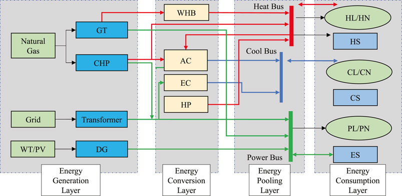
FIGURE 1. Typical structure of the multi-energy flow coupling system.
2.1 Modeling of Distributed Generations
2.1.1 Wind Turbine
where
2.1.2 Photovoltaic
where
2.2 Modeling of Energy Conversion Unit
2.2.1 Cogeneration Unit
The cogeneration unit generates electric energy and heat energy at the same time by consuming natural gas. Its operation mode can be expressed as
where
2.2.2 Gas Turbine and Waste Heat Boiler
The gas turbine generates electric energy by consuming natural gas, and part of the discharged flue gas can be transformed into available calorific value through a waste heat boiler. Their working characteristics can be expressed as
where
2.2.3 Ground Source Heat Pump
The heat pump is a high-efficiency and energy-saving equipment in the multi-energy flow coupling system. It can convert low-grade heat energy into high-grade heat energy by consuming electric energy. Its operation mode is given by
where
2.2.4 Electric Chiller and Absorption Chiller
The electric chiller generates cold power by consuming electric power during operation, and the absorption chiller generates cold power by absorbing thermal power. Its mathematical model is as follows:
where
2.3 Modeling of Energy Storage Equipment
where
3 Modeling of Multi-Objective Collaborative Optimization
In the multi-objective collaborative optimization of MEFCS considering carbon emissions, the optimization objectives considered in this paper include the environmental protection objective, economic objective, and energy efficiency objective.
3.1 Each Optimization Objective Function
3.1.1 Environmental Protection Objective
Aiming at minimizing the
where
3.1.2 Economic Objective
In order to minimize the operation cost of MEFCS in 1 day, the optimization model can be formulated as
where
3.1.3 Energy Efficiency Objective
Primary energy utilization is defined as the ratio of MEFCS load to MEFCS primary energy input in a day. Aiming at the maximum utilization of primary energy, the optimization model can be formulated as
where
3.2 Constraint Condition
3.2.1 Energy Balance Constraints
1) Power balance constraint
2) Heat energy balance constraint
3) Cool energy balance constraint
3.2.2 Upper and Lower Limits of Equipment Output
where
3.2.3 Energy Storage Constraints
where
3.3 Collaborative Optimization Objective
The developed optimization model is a multi-objective optimization problem. First, the optimal solution of each objective is obtained through single objective optimization, and then the optimization results of each objective are standardized, so the multi-objective optimization is transformed into single objective optimization with the help of the linear weighting method. Finally, the single objective optimization algorithm can be solved.
3.3.1 Normalization and Standardization
As the environmental protection goal and economic goal belong to very small goals, that is, the smaller the final result, the better, while the energy efficiency goal belongs to maximum goals, the larger the final result, the better. Therefore, before establishing the collaborative optimization objectives, each single objective should be normalized and standardized, which can be expressed as follows:
where
3.3.2 Index Weighting
Generally, the methods of weighting indicators can be divided into subjective method, objective method, and the combination of subjective and objective methods. The subjective weighting method is simple to operate and does not need the support of original data, but the subjectivity of weighting results is often too large. The objective weighting method can show the relationship between indicators well, but it has high requirements for the original data. Therefore, in this paper, a new combination method based on the analytic hierarchy process (AHP) and the improved entropy weight method is adopted.
The analytic hierarchy process first judges the relative importance of each index through decision-making experts and scores each index with an integer between 1 and 9, and then the judgment matrix is obtained,
where n denotes the number of indicators. A is a positive reciprocal matrix, which satisfies
To be noted that, due to the environmental protection goal is taken as the leading factor in this paper, when forming the judgment matrix, the score of the environmental protection index is relatively high so that the final weight is relatively maximum.
Then check the consistency of the judgment matrix,
where
When the judgment matrix A passes the consistency check, the eigenvector corresponding to its maximum eigenvalue
The entropy weight method reflects the amount of information contained in each index through the entropy value of each index. Generally speaking, the smaller the entropy value, the greater the amount of index information and the greater the weight should be set. Since the standard entropy weight method is mainly applied to multiple schemes, the entropy weight method can be improved by
where
To be noted that, this improvement is mainly to adapt to the optimization model. The objective functions have been processed and converted into the form of membership function. Therefore, in order to adapt to this form, the index value is replaced by membership
According to the calculation results of entropy value of each index, the weight of each index can be obtained by
Therefore, the weight vector is obtained by the improved entropy weight method,
In order to obtain the combined weight of AHP and improved entropy weight method, the coupling vector is taken as follows:
where
Therefore, the weight after coupling is
Normalize it, one has
Then, the combined weight of the AHP improved entropy weight method can be finally expressed as
3.3.3 Collaborative Optimization Objective
After obtaining the index weight, combined with the standardized objective function in the above sections, we can obtain the comprehensive satisfaction goal, that is, the collaborative optimization objective is given as
4 Optimization Algorithm
Based on the above analysis, it can be found that the multi-objective collaborative optimization of the multi-energy flow coupling system considered in this paper is a complex nonlinear programming problem. In order to make the solution speed and convergence meet the requirements of practical problems, the simplified primal dual interior point algorithm is used in this paper. For the sake of brevity, first, the optimization model described above is transformed into the following general form:
where
When dealing with this optimization model with the traditional interior point algorithm, relaxation variables
At the same time, the size of relaxation variables
where
At this point, the inequality constraints contained in the optimization model described in this paper have all been converted into the equality constraints, and the Lagrange function for this optimization problem can be expressed as
where
In this paper, by simplifying the original dual interior point algorithm, the simplified original dual interior point method can be utilized to solve the optimization model, and the simplified process is to rewrite the inequality constraint to
where
It can be found from the traditional interior point algorithm that in the process of dealing with inequality constraints, the upper and lower bounds of inequality constraints need to be relaxed, and then converted into equality constraints, respectively. At the same time, Lagrange operators are also introduced for equality constraints converted from upper-bound inequality constraints and lower-bound inequality constraints, respectively, which introduce more variables in the Lagrange function. This simplification algorithm greatly reduces the relaxation variables and corresponding Lagrange operators introduced in the optimization model, improves the convergence speed of the algorithm while guaranteeing the calculation accuracy, and reduces the amount of programming to a certain extent. The rest of the algorithm is handled similarly to the traditional algorithm, which are not discussed here. For ease of understanding, the multi-objective collaborative optimization calculation flow of the multi-energy flow coupling system based on the simplified primal dual interior point algorithm is shown in Figure 2, where
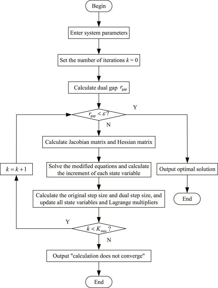
FIGURE 2. Calculation flow of multi-objective collaborative optimization.
Based on the above analysis, the collaborative optimization of MEFCS dominated by the carbon emission targets in this paper can be summarized as the following steps:
Step 1. Enter parameter information of the multi-energy flow coupling system, such as system load, rated capacity of each unit, equipment parameters, and time-of-use electricity price.
Step 2. Establish the steady-state operation model of each equipment, as shown in Eqs 1–7.
Step 3. Establish the objective functions and constraints of the MEFCS, as shown in Eqs 8–15.
Step 4. Weight each objective function using the analytic hierarchy process-improved entropy weight method, as shown in Eqs 18–28.
Step 5. Convert each objective function into a collaborative optimization objective through the membership function and the obtained weight information, as shown in Eqs 16, 17, 29.
Step 6. Solve the MEFCS collaborative optimization model by the primal dual interior point algorithm until the optimal solution is obtained or the algorithm does not converge.
The above steps can be clearly represented by the flowchart shown in Figure 3.
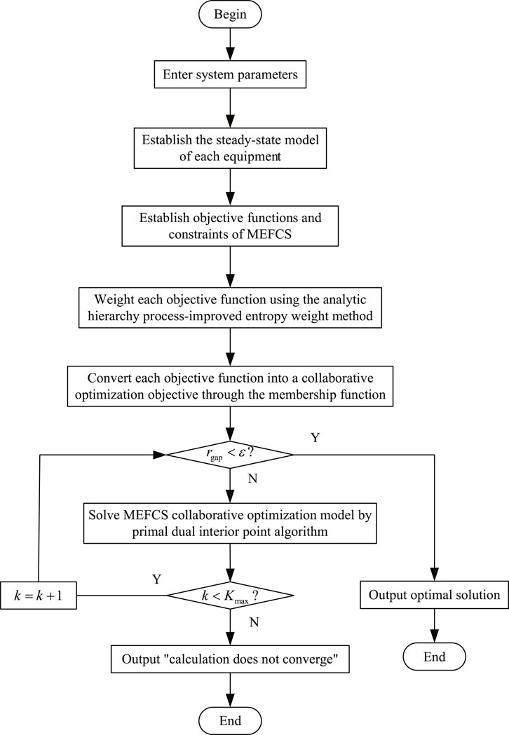
FIGURE 3. Flowchart of the collaborative optimization of MEFCS.
5 Case Study
5.1 Case Description
In this paper, the typical multi-energy flow coupling system shown in Figure 1 is selected as an example. The capacity of each equipment is as follows: one photovoltaic generator unit with a rated output of 700 kW and one wind turbine generator unit with a rated output of 500 kW, one cogeneration unit with a rated output of 3 MW, one gas turbine with a rated output of 2 MW, one waste heat boiler with a rated output of 1 MW, four heat pumps with a rated output of 500 kW, four electric refrigerators and four absorption refrigerators with a rated output of 200 kW, and four batteries and heat storage equipment with a rated capacity of 500 kwh. Other economic and technical parameters of the equipment can be found in Wang Y. et al. (2018) and Huang et al. (2019). The time of use electricity price information of the multi-energy flow coupling system is shown in Figure 4, and the price of natural gas is 2.71 yuan/m3 (Shen et al., 2020). The load data of the system are shown in Figure 5.
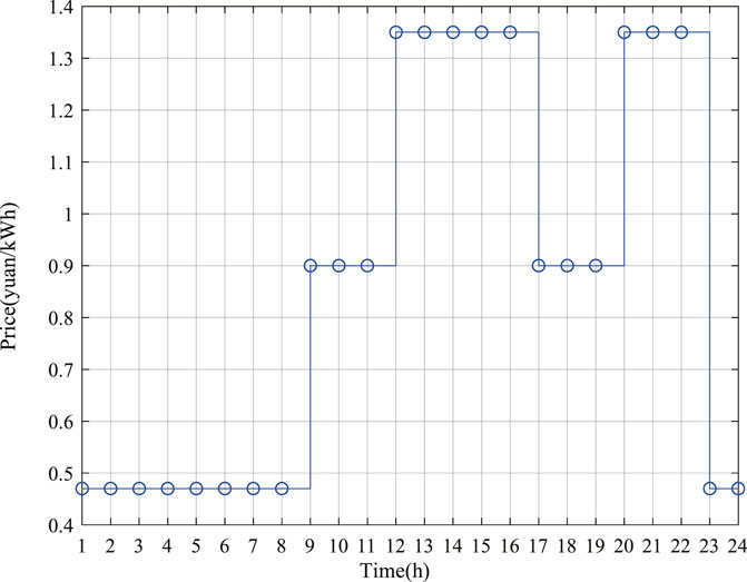
FIGURE 4. Power purchase price of MEFCS.
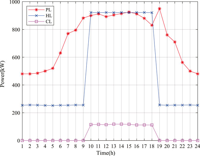
FIGURE 5. Load of MEFCS
5.2 Results Analysis
The output curve of each equipment is shown in Figure 6. It can be seen that the supply of electric energy and heat energy of the system is mainly guaranteed by a gas turbine and heat pump, but only the output of each equipment is not enough to meet the load demand during the peak load period of the system. At this time, the system needs to purchase electricity from the external power grid to jointly supply energy to the load. In addition, it can be seen from the figure that the discharge time of the power storage equipment is 03:00–21:00, and the heat release time of the heat storage equipment is 06:00–19:00. In other periods, that energy storage equipment is in the charged states.
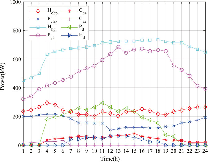
FIGURE 6. Output of each equipment of MEFCS.
While using the multi-objective collaborative optimization model proposed in this paper to solve the multi-energy flow coupling system, three separate objectives are solved respectively. After finding the individual optimization of each objective, its state variables are substituted into the other two objectives to obtain the respective results of the three objectives in this case. The comparison between the operation results of each scheme and the operation results of multi-objective collaborative optimization is shown in Table 1. It can be found from Table 1 that the CO2 emission under multi-objective collaborative optimization increases by 3.8% compared with that under single objective F1 optimization, the system operation cost increases by 6.1% compared with that under single objective F2 optimization, and the primary energy utilization rate decreases by 7.2% compared with that under single objective F3 optimization. Although each objective under multi-objective collaborative optimization is not the optimal solution, the contradiction and conflict between each single objective are balanced in the optimization process. On the premise of taking the minimum carbon emission of the system as the leading objective, the comprehensive satisfaction of the system is significantly higher than the solution results of each single objective, and a relatively satisfactory optimal scheduling scheme is given.

TABLE 1. Comparison between multi-objective collaborative optimization and single-objective optimization.
In order to further compare the differences between the multi-objective collaborative optimization proposed in this paper and the traditional single objective optimization, the optimization results of each single objective and the multi-objective collaborative optimization results are analyzed period by period, as shown in Figure 7. In the figure,
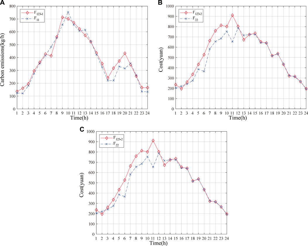
FIGURE 7. Period by period analysis of single objective and multi-objective optimization results. (A) Comparison of environmental protection objectives by period. (B) Period by period comparison of economic objectives. (C) Period by period comparison of energy efficiency objectives.
In order to highlight the effectiveness of the simplified primal dual interior point method proposed in this paper, the particle swarm optimization (PSO) algorithm is selected to compare with the algorithm proposed in this paper. The solution process curves of the simplified primal dual interior point method and particle swarm optimization algorithm for the system comprehensive satisfaction objective are shown in Figures 8A,B, respectively. They tend to converge at the 25th and 65th iterations, respectively. It can be seen that the convergence of the simplified primal dual interior point method is better than that of the particle swarm optimization algorithm. In addition, from the solution results of the two algorithms, it can be seen that the simplified primal dual interior point method finally converges near 0.9685, while the particle swarm optimization algorithm finally converges only near 0.8352, which still has a certain deviation from the global optimal solution. Therefore, the global optimization ability of the simplified primal dual interior point method proposed in this paper is also stronger than that of the particle swarm optimization algorithm.
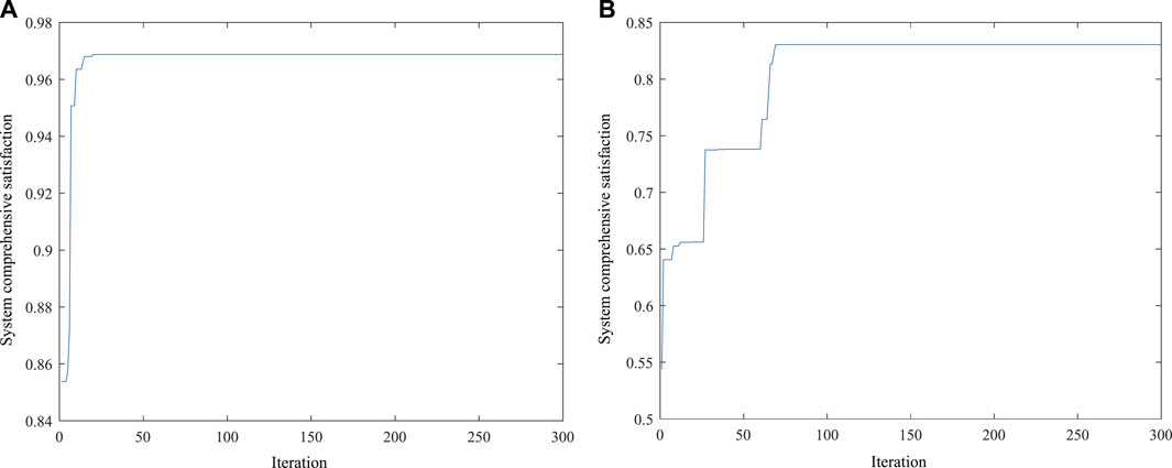
FIGURE 8. Solving process of the comprehensive satisfaction objective for MEFCS. (A) Simplified primal dual interior point method. (B) Particle swarm optimization algorithm.
6 Conclusion
In this paper, the multi-objective collaborative optimization model of MEFCS has been developed considering each of the environmental protection, system economy, and energy efficiency as the objectives of this study, in which the carbon emission orientation goal could be achieved. Moreover, the simplified primal dual interior point method has been used to solve the constructed model. According to the obtained results, the following findings have been concluded: 1) The contradiction and conflict between the three objectives (CO2 emission, system operation cost, and primary energy utilization rate) were relatively balanced under the proposed collaborative optimization operation, which have clearly demonstrated that the satisfaction of collaborative optimization operation considering multiple objectives could be higher than that considering a single objective of the system. 2) Each equipment of the system could achieve stable energy supply as well as continuous output throughout the whole operation process, whereas the working state was difficult to fluctuate sorely. 3) At the same time, the operator could adjust the weight of the three objectives through his own will, so as to get the best operation results that meet his requirements. 4) In addition, the simulation results have illustrated that the simplified primal dual interior point method being adopted in this paper has better convergence and global optimization ability in multi-objective collaborative optimization. However, more investigations are needed regarding the sensitivity analysis on the critical parameters of the multi-energy flow coupling system, which will be considered in our future research work.
Data Availability Statement
The original contributions presented in the study are included in the article/Supplementary Material, further inquiries can be directed to the corresponding author.
Author Contributions
XZ: Methodology, software, writing—original draft, data curation. YY: Conceptualization of this study, supervision, review and editing. HW: Review and editing.
Funding
This work was supported by the National Natural Science Foundation of China (No. 51477041).
Conflict of Interest
The authors declare that the research was conducted in the absence of any commercial or financial relationships that could be construed as a potential conflict of interest.
Publisher’s Note
All claims expressed in this article are solely those of the authors and do not necessarily represent those of their affiliated organizations, or those of the publisher, the editors, and the reviewers. Any product that may be evaluated in this article, or claim that may be made by its manufacturer, is not guaranteed or endorsed by the publisher.
References
Barati, F., Seifi, H., Sepasian, M. S., Nateghi, A., Shafie-khah, M., and Catalao, J. P. S. (2015). Multi-period Integrated Framework of Generation, Transmission, and Natural Gas Grid Expansion Planning for Large-Scale Systems. IEEE Trans. Power Syst. 30 (5), 2527–2537. doi:10.1109/TPWRS.2014.2365705
Clegg, S., and Mancarella, P. (2016). Integrated Electrical and Gas Network Flexibility Assessment in Low-Carbon Multi-Energy Systems. IEEE Trans. Sustain. Energ. 7 (2), 718–731. doi:10.1109/TSTE.2015.2497329
Fan, D., Dou, X., Xu, Y., Wu, C., Xue, G., and Shao, Y. (2021). A Dynamic Multi-Stage Planning Method for Integrated Energy Systems Considering Development Stages. Front. Energ. Res. 9, 723702. doi:10.3389/fenrg.2021.723702
Ghosh, S., and Kamalasadan, S. (2017). An Energy Function-Based Optimal Control Strategy for Output Stabilization of Integrated DFIG-Flywheel Energy Storage System. IEEE Trans. Smart Grid. 8 (4), 1922–1931. doi:10.1109/TSG.2015.2510866
Hu, Q., Liang, Y., Ding, H., Quan, X., Wang, Q., and Bai, L. (2022). Topological Partition Based Multi-Energy Flow Calculation Method for Complex Integrated Energy Systems. Energy. 244, 123152. doi:10.1016/j.energy.2022.123152
Huang, W., Zhang, N., Yang, J., Wang, Y., and Kang, C. (2019). Optimal Configuration Planning of Multi-Energy Systems Considering Distributed Renewable Energy. IEEE Trans. Smart Grid. 10 (2), 1452–1464. doi:10.1109/TSG.2017.2767860
Klyapovskiy, S., You, S., Cai, H., and Bindner, H. W. (2019). Integrated Planning of a Large-Scale Heat Pump in View of Heat and Power Networks. IEEE Trans. Ind. Applicat. 55 (1), 5–15. doi:10.1109/TIA.2018.2864114
Koltsaklis, N. E., and Knápek, J. (2021). Optimal Scheduling of a Multi-Energy Microgrid. Chem. Eng. Trans. 88, 901–906. doi:10.3303/CET2188150
Li, C., Yang, H., Shahidehpour, M., Xu, Z., Zhou, B., Cao, Y., et al. (2020). Optimal Planning of Islanded Integrated Energy System with Solar-Biogas Energy Supply. IEEE Trans. Sustain. Energ. 11 (4), 2437–2448. doi:10.1109/TSTE.2019.2958562
Liu, N., Wang, J., and Wang, L. (2019). Hybrid Energy Sharing for Multiple Microgrids in an Integrated Heat-Electricity Energy System. IEEE Trans. Sustain. Energ. 10 (3), 1139–1151. doi:10.1109/TSTE.2018.2861986
Luo, Z., Gu, W., Wu, Z., Wang, Z., and Tang, Y. (2018). A Robust Optimization Method for Energy Management of CCHP Microgrid. J. Mod. Power Syst. Clean. Energ. 6 (1), 132–144. doi:10.1007/s40565-017-0290-3
Ma, T., Wu, J., Hao, L., Lee, W.-J., Yan, H., and Li, D. (2018). The Optimal Structure Planning and Energy Management Strategies of Smart Multi Energy Systems. Energy. 160, 122–141. doi:10.1016/j.energy.2018.06.198
Nicolosi, F. F., Alberizzi, J. C., Caligiuri, C., and Renzi, M. (2021). Unit Commitment Optimization of a Micro-grid with a MILP Algorithm: Role of the Emissions, Bio-Fuels and Power Generation Technology. Energ. Rep. 7, 8639–8651. doi:10.1016/j.egyr.2021.04.020
Qu, M., Ding, T., Jia, W., Zhu, S., Yang, Y., and Blaabjerg, F. (2021). Distributed Optimal Control of Energy Hubs for Micro-integrated Energy Systems. IEEE Trans. Syst. Man. Cybern, Syst. 51 (4), 2145–2158. doi:10.1109/TSMC.2020.3012113
Shen, F., Zhao, L., Du, W., Zhong, W., and Qian, F. (2020). Large-scale Industrial Energy Systems Optimization under Uncertainty: A Data-Driven Robust Optimization Approach. Appl. Energ. 259, 114199. doi:10.1016/j.apenergy.2019.114199
Sirvent, M., Kanelakis, N., Geissler, B., and Biskas, P. (2017). Linearized Model for Optimization of Coupled Electricity and Natural Gas Systems. J. Mod. Power Syst. Clean. Energ. 5 (3), 364–374. doi:10.1007/s40565-017-0275-2
Sun, Y., Zhang, B., Ge, L., Sidrov, D., Wang, J., and Xu, Z. (2020). Day-ahead Optimization Schedule for Gas-Electric Integrated Energy System Based on Second-Order Cone Programming. Csee Jpes. 6 (1), 142–151. doi:10.17775/CSEEJPES.2019.00860
Wang, D., Zhi, Y., Zhi, Y., Yu, B., Chen, Z., An, Q., et al. (2018). Optimal Coordination Control Strategy of Hybrid Energy Storage Systems for Tie-Line Smoothing Services in Integrated Community Energy Systems. Csee Jpes. 4 (4), 408–416. doi:10.17775/CSEEJPES.2017.01050
Wang, Y., Zhang, N., Zhuo, Z., Kang, C., and Kirschen, D. (2018). Mixed-integer Linear Programming-Based Optimal Configuration Planning for Energy Hub: Starting from Scratch. Appl. Energ. 210, 1141–1150. doi:10.1016/j.apenergy.2017.08.114
Wang, L., Hou, C., Ye, B., Wang, X., Yin, C., and Cong, H. (2021). Optimal Operation Analysis of Integrated Community Energy System Considering the Uncertainty of Demand Response. IEEE Trans. Power Syst. 36 (4), 3681–3691. doi:10.1109/TPWRS.2021.3051720
Wang, W., Huang, S., Zhang, G., Liu, J., and Chen, Z. (2021). Optimal Operation of an Integrated Electricity-Heat Energy System Considering Flexible Resources Dispatch for Renewable Integration. J. Mod. Power Syst. Cle. 9 (4), 699–710. doi:10.35833/MPCE.2020.000917
Wang, Y., Li, R., Dong, H., Ma, Y., Yang, J., Zhang, F., et al. (2019). Capacity Planning and Optimization of Business Park-Level Integrated Energy System Based on Investment Constraints. Energy. 189, 116345. doi:10.1016/j.energy.2019.116345
Wu, J., Li, B., Chen, J., Ding, Y., Lou, Q., Xing, X., et al. (2021). Multi-objective Optimal Scheduling of Offshore Micro Integrated Energy System Considering Natural Gas Emission. Int. J. Electr. Power Energ. Syst. 125, 106535. doi:10.1016/j.ijepes.2020.106535
Xiao, H., Pei, W., Pei, W., Dong, Z., and Kong, L. (2018). Bi-level Planning for Integrated Energy Systems Incorporating Demand Response and Energy Storage under Uncertain Environments Using Novel Metamodel. Csee Jpes. 4 (2), 155–167. doi:10.17775/CSEEJPES.2017.01260
Yang, J., Zhang, N., Kang, C., and Xia, Q. (2018). Effect of Natural Gas Flow Dynamics in Robust Generation Scheduling under Wind Uncertainty. IEEE Trans. Power Syst. 33 (2), 2087–2097. doi:10.1109/TPWRS.2017.2733222
Zhang, S., Gu, W., Yao, S., Lu, S., Zhou, S., and Wu, Z. (2021). Partitional Decoupling Method for Fast Calculation of Energy Flow in a Large-Scale Heat and Electricity Integrated Energy System. IEEE Trans. Sustain. Energ. 12 (1), 501–513. doi:10.1109/TSTE.2020.3008189
Zhao, B., Conejo, A. J., and Sioshansi, R. (2018). Coordinated Expansion Planning of Natural Gas and Electric Power Systems. IEEE Trans. Power Syst. 33 (3), 3064–3075. doi:10.1109/TPWRS.2017.2759198
Zhou, Z., Liu, P., Li, Z., and Ni, W. (2013). An Engineering Approach to the Optimal Design of Distributed Energy Systems in China. Appl. Therm. Eng. 53 (2), 387–396. doi:10.1016/j.applthermaleng.2012.01.067
Glossary
Acronyms
AHP Analytic hierarchy process
AR Absorption refrigerator
BD Benders decomposition
CHP Combined heating and power
DRE Distributed renewable energy
EES Electric energy storage
ER Electric refrigerator
FRs Flexible resources
GT Gas turbine
HP Heat pump
HES Heat energy storage
IEHES Integrated electricity-heat energy system
MEFCS Multi-energy flow coupling system
OCCS Optimal coordination control strategy
PV Photovoltaic
SOCP Second-order cone programming
WHB Waste heat boiler
WT Wind turbine
Parameters
K Power temperature coefficient
N Total amount of equipment
Variables
Keywords: multi-energy flow coupling system, multi-objective collaborative optimization, combined weighting method, simplified primal-dual interior point algorithm, carbon emission
Citation: Zong X, Yuan Y and Wu H (2022) Multi-Objective Optimization of Multi-Energy Flow Coupling System With Carbon Emission Target Oriented. Front. Energy Res. 10:877700. doi: 10.3389/fenrg.2022.877700
Received: 17 February 2022; Accepted: 28 March 2022;
Published: 10 May 2022.
Edited by:
Qingxin Shi, North China Electric Power University, ChinaReviewed by:
Linquan Bai, University of North Carolina at Charlotte, United StatesNikolaos Koltsaklis, Czech Technical University in Prague, Czechia
Zhenkun Li, Shanghai University of Electric Power, China
Copyright © 2022 Zong, Yuan and Wu. This is an open-access article distributed under the terms of the Creative Commons Attribution License (CC BY). The use, distribution or reproduction in other forums is permitted, provided the original author(s) and the copyright owner(s) are credited and that the original publication in this journal is cited, in accordance with accepted academic practice. No use, distribution or reproduction is permitted which does not comply with these terms.
*Correspondence: Xuanjun Zong, em9uZ3h1YW5qdW5AMTYzLmNvbQ==