 Qiankun Hu
- School of Intelligent Manufacturing, Huanghuai University, Zhumadian, China
The influence of electromechanical power on the power system is controlled in order to stabilize the power system. The author establishes a fourth-order power system model with a power disturbance term based on the dissipative property; the possibility of the existence of a system chaotic attractor is analyzed using the Lyapunov exponent spectrum, bifurcation diagram, phase diagram, spectral entropy, etc., and the influence of the power disturbance term on the motion state of the system is studied. It can be seen that under the influence of the disturbance frequency, the system will exhibit sufficient dynamic behavior. The parameters of the power disturbance term are more sensitive to the influence of the system power angle, and when the disturbance amplitude reaches a certain value, the power angle will increase sharply, and eventually the system will become unstable. The experimental results show that when controller parameters
1 Introduction
Chaos is the seemingly random motion that occurs in deterministic systems. It is the main direction of nonlinear research and generally exists in all macroscopic and microscopic systems of the universe (Wang et al., 2017). At present, chaos theory has penetrated mathematics, physics, chemistry, electronics, information science, biology, geology, meteorology, and cosmology, as well as economics and human brain science, and almost all natural and humanistic fields such as music, art, and sports. Therefore, the chaos theory has a high theoretical research value and practical application value (Bi et al., 2016). The power system is a dynamic system with strong coupling, high nonlinearity, and multiple parameters. Its dynamic behavior exhibits many complex nonlinear electromechanical oscillation phenomena. When the system is running normally, it exhibits periodic oscillation (Hou et al., 2021). With the rapid development of large-scale power systems characterized by large units and ultra-high voltage grids, there is a potential threat to the safe operation of the system. Various emergencies and uncertain factors cause continuous and irregular oscillations of the system operating parameters, and chaos often occurs in the actual operation of the power system. In severe cases, the power system may become unstable or even collapse, thereby causing large-scale power outages. The control strategies are aimed at precise integer-order mathematical models, and, in the actual power system, are influenced by external factors and the nature of the system itself. There are uncertainties in system parameters and external disturbances; in particular, new energy and distributed generation are increasingly being introduced into the grid, which further increases the uncertainty of the power system (Wang et al., 2019). These uncertainties easily cause chaotic oscillation of the system and seriously affect the stability of the power system (Zhao and Kamwa, 2020). On the other hand, integer-order systems are approximate idealizations of fractional-order systems. The fractional-order power systems are mainly based on chaotic synchronization. In particular, there is less research on chaos control under uncertain factors, there are not many researches based on chaos control. Figure 1 shows the physical model of power oscillation. Therefore, for integer-order and fractional-order power system models, considering the influence of internal parameters and uncertain factors of the system, it is necessary to study the chaos control strategy. This will provide the scientific basis and reference data for early warning and processing of the power system's chaotic oscillation. Relative to the relationship between the state variables of the system and input variables, for a linear system that satisfies the superposition principle, the nonlinear system is a kind of irregular motion and is ubiquitous in nature, with the most important motion behavior being the chaotic motion (Preece and Milanovic, 2016). The definition of chaos has not yet reached a consensus in the industry and its expression is complex, with disorder and irregularity; it is often manifested as a nonlinear system under certain conditions and exhibits unpredictable phenomena. It is a manifestation of the fusion of variability and immutability, the presence or absence of sequences or rules. Chaotic motion is neither an invisible phenomenon nor a phenomenon that can be seen by the naked eye. It can be observed only with the help of advanced instruments. It is ubiquitous in the motion state of all things in the universe, and this phenomenon can be observed every day in life (Banerjee et al., 2018; Luo et al., 2020). For example, from the lit blue smoke that suddenly tumbles irregularly after rising and finally dissipates, to the calm stock market that becomes suddenly chaotic because of a stock change, and also the sputtering of water droplets, whose state trajectory is a chaotic phenomenon. Since the 1960s, there have been more and more studies on chaos. It has developed into a very huge discipline system, radiating to physics, economics, finance, meteorology, biology, sociology and other disciplines. At present, the research of various chaos theories will affect the development of modern discipline system, radiation to physics, economics and finance, meteorology, biology, sociology, and other disciplines, and now, every kind of chaos theory research will affect the further development of this modern disciplinary system.
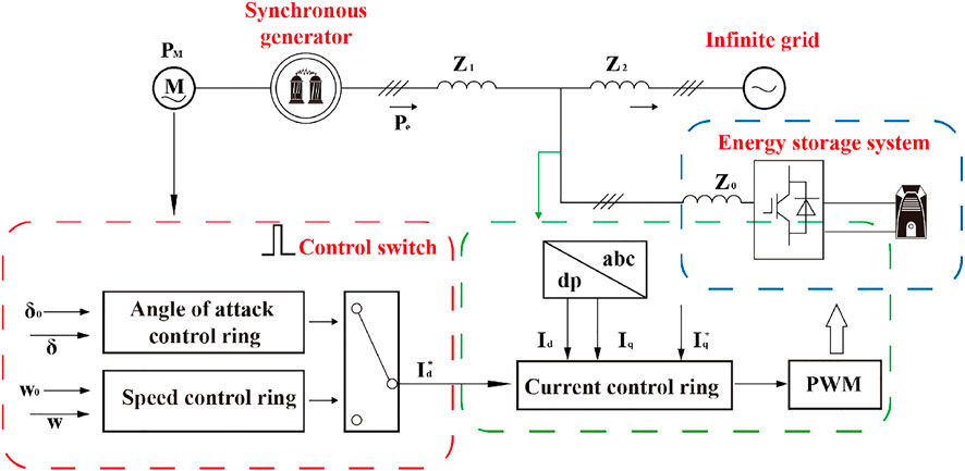
FIGURE 1. Physical model of power oscillation.
The author proposes a study on the chaotic oscillation control model of the power system under electromechanical power disturbance and establishes a fourth-order power system model with a power disturbance term based on the dissipative property; the possibility of the existence of a system chaotic attractor is analyzed using the Lyapunov exponent spectrum, bifurcation diagram, phase diagram, spectral entropy, etc., and the influence of the power disturbance term on the motion state of the system is studied. It can be seen that under the influence of the disturbance frequency, the system will exhibit sufficient dynamic behavior. The parameters of the power disturbance term are more sensitive to the influence of the system power angle, and when the disturbance amplitude reaches a certain value, the power angle will increase sharply and eventually the system will become unstable.
2 Literature Review
In response to this research problem, Liu et al. (2017) proposed the scientific concept of chaos, which is an important achievement in nonlinear science in recent years. Zhang et al. (2015) proposed a method to calculate the Lyapunov index of a system from a time series, moving chaos research from the theoretical stage to the practical application stage. Errouissi et al. (2017) proposed the OGY control method. Since then, researchers have continued to discover new chaotic systems and hyperchaotic systems, and chaos control has become a new hot spot in chaos research. Besselmann et al. (2016) established a simple power system model and proved that the system will exhibit chaotic oscillation. Mishra et al. (2021) studied in detail the case of considering and ignoring the damping winding, a bifurcation phenomenon in a three-node power system. Since then, the research on chaos control of power system has sprung up. As the world's largest energy producer and consumer, China's goal is the safe and stable operation of power system, which further promotes the in-depth study of power system control theory. Based on a simple interconnected power system model, Shen et al. (2020) analyzed the chaos generation mechanism of a three-parameter system. Zhang et al. (2020) focused on the analysis of its chaotic phenomenon for the classical generator rocking equation. Mousakazemi (2019) studied the chaotic phenomenon of a power system under different instability modes, and, for the first time, two kinds of instability phenomena were found in the ruptured state of the chaotic limit cycle: system angular instability as well as simultaneous voltage and angular instability. Qin et al. (2018) reviewed several bifurcation phenomena in power systems and introduced the application of the chaos theory in short-term load forecasting of power systems. Wang et al. (2020) adopted a nonlinear feedback control method, an active feedback control method, and control research on fractional-order power system chaos. Overbye and Klump (2015) used the fuzzy sliding mode control method to suppress the chaos of the power system and reduce chattering to a certain extent. The authors proposed a study on the chaotic oscillation control model of a power system under electromechanical power disturbance, established a fourth-order power system model with a power disturbance term based on the dissipative property, analyzed the possibility of the existence of a system chaotic attractor using the Lyapunov exponent spectrum, bifurcation diagram, phase diagram, spectral entropy, etc., and studied the influence of the power disturbance term on the motion state of the system, where it can be seen that under the influence of the disturbance frequency, the system will exhibit sufficient dynamic behavior. The parameters of the power disturbance term are more sensitive to the influence of the system power angle, and when the disturbance amplitude reaches a certain value, the power angle will increase sharply and eventually the system will become unstable. The experimental results show that when the controller parameters
3 Methods
3.1 System Modeling
The output voltage
In the above equation,
In the power system, the excitation link of the terminal amplitude limiting method is generally used to protect the equipment of the system, and the output voltage
When the input voltage
The parameter values are shown in Table 1. The dissipation characteristics of Equation (1) can be calculated as shown in Equation (4):
Corresponding to time t, V is always shrinking during the movement, as shown in Equation (5). This shows the possibility of the existence of chaotic attractors in the system.
At the same time, by substituting the system parameter values in Table 1, the algebraic equation shown in Equation 6 can be obtained (Stankovic et al., 2015).
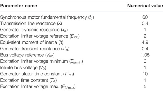
TABLE 1. System parameter values.
Among these, the output voltage
The voltage V is expressed as
By setting a set of system parameters d = 0.5,
To set the simulated environment parameters, system parameters D = 2,
3.2 Influence of the Power Disturbance Term on the System
We will substitute
3.2.1 Disturbance Amplitude
The presence of the electromagnetic disturbance term may cause the system to appear ultra-high voltage, which affects the stable operations of the system, therefore it is necessary to study the electromagnetic disturbance term. When
When

TABLE 2. LE and system status at different
3.2.2 Electromagnetic Disturbance Frequency
Frequency, another important parameter of power disturbance, will also directly affect the motion state of the power system. Without considering the load disturbance and choosing in the range of
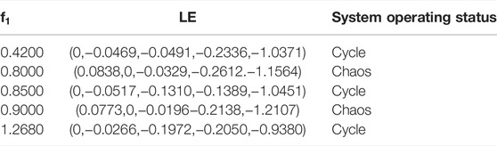
TABLE 3. LE and system states at different
3.2.3 Load Disturbance Amplitude
The presence of load disturbances may cause problems such as harmonics and voltage fluctuations that impair power quality and threaten the stability of the power system; therefore, it is necessary to study the load disturbance term. Without considering the electromagnetic disturbance,
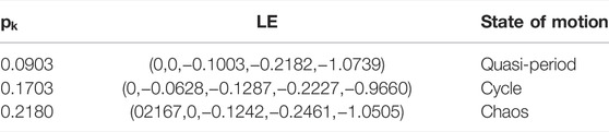
TABLE 4. LE and system status at different
3.2.4 Load Disturbance Frequency
Similar to the above analysis method, without considering electromagnetic disturbance,
When compared to the situation of changing A, changing B brings about similar changes to the system and there are only a few minor differences. When

TABLE 5. LE and system status at different
4 Results and Analysis
The system parameters D = 2,
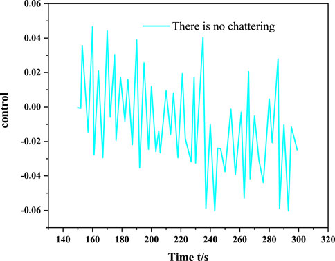
FIGURE 2. Sliding mode control with target trajectory r = 1.2 + 0.1 sin(t).
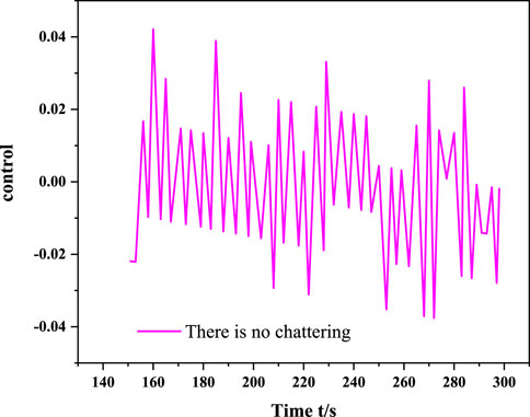
FIGURE 3. Sliding mode control with target trajectory r = 1.2.
The symbolic function
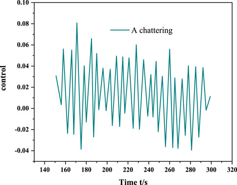
FIGURE 4. Sliding mode control of target trajectory r = 1.2 + 0.1 sin(t) using a sign function.
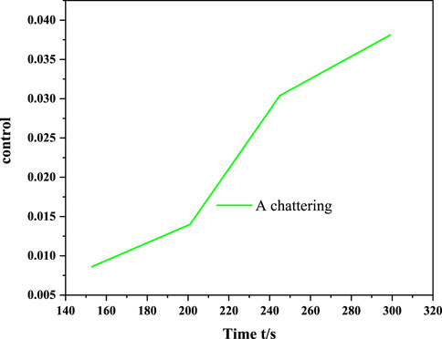
FIGURE 5. Sliding mode control with a sign function for the target trajectory r = 1.2.
5 Conclusion
This article proposes a chaotic oscillation control model of the power system under electromechanical power interference. The author proposes a study on the chaotic oscillation control model of a power system under electromechanical power disturbance. By establishing a fourth-order power system model with a power disturbance term, the Lyapunov exponent, bifurcation diagram, and spectral entropy are analyzed and the influence of the power disturbance term on the motion state of the power system is discussed. The simulation results show that the controller can quickly and smoothly suppress the chaotic oscillation of the system, and at the same time, it can effectively avoid the chattering problem and has strong robustness. Chaos control is one of the frontiers of nonlinear research, and the systematization and control methods of the chaos theory still need to be improved. Second, the majority of researchers should consider the engineering realization of chaos control. A large number of simulation experiments have theoretically proved the effectiveness of the control strategy but there is still a certain distance from being widely used in engineering applications. Therefore, researchers have to conduct in-depth research and engineering experiments and use interdisciplinary research methods for referencing to form practical research results.
Data Availability Statement
The original contributions presented in the study are included in the article/Supplementary Material, and further inquiries can be directed to the corresponding author.
Author Contributions
The author confirms being the sole contributor to this work and has approved it for publication.
Conflict of Interest
The author declares that the research was conducted in the absence of any commercial or financial relationships that could be construed as a potential conflict of interest.
Publisher’s Note
All claims expressed in this article are solely those of the authors and do not necessarily represent those of their affiliated organizations, or those of the publisher, the editors, and the reviewers. Any product that may be evaluated in this article, or claim that may be made by its manufacturer, is not guaranteed or endorsed by the publisher.
References
Alam, M. R., Bai, F., Yan, R., and Saha, T. K. (2020). Classification and Visualization of Power Quality Disturbance-Events Using Space Vector Ellipse in Complex Plane. IEEE Trans. Power Deliv. 36 (99), 1. doi:10.1109/TPWRD.2020.3008003
Banerjee, A., Chaudhuri, N. R., and Kavasseri, R. G. (2018). A Novel Explicit Disturbance Model-Based Robust Damping of Inter-area Oscillations through Mtdc Grids Embedded in Ac Systems. IEEE Trans. Power Deliv. 33, 1. doi:10.1109/tpwrd.2018.2799170
Besselmann, T. J., Almér, S., and Ferreau, H. J. (2016). Model Predictive Control of Load-Commutated Inverter-Fed Synchronous Machines. IEEE Trans. Power Electro. 31 (10), 7384–7393. doi:10.1109/TPEL.2015.2511095
Bi, T., Qin, J., Yan, Y., Liu, H., and Martin, K. E. (2016). Disturbance Propagation Mechanism Based on the Electromechanical Wave Theory. IET Generation, Transm. Distribution 10 (12), 2891–2898. doi:10.1049/iet-gtd.2015.1268
Dong, K., Shi, T., Xiao, S., Li, X., and Xia, C. (2018). A Finite Set Model Predictive Control Method for Quasi-Z Source Inverter-Permanent Magnet Synchronous Motor Drive System. IET Electric Power Appl. 13 (3), 302–309.
Errouissi, R., Al‐Durra, A., Muyeen, S. M., and Leng, S. (2017). Continuous‐time Model Predictive Control of a Permanent Magnet Synchronous Motor Drive with Disturbance Decoupling. Iet Electric Power Appl. 11 (5), 697–706. doi:10.1049/iet-epa.2016.0499
Hou, G., Ke, Y., and Huang, C. (2021). A Flexible Constant Power Generation Scheme for Photovoltaic System by Error-Based Active Disturbance Rejection Control and Perturb & Observe. Energy 237 (9), 121646. doi:10.1016/j.energy.2021.121646
Liu, H., Loh, P. C., Wang, X., Yang, Y., Wang, W., and Xu, D. (2016). Droop Control with Improved Disturbance Adaption for a Pv System with Two Power Conversion Stages. IEEE Trans. Ind. Electron. 63 (10), 6073–6085. doi:10.1109/tie.2016.2580525
Liu, Z., Miao, S., Fan, Z., and Han, J. (2017). Markovian Switching Model and Non‐linear DC Modulation Control of AC/DC Power System. IET Generation, Transm. Distribution 11 (10), 2654–2663. doi:10.1049/iet-gtd.2016.1862
Luo, S., Lewis, F. L., Song, Y., and Ouakad, H. M. (2020). Accelerated Adaptive Fuzzy Optimal Control of Three Coupled Fractional-Order Chaotic Electromechanical Transducers. IEEE Trans. Fuzzy Syst. 29 (99), 1. doi:10.1109/TFUZZ.2020.2984998
Mishra, D., Singh, B., and Panigrahi, B. K. (2021). Adaptive Current Control for a Bidirectional Interleaved Ev Charger with Disturbance Rejection. IEEE Trans. Industry Appl. 57 (99), 1. doi:10.1109/tia.2021.3074612
Mousakazemi, S. M. H. (2019). Control of a Pwr Nuclear Reactor Core Power Using Scheduled Pid Controller with ga, Based on Two-point Kinetics Model and Adaptive Disturbance Rejection System. Ann. Nucl. Energ. 129 (JUL), 487–502. doi:10.1016/j.anucene.2019.02.019
Overbye, T. J., and Klump, R. P. (2015). Determination of Emergency Power System Voltage Control Actions. IEEE Trans. Power Syst. 13 (1), 205–210. doi:10.1109/59.651637
Preece, R., and Milanovic, J. V. (2016). Efficient Estimation of the Probability of Small-Disturbance Instability of Large Uncertain Power Systems. IEEE Trans. Power Syst. 31 (2), 1063–1072. doi:10.1109/tpwrs.2015.2417204
Qin, J., Bi, T., Liu, H., and Martin, K. E. (2018). Model Approach of Power Networks Based on Unsymmetrical Inertia Distribution for Disturbance Propagation Study. IET Generation, Transm. Distribution 12 (9), 2055–2064. doi:10.1049/iet-gtd.2017.1243
Ramanathan, B., and Vittal, V. (2015). Small-disturbance Angle Stability Enhancement through Direct Load Control Part Ii-Numerical Simulations and Results. IEEE Trans. Power Syst. 21 (2), 782–790. doi:10.1109/TPWRS.2006.873025
Shen, J., Li, W. D., Liu, L., Jin, C., and Wang, X. (2020). Frequency Response Model and its Closed-form Solution of Two-Machine Equivalent Power System. IEEE Trans. Power Syst. 36 (99), 1. doi:10.1109/TPWRS.2020.3037695
Silva, L. R. M., Kapisch, E. B., Martins, C. H. N., Filho, L. M. A., Cerqueira, A. S., Duque, C. A., et al. (2017). Gapless Power-Quality Disturbance Recorder. IEEE Trans. Power Deliv. 32 (2), 862–871. doi:10.1109/tpwrd.2016.2557280
Stankovic, A. M., Dukic, S. D., and Saric, A. T. (2015). Approximate Bisimulation-Based Reduction of Power System Dynamic Models. IEEE Trans. Power Syst. 30 (3), 1252–1260. doi:10.1109/tpwrs.2014.2342504
Wang, D., Ma, N., and Guo, C. (2017). Characteristics of Electromechanical Disturbance Propagation in Non‐uniform Power Systems. IET Generation, Transm. Distribution 11 (8), 1919–1925. doi:10.1049/iet-gtd.2016.1126
Wang, F., He, L., and Rodriguez, J. (2020). Fpga-based Continuous Control Set Model Predictive Current Control for Pmsm System Using Multistep Error Tracking Technique. IEEE Trans. Power Electron. 35 (12), 13455–13464. doi:10.1109/tpel.2020.2984336
Wang, L., Liang, H. R., Prokhorov, A. V., Mokhlis, H., and Huat, C. K. (2019). Modal Control Design of Damping Controllers for Thyristor-Controlled Series Capacitor to Stabilize Common-Mode Torsional Oscillations of a Series-Capacitor Compensated Power System. IEEE Trans. Industry Appl. 55, 1. doi:10.1109/tia.2019.2892343
Zhang, R., Xu, Y., Dong, Z. Y., and Wong, K. P. (2015). Post‐disturbance Transient Stability Assessment of Power Systems by a Self‐adaptive Intelligent System. IET Generation, Transm. Distribution 9 (3), 296–305. doi:10.1049/iet-gtd.2014.0264
Zhang, Y., Jiang, T., and Jiao., J. (2020). Model-free Predictive Current Control of Dfig Based on an Extended State Observer under Unbalanced and Distorted Grid. IEEE Trans. Power Electron. 35 (8), 8130–8139. doi:10.1109/tpel.2020.2967172
Keywords: electromechanical power, power system, chaotic oscillation, control, model
Citation: Hu Q (2022) Chaotic Oscillation Control Model of Power System Under Electromechanical Power Disturbance. Front. Energy Res. 10:887561. doi: 10.3389/fenrg.2022.887561
Received: 01 March 2022; Accepted: 22 March 2022;
Published: 14 April 2022.
Edited by:
Fadi AL-Turjman, Near East University, CyprusReviewed by:
Auwalu Mubarak, Near East University, CyprusMin Cai, Xuzhou University of Technology, China
Zhongqiang Zhang, Xuzhou University of Technology, China
Copyright © 2022 Hu. This is an open-access article distributed under the terms of the Creative Commons Attribution License (CC BY). The use, distribution or reproduction in other forums is permitted, provided the original author(s) and the copyright owner(s) are credited and that the original publication in this journal is cited, in accordance with accepted academic practice. No use, distribution or reproduction is permitted which does not comply with these terms.
*Correspondence: Qiankun Hu, aHVxaWFua3VuQGh1YW5naHVhaS5lZHUuY24=