 Yang Hao
 Jia Hao1
- 1The Province Key Lab of Fluid Transmission Technology, Zhejiang Sci-Tech University, Hangzhou, China
- 2Hefei General Machinery Research Institute, Hefei, China
In recent years, much attention has been paid to the application of high-speed centrifugal pumps; still, the development of this pump faces several challenges. In order to obtain a more comprehensive understanding of the high-speed centrifugal pump, this paper reviewed the engineering application, technical challenges, and feasible solutions of this pump from the aspects of hydraulic design, including cavitation, hydraulic excitation, efficiency issue at an ultra-low specific speed, and the solution to these problems. The current state of the structural design of the high-speed centrifugal pump was briefly described in addition. For the faults in the existing high-speed centrifugal pump, some research studies on pump monitoring were presented. Finally, the status and shortcomings of the design of the pump were simply analyzed and summarized. It is hoped that this study can provide some references for the design and practical usage of high-speed centrifugal pumps.
Introduction
Energy demand has been increasing with the acceleration of global industrialization. Electric power is the most widely used secondary energy, which plays a very important role in the development of society. At present, most of the electric power supply systems in the world have adopted the centralized power supply mode of large unit power generation and large grid interconnection. There are three ways to generate large-scale electric energy: coal-fired electric power generation, heavy-duty gas turbine and its combined cycle electric power generation, and nuclear electric power generation. As an important mode of thermal power generation, heavy-duty gas turbine and its combined cycle power generation take gas as a high-temperature working medium, steam as a low-temperature working medium, and the gas turbine exhaust as the heating source for power supply, as shown in Figure 1.
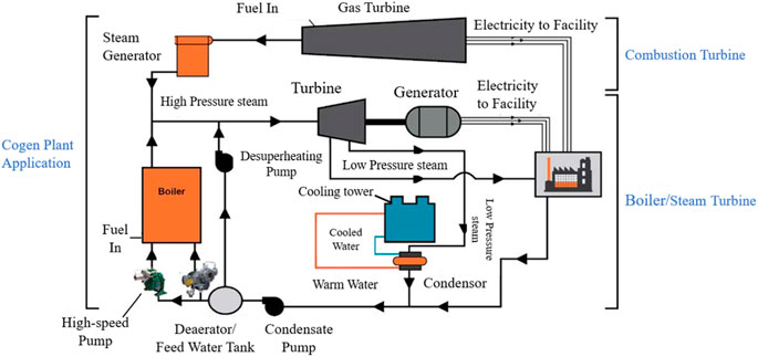
FIGURE 1. Power system (2011).
The transmission of medium is the premise of stable operation of the power supply system, which is achieved by the pump. A high-speed centrifugal pump has the characteristics of small volume and high head, which is often used for the transportation of the condensate in the system. The structure of a high-speed centrifugal pump, as shown in Figure 2, is mainly constructed by the motor, gearbox, and pump. The working principle of high-speed centrifugal pumps is similar to that of the ordinary centrifugal pump, but it obtains a high speed through the gearbox (Anmin Zhou, 2021).
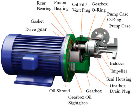
FIGURE 2. Structure of the high-speed centrifugal pump (2011).
High head and high speed are the characteristics of a high-speed pump. However, its defects cannot be ignored. It is prone to cavitation, and the excitation problem is more serious (Berten, 2009; Huimin Li, 2019). At the same time, the inefficient problem will also have a great impact on the operation of the pump (Zuchao Zhu, 2007; Kraeva, 2010). In addition, the structural design also affects the performance of the pump. Thus, researchers have conducted in-depth research on the hydraulic design and structural improvement of high-speed centrifugal pumps. In this work, a comprehensive review concerning high-speed centrifugal pumps is discussed. Hydraulic Design of High-Speed Centrifugal Pumps elaborates on the hydraulic design of the pump, which includes the research on cavitation, pressure pulsation, and inefficient problem. Structural Design of High-Speed Centrifugal Pump describes the current state of the pump’s structural design. Vibration Monitoring System describes the pump fault diagnosis, and conclusions are presented in Conclusion.
Hydraulic Design of High-Speed Centrifugal Pumps
The hydraulic problem is an important consideration in the design and operation of high-speed centrifugal pumps, which seriously restricts the development of pumps. It is closely related to the flow phenomena. Some feasible schemes are put forward by analyzing these phenomena.
Cavitation
Cavitation is widely seen in high-speed centrifugal pumps. It will be generated when the absolute pressure of the liquid is lower than the vaporization pressure. The phenomenon will be different with different fluid media when cavitation occurs, which means that the impact on the pump is also different (Songsheng Deng, 2019). Generally, a low-pressure area appears when the backflow vortex occurs at the pump inlet, and the velocity is high and fluctuates greatly. As to the mechanism of the backflow, Stepanoff (J, 1947) pointed out that the inertial force of the liquid increases the circular velocity of the liquid around the blade when the flow rate decreases to near zero. This eliminates the energy gradient necessary to maintain the flow, resulting in backflow. Fraser (Warren, 1981) held that the pressure gradient at some points is reversed when the dynamic head exceeds the centrifugal head, which may cause backflow. It is found that the backflow vortex in the inlet section is caused by the liquid flow near the outer edge of the blades. For backflow, Shuai Hu (2017) found that the backflow vortex is mainly related to the flow rate under the condition of low flow rate. Zhao J (2014) showed that there are four types of vortices in the impeller channel, as shown in Figure 3. It is clear that type C occupies the largest space, causing the main flow problem.
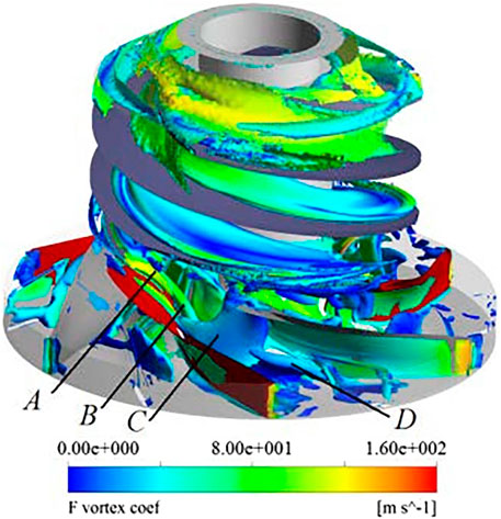
FIGURE 3. Vortex core in the inducer-impeller (Zhao J, 2014).
In addition, the low-pressure area is related to the liquid inlet pressure and temperature. Hu’s (Zhao J, 2014) simulation results showed that the low-pressure area gradually expands with the decrease in the inlet total pressure. Jin Jiang (2019) found that the bubbles in the impeller passage will suddenly increase when the temperature is greater than 90°C, while the increasing trend will weaken after the temperature is greater than 90°C.
Cavitation will have a great impact on the head. The head would drop precipitously when the cavitation coefficient decreases to a certain value (Xu Luo, 2018).
Inducer Design
At present, the most widely used solution to the cavitation problem is to add an inducer in front of the impeller. Debarpan Paul (2020) pointed out that the inducer is the most effective at the operating range of the pump and tends to lose its function under off-designed conditions. The type, structure, head, and installation position of the inducer all affect the anti-cavitation ability of the pump.
The anti-cavitation ability can be improved by selecting a reasonable type of the inducer type. The velocity pre-spinning at the exit of the splitter blade inducer weakens the backflow, but flow blockage occurred in the splitter blade inducer with the flow rate increase. Xilong Huang (2020) calculated the cavitation number of different inducers under different flow rates. It can be seen from Figure 4 that the splitter blade inducer is suitable for small flow rates, and the variable pitch inducer is better for large flow rates.
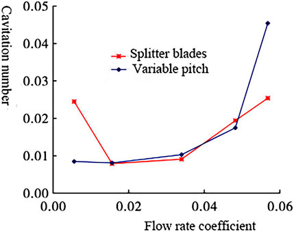
FIGURE 4. Curves of NPSH with the flow coefficient (Xilong Huang, 2020).
In terms of the structure of the inducer, Xiaorui Cheng (2020) proposed that the change of the inducer inclination angle has a great influence on the anti-cavitation ability. It is found that the volume fraction of the gas phase in the inducer is the minimum when θ = 2°. The outlet pitch of the inducer has a significant effect on the cavitation. Guohong Wu (2016) pointed out that increasing the outlet pitch of the inducer can decrease the circumferential velocity of the inducer outlet, and the fluid obtains more pressure energy. At the same time, it can reduce the impeller axial clearance of the low-pressure zone. The anti-cavitation ability of the inducer can be improved by changing the surface of the inducer blade. Huimin Li (2019) cut slots on the inducer and divided the large cavitation of the inducer into several small cavitations, which improves the anti-cavitation ability of the inducer. For the splitter blade inducer, Xiaomei Guo (2012) pointed out that the position of the short blade had a significant effect on cavitation. The optimum position of the short blade in the inducer is L= 0.45 D. For the position of the inducer, the relative angle of the inducer and impeller has a great influence on the efficiency and cavitation capacity. The gas phase ratio between the inducer and impeller varies significantly with the circumferential angle (Baofeng Yang, 2019). The inducer will produce a head. On the basis that no cavitation occurs in the impeller, the higher the head of the inducer, the greater is the inlet pre-spinning of the impeller, and the worse is the cavitation resistance of the impeller (Huimin Li, 2020).
Impeller Design
As the core structure of the pump, the internal flow state of the impeller directly affects the performance of the pump. The anti-cavitation ability can be enhanced by the design of the impeller.
The axial clearance of the blade has a significant effect on the cavitation. Lihong Zhang (2016) found that the low-pressure area at the blade’s back disappears with the increase in axial clearance, which enhances the anti-cavitation ability. The type of blade also affects the cavitation of the pump. The impeller blades are divided into two types: split blades and full blades. At a low flow rate, the blockage of the passage will decrease the inner pressure of the impeller. Jianping Yuan (2014) found that cavitation occurs in all passages of the 4 + 4 split blade pump, and part of the cavitation is serious, while the cavitation has not appeared in the full blades. The anti-cavitation ability can be improved by adding a balance hole on the impeller. The air bubble accumulates in the balance hole, which is then sheared away by the high-pressure fluid at the outlet of the impeller to improve the anti-cavitation ability. Hao Gao (2020) obtained the bubble distribution in the impeller by simulation, as shown in Figure 5. It can be seen that the balance hole can change the distribution of gas in the impeller directly.
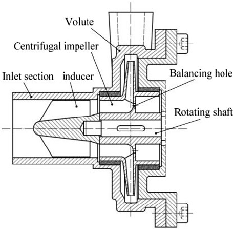
FIGURE 5. Pressure and gas phase distribution diagrams of the pump before and after designing the hole (Hao Gao, 2020).
The specific area of the balance hole is an important factor that affects the anti-cavitation ability of the pump. The larger the area of the balance hole, the larger is the leakage of the balance hole, and the vortex is induced at the inlet of the centrifugal impeller. Cheng (Xiaorui Cheng, 2020; Xiaorui Cheng, 2020) designed balance holes with different specific areas in pumps and analyzed the flow field. The simulated streamlines in Figure 6 show that flow in the balance hole is smooth when the specific area of the balance hole K = 0.5 and K = 1.
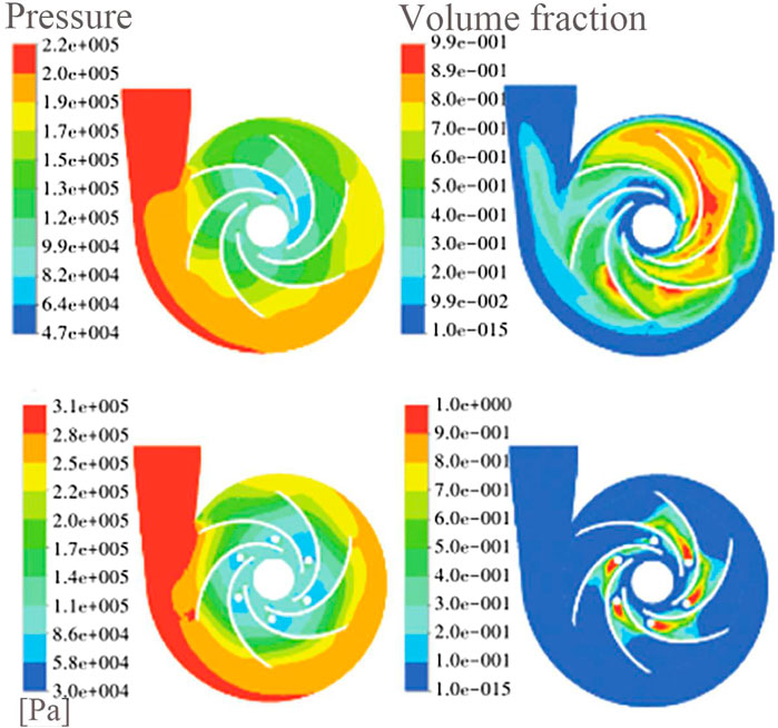
FIGURE 6. Axial flow field distribution of the high-speed centrifugal pump with different balance hole-specific areas (Xiaorui Cheng, 2020).
Hydraulic Excitation
The second problem is hydraulic excitation. The excitation force is affected by the backflow and vortex. The research on the backflow and vortex has been provided in Cavitation. In addition, cavitation also has a great impact on it. Yeqiang Li (2017) simulated the distribution of the root-mean-square, as shown in Figure 7. Through comparison, it was found that the interaction becomes stronger in amplitude when cavitation occurs.
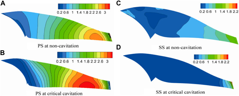
FIGURE 7. Prms on PS and SS of the blade (Yeqiang Li, 2017). (A) PS at non-cavitation. (B) PS at critical cavitation. (C) SS at non-cavitation. (D) SS at critical cavitation.
For the excitation force, Wei Dou (2013) proposed that the main exciting force of the impeller can be divided into constant force and pulse force, while the interference between the impeller and tongue generates the variable excitation force. Qiaorui Si (2020) found that the pressure fluctuation nearby the tongue position might cause the radiated noise.
Orifice Plate Design
The orifice plate is used to block the axial velocity of the backflow, which can suppress the backflow vortex. The main factors that affect the backflow are the orifice diameter, orifice thickness, orifice shape, and orifice position.
Xiaomei Guo (2011) simulated nine different schemes of the orifice plate design by the orthogonal method. It is concluded that the diameter of the orifice plate is the main factor affecting backflow, the thickness of the orifice plate is the second, and the distance between the orifice plate and the leading edge of the inducer is the third. Wenwu Song (2017) installed different kinds of orifice plates in the inlet section of the pump. It can be seen from Figure 8 that the backflow vortices are reduced after the orifice plate is installed, and the number of vortices in the C-type orifice plate is less.
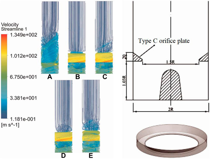
FIGURE 8. Streamlines of different orifice plates and c-type orifice plate structures: (A) without orifice plate, (B) type A orifice plate, (C) type B orifice plate, (D) type C orifice plate, and (E) type D orifice plate (Wenwu Song, 2017).
In order to study the influence of the diameter of the c-type orifice plate, Chengfan Shi (2019) installed different diameters of the c-type orifice plate in the pump. It can be seen from Figure 9 that there is no axial backflow when the aperture is 1.0 and 0.8 R.
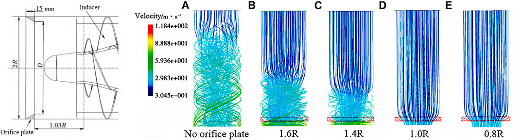
FIGURE 9. Structure of the orifice plate and streamline distribution of the inlet section (Chengfan Shi, 2019). (A) Without orifice plate. (B) D = 1.6R. (C) D = 1.4R. (D) D = 1.0R. (E) D = 0.8R.
For other types of orifice plates, Wenwu Song (2020) studied the effect of inclination angles of orifice plates on the backflow. As shown in Figure 10, the comparison shows that there are no vortices in the mainstream at 10°/0° and 20°/20°. It is pointed out that the suppression effect of the backflow vortex is obviously better when the angle is negative.
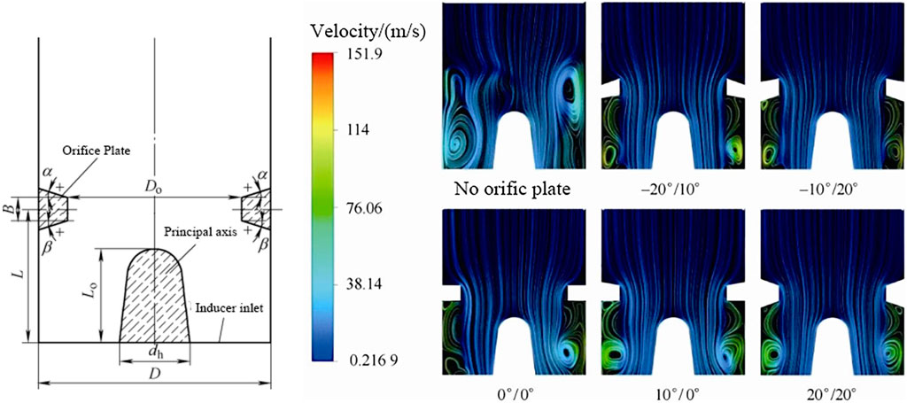
FIGURE 10. Orifice plate structure and sketch of the axial section (Song Wenwu, 2020).
Impeller Design
The structure of the impeller has a great influence on the pump. The inlet shape of the blade can change the flow condition and outlet velocity in the impeller. Qiang Li (2019) found that the highest amplitude of pressure pulsation is at the tongue. Also, it is pointed out that the vibration is caused by the interaction between the volute and the tongue. The pressure pulsation is affected by the splitter blades. Jun Liu (2013) designed three types of splitter blades and observed the flow field. From the results, the cross-section static pressure displays better uniformity in the impeller with splitter blades. Yuan Ye (2019) replaced the original impellers with two new types of impellers with splitter blades. The result shows that the pulsating pressure of the original scheme (Scheme 1) is obviously higher than the others.
Guide Vane Design
The guide vane is located between the impeller outlet and the volute. It is found that the guide vanes can change the interference between the impeller and the volute. Therefore, hydraulic excitation can be reduced by guide vanes’ design (Xiuxin Yang, 2017).
The vortex in the guide vane channel is related to the relative position between the impeller and the guide vane. From Baofeng Yang’s (2019) study, the vortex in the flow of different guide vanes and impellers is quite different. The number of guide vanes and impeller blades can affect hydraulic excitation. Rong Xue (2019) did research on the effects of the number of impeller blades and guide vanes on the pumps. It can be seen from Figure 11 that the vortex is related to the number of guide vane and impeller blades.
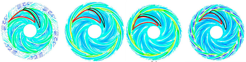
FIGURE 11. Velocity streamline of the high-speed pump under four computational cases (Rong Xue, 2019).
Inefficient Problem
The pump’s specific speed will have a great impact on the efficiency. A high-speed centrifugal pump with a specific speed of less than 80 is called an ultra-low specific speed high-speed centrifugal pump, which has the characteristics of low efficiency. To solve the problem of low efficiency, four methods are proposed, which are the enlarged flow rate design method, area ratio method, no-overload design method, and complex impeller design method (Junhu Yang, 2006; Zuchao Zhu, 2007; Yang Wang, 2012; Zhongqiang Ma, 2015; Qiang, 2017). The most widely used method earlier is the enlarged flow rate design method and splitter blade design.
Enlarged Flow Rate Design Method
The enlarged flow rate design method is to design the pump with enlarged parameters, which is the most direct and effective way to improve efficiency. It is expressed as a formula as follows:
In order to obtain the most accurate amplification factor, Junhu Yang (2005) introduced the equation in the general expression of the enlarged flow rate design method:
According to the dimensionless efficiency curve, Yongyan Ni (2008b) pointed out that the efficiency would decrease in the small flow region. The only flow amplification coefficient is obtained according to the equation.
Protopopov A (2019) proposed a multi-index optimization method for the low flow rate. The appropriate value can be found through the head and cavitation of these points.
It is necessary to make changes to the structure such as the inducer and impeller in the design of the enlarged flow rate design method. Generally, the exit position angle
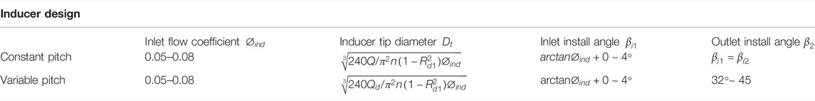
TABLE 1. Inducer design.
Complex Impeller Design Method
This method is based on the idea of changing the internal flow field of the impeller, using the splitter blade to scour the wake, which can effectively prevent the further development of the wake (Baolin Cui, 2007; Heng, 2019).
The splitter blades have been widely used in the design of ultra-low specific speed high-speed centrifugal pumps. Xueyi Qi (2009b; a) pointed out that the order of precedence affecting the efficiency is the number of short blades, the relative position of the radial inlet, the circumferential offset, and the deflection angle. As shown in Figure 12, the splitter blade can improve the efficiency of the pump, and the effect is better at a large flow rate. The method of the splitter blade structure is obtained by adjusting the value of the long blade space cylindrical coordinate points.
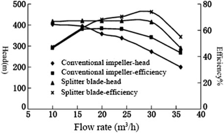
FIGURE 12. Performance curve of the head and efficiency (Xueyi Qi, 2009b).
Structural Design of the High-Speed Centrifugal Pump
The structure of a high-speed centrifugal pump plays a key role in the operation of the pump. The key to realizing the high head is motor power and speed. With the increased demand for industrial production, the head is higher and higher, the power is bound to become higher, the structure will be more compact, and the material will be more outstanding. In order to ensure the stability of the pump, the structure needs to be reasonably designed.
Gearbox Design
The gearbox is widely used in a high-speed centrifugal pump. The impeller obtains high speed by the gearbox. There are two kinds of gears in the gearbox: the single step gear and double step gear. The single step gear is based on the gear tooth ratio for the speed-up process. The double step gear drives with an intermediate shaft in the middle.
In the gear design, the small modulus involute spur gear is used to reduce wear. Compared with the helical gear, it has the characteristics of small vibration, low noise, and long life. B Guilbert (2019) found that both thin-rimmed gear geometry and operating conditions must be accounted for. Moreover, it is very important to study the influence of vibration. The vibration will cause a greater impact on the gear (Zhongxu Cui, 2020). Min Yang (2016) pointed out that there are swing, torsional vibrations, and bending in the vibration mode of the gearbox. Anmin Zhou (2021) pointed out that the frequency response in two directions was composed of the fp component, fg component, fm component, and 2fm component. It is found that there is an obvious jumping phenomenon in the x direction when the transmission ratio is 1.25.
Bearing Design
Hydraulic excitation, cavitation, wear structure defects, the fault of the lubricating oil system, and other problems will have a certain impact on the bearing, which may cause a bearing problem, such as abnormal bearing temperature, or bearing fracture. The research on the bearing is of great significance to the design of the pump.
There are many types of bearing. Jie Zhou (2015) compared polymer-lined thrust bearings with babbitt-lined bearings. It is pointed out that the thrust bearing is better in terms of load-bearing. Hongping Zhou (2015) obtained the temperature distribution of the ceramic ball bearing, which lays the foundation for the further study of bearing. Rong Xue (2019) presented a new type of hydrodynamic bearing using working fluid as a lubricant, as shown in Figure 13.
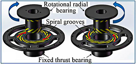
FIGURE 13. Details of hydrodynamic bearings (Rong Xue, 2019).
Bearing is affected by the unbalanced force. The analysis of Y X Bai (2016) shows that the capacity, maximum deformation, and pressure of water film are consistent with the increasing trend in radial clearance. It is pointed out that a reasonable selection of radial clearance is the key to improving the bearing performance.
Sealing Design
The sealing system is very important for the whole system. As the speed of the impeller increases, its requirements for sealing performance become higher. The mechanical seal is one of the key parts of the pump. Through its reasonable design, the leakage, vibration, and lubrication problems of the pump can be solved.
In terms of the sealing design, Sundyne’s high-speed centrifugal pump is superior in sealing performance. It has three types of seals: the single seal, double seal, and tandem seal. Three kinds of sealing methods are used in different occasions to ensure the stable operation of the pump (2011). Through research, it is found that there are a number of factors that can affect the seal. Xudong Peng (2019) pointed out that the rotating speed, medium pressure, and circulation of the sealing medium all affect the temperature of the sealing bearing end face. Yancheng Yu (2014) pointed out that the leakage of the mechanical seal was caused by the bad following performance of the high-speed mechanical seal and the failure of the auxiliary seal ring.
Motor Design
The motor can provide power for the whole system, which is the basis of realizing the function of the pump. The gearbox is complex, expensive, and difficult to maintain. Thus, new methods are proposed to achieve high speed, such as the high-speed permanent magnet synchronous motor (HPSM). The HPSM is more efficient in performance. In addition, the volume of the system is also smaller than the general use of the gearbox, which can achieve high efficiency (Gang-Hyeon Jang, 2018). In the HPSM study, Simon M. Barrans (2017) presented a model that considers both the radial and axial interactions between the magnet and the jacket during design interference. Wan Yuan (2017) established a stress analysis model for a brushless electric motor rotor under high centrifugal force, rotor heating, and accelerated impact, which can provide a reference for the rotor design. Gang-Hyeon Jang (2018) designed a high-speed brushless electric motor for high-speed centrifugal pumps, as shown in Figure 14.
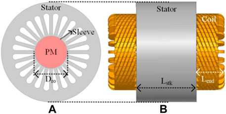
FIGURE 14. Structure of a high-speed PMSM. (A) 2D model. (B) 3D shape of the PMSM model (Gang-Hyeon Jang, 2018).
Vibration Monitoring System
Pump failure is inevitable in operation. There are four types of failures in a high-speed centrifugal pump, which are the motor problem, seal problem, lubrication problem, and abnormal vibration. The motor overload problem is a widely seen motor failure, which is caused by the motor itself, the gearbox, or the stuck shaft. The cause of the seal problem is that the particles are mixed into the sealing cavity, the sealing parts are worn, or the sealing surfaces of the moving and static rings are not uniform. Oil seal leakage, excessive oil consumption, abnormal oil temperature, or bearing gear wear will lead to lubrication failure. The reason for vibration can be summarized as the following two parts: one is the vibration caused by hydraulic excitation. The other is caused by mechanical factors, such as unreasonable design, large assembly clearance, and rotor mass unbalance. In addition, the aforementioned problems will also cause vibration.
Pump vibration is affected by many factors. Research studies show that the failure of the pump is closely related to its vibration. Also, it is found that the research on vibration data can indeed be used to diagnose the early faults. In the study of vibration, Miloš Milovančević (2018) analyzed the vibration of the pumping aggregate and made a comparative study of three different soft computing methods. By setting the vibration monitoring at the same position of the bearing, according to the vibration frequency analysis, the possible cause of the faults can be obtained (Ni Yongyan, 2008a).
Conclusion
This article highlights the research on the designs and issues of high-speed centrifugal pumps, including the hydraulic problem such as cavitation, hydraulic excitation, inefficiency, and their solution, and the current state of the gearbox, bearing, seal, and motor. All of them are critical to the pump design and application. The following ideas will be of great help to the further development of the pump.
1) The biggest challenges for high-speed centrifugal pumps are cavitation and hydraulic excitation. There is a mutual influence between cavitation and hydraulic excitation, which should be taken into account when conducting research on each of them.
2) The enlarged flow rate design method, area ratio method, no-overload design method, and complex impeller design method can be used to solve the low-efficiency issue at an ultra-low specific speed. A combination of these methods can be considered to further improve efficiency.
3) Combining the new structural design with the pump design can improve the practicability of the pump. The innovation of speed-increasing methods, seal structure, bearing structure, and motor can solve the structural problems.
4) The material of the pump has a great impact on the performance and life of the pump. The improvement of the pump will require higher properties of the material. The application of new materials can greatly improve the design of the pump.
5) The rapid and accurate diagnosis of pump failure is of great significance to industrial production. The on-line monitoring of pump failure can improve the practicability of the pump and make the system more intelligent. The failure analysis and classification are of great significance to the establishment of the on-line monitoring system.
Author Contributions
Conceptualization: SX. Supervision: JH, LW, and MG. Funding acquisition: ZZ, DQ, GP. Writing—original draft: YH.
Funding
This work was supported by the Top-notch Talent Support Program of Zhejiang Province (2019R51002), the NSFC program (No. 52071296), the Key Research and Development Program of Zhejiang Province (Nos. 2020C01027 and 2020C03099).
Conflict of Interest
The authors declare that the research was conducted in the absence of any commercial or financial relationships that could be construed as a potential conflict of interest.
Publisher’s Note
All claims expressed in this article are solely those of the authors and do not necessarily represent those of their affiliated organizations, or those of the publisher, the editors, and the reviewers. Any product that may be evaluated in this article, or claim that may be made by its manufacturer, is not guaranteed or endorsed by the publisher.
References
Anmin Zhou, L. Z., Zhu, Z., Guo, J., Zhang, X., and Cui, B. (2021). Effects of Transmission Ratio on the Nonlinear Vibration Characteristics of a Gear-Driven High-Speed Centrifugal Pump. Shock Vib. 2021, 1–15. doi:10.1155/2021/6629241
Bai, Y. X., Kong, F. Y., Sun, J. R., and Yuan, X. (2016). Study on Water Lubricated Bearings of High Speed Pump Based on Numerical Simulation. IOP Conf. Ser. Mater. Sci. Eng. 129. doi:10.1088/1757-899X/129/1/012031
Baofeng Yang, B. L., Chen, H., and Liu, Z. (2019). Entropy Production Analysis for the Clocking Effect between Inducer and Impeller in a High-Speed Centrifugal Pump. Proc. Institution Mech. Eng. Part C J. Mech. Eng. Sci. 233 (15), 5302–5315. doi:10.1177/0954406219843946
Berten, S., Dupont, P., Fabre, L., Kayal, M., Avellan, F., and Farhat, M. (2009). .Experimental Investigation of Flow Instabilities and Rotating Stall in a High-Energy Centrifugal Pump Stage, in Proceedings of ASME 2009 Fluids Engineering Division Summer Meeting. Volume 1: Symposia, Parts A, B and C, Vail, Colorado, August 2–6, 2009, 505–513. doi:10.1115/FEDSM2009-78562
Cheng Xiaorui, C. Z. (2020). Effect of Balancing Hole Specific Area on Performance of High Speed Centrifugal Pump. Fluid Mach. 48 (6), 31–37+19. doi:10.3969/j.issn.1005-0329.2020.06.006
Cui Baolin, Z. Z., and Li, Y. (2007). "The Flow Simulation in Three Type High-Speed Centrifugal Pump Impeller" in Proceedings of ISFP"2007:5th International Symposium on Fluid Power Transmission and Control, Beidaihe, China, June 6–8, 2007.
Cui Zhongxu, H. K., Yue, Yu., Liu, Y., Zhang, H., Liu, D., Zheng, D., et al. (2020). Failure Analysis and Treatment of the Damage of High-Speed Pump Gear. Pretrochemical Equip. Technol. 41(06), 37-40±36-37. doi:10.3969/j.issn.1006-8805.2020.06.008
Debarpan Paul, H. A., and Rao Ponangi, B. (2020). CFD Analysis of Two-phase Cavitating Flow in a Centrifugal Pump with an Inducer. Heat. Transf. 49 (6), 3854–3881. doi:10.1002/htj.21812
Dou Wei, L. Z. (2013). Effect of the Hydrodynamic Forces on the Vibration of Rotor in a Centrifugal Pump. Mech. Sci. Technol. Aerosp. Eng. 32 (03), 377–382. doi:10.13433/j.cnki.1003-8728.2013.03.017
Gang-Hyeon Jang, J.-H. A., Kim, B-O., Dong-Hyun Lee, J-S. B., and Choi, J-Y. (2018). Design and Characteristic Analysis of a High-Speed Permanent Magnet Synchronous Motor Considering the Mechanical Structure for High-Speed and High-Head Centrifugal Pumps. IEEE Trans. Magnetics 54 (11), 1–6. doi:10.1109/tmag.2018.2845874
Gao Hao, W. Y. (2020). Effect of Hole - Opening Impeller on High - Speed Centrifugal Pump under Gas - Liquid Two - Phase Condition. J. Wuhan Inst. Technol. 42 (6), 683–687. doi:10.19843/j.cnki.CN42-1779/TQ.202008018
Guilbert, B., Velux, P., and Cutuli, P. (2019). Quasi-static and Dynamic Analyses of Thin-Webbed High-Speed Gears: Centrifugal Effect Influence. Proc. Institution Mech. Eng. Part C J. Mech. Eng. Sci. 233 (21-22), 7282–7291. doi:10.1177/0954406219855411
Guo Xiaomei, Z. Z., Cui, B., and Yi, Li. (2012). Inducer-Short Blade Position Influence on Cavitation Performance of High Speed Centrifugal Pump. J. Eng. Thermophys. 33 (10), 1695–1698.
Guo Xiaomei, Z. Z., Cui, B., and Yi, Li. (2011). Study of Pre-positioned Orifice’s Parameters before the Inducer Based on Orthogonal Test. J. Eng. Thermophys. 32 (08), 1319–1322.
Guohong, W. (2016). in Performance Analysis of Cavitating Flow in High-Speed Centrifugal Pump with Semi-open Impeller. Editor L. U. O. Technology (Lanzhou, China: Lanzhou University of Technology).
Heng, W. (2019). in Effect of Splitter Blade Geometric Parameters on Hydraulic Performance of Low Specific Speed Centrifugal Pump. Editor L. U. O. Technology. (Lanzhou, China: Lanzhou University of Technology).
Hu Shuai, S. W., Hui, P., and Lichao, W. (2017). Numerical Analysis of Cavitation Characteristics of High-Speed Micro-pump at Small Flow Rate. J. Of Eng. For Therm. Energy And Power 32 (8), 100–106+151. doi:10.16146/j.cnki.rndlgc.2017.08.0016
Huang Xilong, C. W., Wang, W., Yan, J., and Xu, K. (2020). Performance of High-Speed Centrifugal Pump with Different Pre-positioned Inducer. J. Rocket Propuls. 46 (2), 64–70.
Jianping Yuan, Y. Z., and Ge, A. (2014). A CFD Study on Cavitating Flow in High-Speed Centrifugal Pumps under Low Flow Rates. Adv. Mater. Res. 945-949, 914–923. doi:10.4028/www.scientific.net/AMR.945-949.914
Jie Zhou, B. B., Argires, J., and Pitsch, D. (2015). Experimental Performance Study of a High Speed Oil Lubricated Polymer Thrust Bearing. Lubricants 3 (1), 3–13. doi:10.3390/lubricants3010003
Jin Jiang, Y.-h. L., Pei, C-y., Li, L-l., Fu, Y., Cheng, H-G., and Sun, Q-Q. (2019). Cavitation Performance of High-Speed Centrifugal Pump with Annular Jet and Inducer at Different Temperatures and Void Fractions. J. Hydrodynamics 31 (1), 93–101. doi:10.1007/s42241-019-0011-7
Jun Liu, J. Y., and Zhang, W. (2013). Fluid Mechanics Analysis and Effect of Splitter Blades on the Characteristics of High-Speed Centrifugal Pump. Adv. Mater. Res. 676, 124–129. doi:10.4028/www.scientific.net/AMR.676.124
Kraeva, E. M. (2010). Calculation of Energy Parameters in High-Speed Centrifugal Pumps of Low Specific Speed. Aircr. Rocket Engine Theory 53, 73–76. doi:10.3103/S1068799810010125
Li Huimin, L. X., Jiang, J., and Zhang, D. (2020). Influence of Outlet Parameters of Inducer on Performance of High Speed Centrifugal Pump. J. Rocket Propuls. 46 (01), 69–75.
Li Huimin, W. X., Zhao, R., and Hui, C. (2019). Cavitation Oscillations and It's Control of High-Speed Centrifugal Pump. Missiles Space Veh. 4 (02), 44–48. doi:10.7654/j.issn.1004-7182.20190210
Li Qiang, L. S., Yan, H., Wang, D., and Xia, S. (2019). Influence of Blade Leading Edge Shape on Performance of Micro-high-speed Centrifugal Pump. J. drainage irrigation Mach. Eng. 37 (7), 587–592. doi:10.3969/j.issn.1674-8530.17.0192
Li Yeqiang, Y. S., and Lai, H. (2017). Numerical Study of Unsteady Flows with Cavitation in a High-Speed Micro Centrifugal Pump. J. Therm. Sci. 26 (1), 18–24. doi:10.1007/s11630-017-0904-0
Lihong, Z. (2016). in Study of Internal Flow in High-Speed Centrifugal Pump with Semi-open Impeller. Editor L. U. O. Technology (Lanzhou, China: Lanzhou University of Technology).
Luo Xu, S. W., Yu, J., Wan, L., and Chen, J. (2018). Research on Multidimensional Cavitation Characteristics of High-Speed Centrifugal Pumps. Water Power 44 (6), 71–74+115.
Ma Zhongqiang, Z. S., Ma, Yi., Deng, H., Zhang, Z., and Zhang, H. (2015). Non-overload Optimization Design of Medium Specific Speed Pump Based on Orthogonal Design Method. Fluid Mach. 43 (10), 42–46+83. doi:10.3969/j.issn.1005-0329.2015.10.009
Miloš Milovančević, V. N., Petkovic, D., Vracar, L., Emil, V., Tomic, N., and Jović, S. (2018). Vibration Analyzing in Horizontal Pumping Aggregate by Soft Computing. Measurement 125 (2018), 454–462. doi:10.1016/j.measurement.2018.04.100
Ni Yongyan, Y. S., Pan, Z., and Yuan, J. (2008a). Detection of Cavitation in Centrifugal Pump by Vibration Methods. Chin. J. Mech. Eng. 21 (5), 46–49. doi:10.3901/CJME.2008.05.046
Ni Yongyan, Y. S., Yuan, J., and Pan, Z. (2008b). Model of Enlarged Flow Design for Low-specific Speed Centrifugal Pump. Drainage Irrigation Mach. 26 (01), 21–24.
Peng, X., Jin, J., Ding, L., Jiang, J., Meng, X., and Li, J. (2019). Analysis of Face Temperature in Mechanical Seal Applied in the High Speed Turbo Pump. Tribology 39 (3), 313–318. doi:10.16078/j.tribology.2018095
Protopopov A, V. V. (2019). Development of Methods for High-Speed Centrifugal Pump Analysis. IOP Conf. Ser. Mater. Sci. Eng. 492. doi:10.1088/1757-899x/492/1/012003
Qi Xueyi, H. J., Chen, D., Xia, G., and Kong, Y. (2009a). Geometric Formation Method of Short Blades on Compound Impeller of High-Speed Centrifugal Pump with Super-low Specific Speed. J. Lanzhou Univ. Technol. 35 (6), 41–45. doi:10.13295/j.cnki.jlut.2009.06.025
Qi Xueyi, H. J., and Tian, Y. (2009b). Orthogonal Design of Complex Impeller of Centrifugal Pump with Super-low-specific-speed. Drainage Irrigation Mach. 27 (06), 341–346.
Qiang, Z. (2017). in Hydraulic Design and Numerical Simulation of High-Speed Centrifugal Pump with Ultra-low Specific Speed. Editor Y. University (Yangzhou, China: Yangzhou University).
Qiaorui Si, C. S., He, X., Li, H., Huang, K., and Yuan, J. (2020). Numerical and Experimental Study on the Flow-Induced Noise Characteristics of High-Speed Centrifugal Pumps. Appl. Sci. 10 (9), 1–22. doi:10.3390/app10093105
Rong Xue, Y. C., Fang, X., Chen, L., and Hou, Y. (2019). Optimization Study on a Novel High-Speed Oil-free Centrifugal Water Pump with Hydrodynamic Bearings. Appl. Sci. 9 (15), 3050. doi:10.3390/app9153050
Shi Chengfan, S. W., Li, J., and Wan, L. (2019). Influence of Slope Orifice Diameter on Flow Characteristics of Centrifugal Pump with Inducer. J. Of Eng. For Therm. Energy And Power 34 (5), 37–41+148. doi:10.16146/j.cnki.rndlgc.2019.05.006
Simon, M., Barrans, M. M. J. A.-A., and Carter, J. (2017). Mechanical Design of Rotors for Permanent Magnet High-Speed Electric Motors for Turbocharger Applications. IET Electr. Syst. Transp. 7 (4), 278–286. doi:10.1049/iet-est.2016.0081
Song Wenwu, S. J., Lichao, W., Hu, S., Xu, L., and Chen, J. (2020). Analysis of Backflow Vortex and Cavitation of High Speed Centrifugal Pump. J. Mech. Eng. 56 (4), 95–103. doi:10.3901/jme.2020.04.095
Songsheng Deng, G. L., Guan, J., Chen, X., and Liu, L. (2019). Numerical Study of Cavitation in Centrifugal Pump Conveying Different Liquid Materials. Results Phys. 12, 1834–1839. doi:10.1016/j.rinp.2019.02.009
Sundyne Pumps Brochure (2011) "Sundyne Pumps Brochure". Available at: https://www.sundyne.com/products/sunflo-industrial-grade-pumps/p-3400-pump/#downloads).
Wang Yang, L. J., and He, W. (2012). Parameter Optimization of Non-overload Centrifugal Pump. Trans. CSAE 28 (3), 33–37. doi:10.3969/j.issn.1002-6819.2012.03.006
Wenwu, S., Lichao, W., Jie, F., Jianwei, S., Xiuxin, Y., and Qianyu, X. (2017). Analysis and Control of Flow at Suction Connection in High-Speed Centrifugal Pump. Adv. Mech. Eng. 9 (1), 1–12. doi:10.1177/1687814016685293
Xiaorui Cheng, Z. C., and Jiang, Y. (2020). Study on the Influence of the Specific Area of Balance Hole on Cavitation Performance of High- Speed Centrifugal Pump. J. Mech. Sci. Technol. 34 (8), 3325–3334. doi:10.1007/s12206-020-0725-z
Yancheng, Y. (2014). The Improvement of Sealing System of Vertical High-Speed Pump. Guangzhou Chem. Ind. 42 (13), 149–151.
Yang Junhu, Z. R. (2005). A Method for Calculating the Enlarge Coefficient of Low Specific Speed Centrifugal Pump. Chin. J. Mech. Eng. 41 (4), 203–205.
Yang Junhu, Z. R., Wang, C., Ma, J., and Wang, X. (2006). Area-ratio Principle for Centrifugal Pumps with Low Specific-Speed. J. Lanzhou Univ. Technol. 32 (5), 53–55.
Yang Min, D. Y., Dai, K., and Ma, G. (2016). Modal Analysis of Gear Box of High Speed Pump. Process Equip. Pip. 53 (4), 55–58+63.
Yang Xiuxin, S. W., Lichao, W., and Shi, J. (2017). Influence of Radial Guide Vane on Unsteady Flow of High-Speed Centrifugal Pump. J. Of Eng. For Therm. Energy And Power 32 (4), 93–98+141. doi:10.16146/j.cnki.rndlgc.2017.04.014
Ye Yuan, S. Y., and Tang, L. (2019). Investigation on the Effect of Complex Impeller on Vibration Characteristics for a High-Speed Centrifugal Pump. Proc. Institution Mech. Eng. Part A J. Power Energy 234 (5), 611–624. doi:10.1177/0957650919878313
Yuan Wan, S. C., Wu, S., Member, I. E. E. E., Song, L., Milyaev, I. M., and Yuryevich, S. O. (2017). Shock-Resistance Rotor Design of A High-Speed PMSM for Integrated Pulsed Power System. IEEE Trans. Plasma Sci. 45 (7), 1–7. doi:10.1109/TPS.2017.2705347
Zhao, J. L., Wang, H. J, Gong, R. Z., Xuan, T., and Li, X. Y. (2014). “Vortex Structure Research Method Based on Q-Criterion in a High-Speed Centrifugal Pump,” in ISFMFE - 6th International Symposium on Fluid Machinery and Fluid Engineering, 1–6. doi:10.1049/cp.2014.1160
Zhou Hongping, X. B., Ding, Z., and Fu, K. (2015). Bearing Temperature Field Analysis of High Speed Small Composite Molecular Pump. J. Southwest Univ. Sci. Technol. 30 (2), 97–100.
Keywords: high-speed centrifugal pump, cavitation, hydraulic excitation, ultra-low specific speed, structural design
Citation: Hao Y, Hao J, Zuchao Z, Xianghui S, Wenqi L, Gruszczynski M, Qiangmin D and Panlong G (2022) Review of the Hydraulic and Structural Design of High-Speed Centrifugal Pumps. Front. Energy Res. 10:899093. doi: 10.3389/fenrg.2022.899093
Received: 18 March 2022; Accepted: 16 May 2022;
Published: 24 June 2022.
Edited by:
Angelo Maiorino, University of Salerno, ItalyCopyright © 2022 Hao, Hao, Zuchao, Xianghui, Wenqi, Gruszczynski, Qiangmin and Panlong. This is an open-access article distributed under the terms of the Creative Commons Attribution License (CC BY). The use, distribution or reproduction in other forums is permitted, provided the original author(s) and the copyright owner(s) are credited and that the original publication in this journal is cited, in accordance with accepted academic practice. No use, distribution or reproduction is permitted which does not comply with these terms.
*Correspondence: Su Xianghui, c3V4aWFuZ2h1aUB6c3R1LmVkdS5jbg==