 Syed Muhammad Amrr 1*
 Javed Ahmad 2
 Sofi Abdul Waheed 3
 Adil Sarwar 4
 Abdelaziz Salah Saidi 5,6
 M. Nabi 1
- 1Department of Electrical Engineering, Indian Institute of Technology Delhi, New Delhi, India
- 2Department of Electrical Engineering, National Taiwan University of Science and Technology, Taipei, Taiwan
- 3Department of Electrical Engineering, National Institute of Technology Srinagar, Jammu & Kashmir, India
- 4Department of Electrical Engineering, Aligarh Muslim University, Aligarh, India
- 5Department of Electrical Engineering, King Khalid University, Abha, Saudi Arabia
- 6Laboratoire des Systèmes Electriques, Ecole Nationale d’Ingénieurs de Tunis, Université de Tunis El Manar, Tunis, Tunisie
This paper investigates the use of a new sliding mode control for the output voltage regulation of boost converter under parametric uncertainties of load resistance and input voltage. Owing to the fact that the proposed scheme employs the adaptation law; therefore, apriori knowledge about the upper bound value of uncertainties is not required while selecting the controller gains. Moreover, the stability analysis of the closed-loop system guarantees the finite-time convergence of output voltage to the desired value while ensuring robustness against uncertainties. The numerical simulation and hardware analysis illustrate the effective performance of the developed strategy.
1 Introduction
The last two decades have seen significant growth in the integration of renewable energy sources (RES) into the power grid to expand the worldwide penetration of such energy sources. The RES are used as alternative energy sources in the localized grid, known as microgrids, that can be detached from the main grid when required. With the use of power converters, these microgrids can take the form of AC and/or DC microgrids (Amrr et al., 2018; Amrr et al., 2021; Singh et al., 2021; Muktiadji et al., 2022). Clean energy, such as fuel cells, photovoltaic energy, wind, and so on, are summarily endorsed in microgrids to safeguard the Earth (Saidi, 2022). However, the electrical features of unpolluted energy are unsympathetically affected by environmental and load changes (ImdadullahAmrr et al., 2021). For this reason, a dc-dc converter is essential to provide a stable output voltage at the output stage of clean energy.
DC-DC converters (buck type, boost type, and buck/boost type) are widely utilized in industrial applications for power conversion, including uninterruptible electrical power, dc motor drives, power systems, hybrid electric cars, medical equipment, telecommunications, portable recharging devices etc. However, it is crucial to mention that the output voltage requirement varies with different application situations (Leon et al., 2017; Hernández-Márquez et al., 2018; Muktiadji et al., 2022). Some applications, for example, need the converter output to have a quick dynamic response and a low voltage ripple. Moreover, some application demands a constant output voltage while experiencing parameter uncertainties and load changes. Therefore, industries and academics have been focusing on developing the most effective and efficient control approach for eachapplication in recent decades (Tan et al., 2005; Park and Cho, 2014; Hernández-Márquez et al., 2019; Yin et al., 2020).
The DC microgrid incorporates a DC-DC boost converter to connect the DC bus and the DC energy source, such as photovoltaic array, fuel cell, and battery (Balog et al., 2012). The DC-DC boost converter is usually employed to boost up the DC voltage to a higher level, i.e., the output voltage is greater than its input supply. Further, it is frequently used at the primary stage in a clean power system to generate more controlled DC voltage for later usage of the inverter. The mathematical model of a DC-DC boost converter is a nonlinear variable structured (Nizami and Chakravarty, 2020), has a nonminimum phase (Tahri et al., 2019), and time-varying behavior (Zhang et al., 2017). The controller design for duty cycle generation of the converter is challenging because of disturbances caused by load changes, input voltage fluctuation, and electromagnetic interference rendered by the semiconductor switching operation (Liu et al., 2018). Furthermore, adjusting the output voltage requires continuous inductor current information (Bouchekara et al., 2021). Consequently, an additional current sensor is needed (Shen et al., 2021). Therefore, the boost converter requires a high-performing control system that can provide effective disturbance rejection, low steady-state error, minimal overshoot, rapid recovery time, and fast transient reaction time to achieve a good system response.
In the past, various control strategies have been developed for controlling the output voltage of boost converters, including proportional-integral (PI), proportional-integral-derivative (PID), neural network, fuzzy control, backstepping technique, sliding mode control (SMC), etc (Guo et al., 2011; Nizami and Chakravarty, 2020; Guo and Abdul, 2021; Muktiadji et al., 2022). In general, PID-type or PI-type control systems are popular due to their simpler structure, ease of design, and low price. Guo et al. (2011) use a DSP-based controller to regulate the boost converter voltage with PI and PID designs. The findings show that PID and PI controllers are sluggish to acquire a transient response, have a significant overshoot at starting, are less stable, and are less resilient to operating point changes. The design principle of PID or PI is based on the linearization of controller system to construct its performance in the frequency domain (Mummadi, 2011). These controllers are not suitable for large-signal disturbances, such as suddenly large load changes to the system based on this constraint (Khan and Sundareswaran, 2014). Moreover, when there are system uncertainties, the stability of such control systems cannot be guaranteed, and control gains need to be repeatedly tuned to ensure favourable performance. The disturbance rejection problem for a non-minimum phase DC-DC boost converter is investigated in (Kobaku et al., 2021) using a robust PID controller. However, the drawback of PID controller is that it requires linearization to acquire a control parameter for a specific operating point. As a result, the boost converter cannot operate in all situations and operating ranges.
On the other hand, the sliding mode control (SMC) or variable structure control is a well known robust nonlinear control strategy. The SMC has a fast control action, better transient and steady state performances, and invariant against matched uncertainties and disturbances when the system dynamics are in sliding phase (Utkin, 1977; Saha et al., 2019; Amrr and Alturki, 2021; Wei et al., 2021). However, there are some problems associated with SMC, like chattering phenomena, inconstant frequency of switching, which can create excessive wear and tear on power switches, increased heat losses in the power circuit, and electromagnetic interference (EMI) problems (Utkin et al., 2020). The SMC has been researched to develop adjustment feedback structures for SMC based on hysteresis control in order to resolve chattering phenomena and switching frequency of higher order (Tan et al., 2006). By properly regulating the hysteresis band and sliding factor, the SMC based on the hysteresis modulation scheme becomes stronger against changes in input voltage and output charge. However, the frequency of switching cannot be guaranteed to be constant (Tan et al., 2006). In (Tan et al., 2007), an equivalent control-based SMC is developed to try and resolve the chattering phenomena problem and the non-constant frequency of switching. Unfortunately, in these investigations, equivalent control signals are unable to address possible system uncertainties. Martínez-Treviño et al. (2017) reported an SMC-based scheme for a boost converter to deliver a constant power demand. However, the system response has a significant chattering effect due to on-off type control design. A terminal SMC strategy is proposed in (Wang et al., 2016), however the finite-time convergence is not shown in the stability analysis. In (Wang et al., 2020), a composite control using disturbance observer (DO) and nonsingular terminal SMC is proposed to achieve a better transient response with improved robustness. However, it employs a coordinate transformation and DO approach, making the controller design relatively complex. Then, in (Yazici and Yaylaci, 2016), a fast terminal SMC is proposed for voltage tracking of DC-DC boost converter. Still there are few shortcomings in (Yazici and Yaylaci, 2016). First, parameters are tuned based on trial and error basis. Then, the upper bound of disturbance is assumed to be known apriori, which is not case in practical scenario. Lastly, finite time convergence is not shown in theory. Recently, a second order-based SMC scheme is proposed in (Cucuzzella et al., 2018) for designing a robust decentralized control for voltage regulation in boost-based DC microgrids. The second-order SMC approach produces continuous control inputs as duty cycles for the power converters. However, higher-order SMC is mathematically intensive and requires high computational power. In addition, the reaching phase of SMC is susceptible to the effects of disturbances. That means disturbance still influences the system dynamics in the reaching stage. To solve this issue, integral SMC is developed (Utkin and Shi, 1996) that guarantees the robustness from initial time t = 0.
In view of aforementioned literature, the proposed DC-DC boost converter control scheme employs an adaptive integral terminal SMC structure to achieve robustness against input and load variations. The combined integral and terminal sliding surface structure gives a better invariance throughout the operation. Also, it enables the finite-time convergence of the surface and the relative state. Further, the adaptive tuning of the controller gains helps in selecting control parameters, which further helps reduce chattering and control effort. The main contributions of this paper are as follows.
• The proposed regulation control provides the robustness against the input voltage fluctuation and load variations.
• Theoretically, it is proved that the developed scheme guarantees the finite-time convergence of output voltage to the reference value.
• Moreover, with the use of adaptive gains, the control design does not require apriori upper bound knowledge of uncertainties.
• The numerical simulations and hardware analyses validate the efficacy of the developed strategy.
2 Problem Formulation
The averaged mathematical dynamics of boost converter under continuous conduction mode with input and output uncertainties is expressed as Wai and Shih (2011).
where system state x1 is the average current flowing through inductor and state x2 denotes the average output voltage across the capacitor. The system parameters L, C, Rn, and Vin are the nominal inductor, capacitor, resistor, and input voltage, respectively. Further, ΔR and ΔVin denotes the variations in resistance and input voltage, respectively. The uncertainties in (1) can be clubbed together in a single term and can be rewritten as
where
Consider the course errors in the output voltage (ev) and inductor current (ei) as
where Vref and
With simple mathematical operations on (3) using (2) gives the error dynamical system as
where
2.1 Problem Statement
The aim of this brief is to develop a finite-time robust control scheme as duty cycle for the voltage regulation of boost converter under multiple uncertainties. In terms of mathematical expression, this can be described as:
where tf represents the finite-time.
In this brief, the following assumption and lemmas are used.
Assumption 1. The lumped uncertainty in the error dynamics (4) is considered to be bounded, but the knowledge of its upper bound is unknown, i.e., ‖Φ‖ ≤ ϖ, where ϖ > 0 is an unknown constant.
Lemma 1. (Yu et al., 2005). With γ ∈ (0, 2) and a vector
Lemma 2. (Bhat and Bernstein, 2000). Consider a Lyapunov function
then θ will converge to zero in finite-time with the settling time of
3 Proposed Controller and Stability Analysis
The proposed sliding surface
where α1 > 0 and α2 > 0 are the scalar constants,
The Proposed adaptive based terminal sliding mode control scheme is given as
where B+ is the left pseudo-inverse of B, i.e.,
where ϕ1 > 0 and ϕ2 > 0 decides the rate of adaptation and ϵ > 0 is significantly small design parameter.
3.1 Stability Analysis
Theorem 1. Consider the error dynamics of boost converter (4) under Assumption 1. The proposed control algorithm (8) will guarantee the convergence of sliding manifold (6) and system error to zero within finite-time.Proof. Closed-loop stability analysis of the above theorem is proved using the Lyapunov theory (Slotine and Li, 1991; Farrell and Polycarpou, 2006). Therefore, considering a positive Lyapunov function V1 as
where
After substituting u from (8) and adaptive law from (9) in above equation results in
Adding and subtracting k2α1‖σ‖ in (11) and since k1 > 0, so k1α1‖σ‖2 can be introduced in (11) as
Since
Incorporating the definition of 2-norm, i.e., ‖σ‖2 = σTσ, into (13) yields
Using Lemma 1, Eq. 14 can be rewritten as
where Ψmin = min (Ψ0, Ψ1, Ψ2) > 0,
Now, to show the convergence of the error e, consider another Lyapunov function V2 = (1/2)eTe. Substituting (16) in the time derivative of V2 to obtain
Eq. 17 also agrees with Lemma 2. Therefore, the vector e will also converge to zero in finite-time. Hence, Theorem 1 is proved.
4 Results
This section presents multiple numerical and experimental results using the proposed adaptive ISMC for the uncertain dc-dc boost converter. For numerical simulation, the average mathematical model of dc-dc boost converter (1) is employed on Matlab/Simulink software. On the other hand, the hardware is realized on the setup given in Figure 1, where the control algorithm is implemented via a digital signal processor and controller (DSC) C2000 by Texas Instruments. The control input (duty) and corresponding PWM are evaluated in Simulink on the computer (laptop) and then fed to the DSC for physical signal generation. The generated electrical signal is used for switching MOSFET using the driver circuit. The DSC constructs the proposed controller output based on the feedback signals and creates the PWM signal directly. The DSC modifies the duty cycle of the PWM signal to regulate the boost converter’s output voltage. The analog feedback signals, i.e., output voltage and inductor current, are sensed using voltage and current sensors.
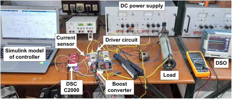
FIGURE 1. Hardware setup for the experimental results.
Besides, the nominal parameters of the boost converter is selected as follows: Vin = 15 V, Rn = 90 Ω, C = 900 μF, and L = 870 μH. The switching frequency of PWM is selected as 20 kHz and the sampling time is taken as 0.5 ms. Moreover, the gain parameters of the proposed controller are chosen as: ϕ1 = 2.6, ϕ2 = 0.2, α1 = 6.5, α2 = 1.8, ρ = 0.2, and ϵ = 0.01.
The performance of the proposed scheme is tested under three conditions as shown in Table 1. Accordingly, in condition 1, reference voltage (Vref) is varying while the other two variables, i.e., Vin and R is fixed. Whereas, load is varying in condition 2 and input voltage is changing in condition 3.

TABLE 1. Cases examined under the proposed scheme.
4.1 Simulation Analysis
The numerical simulation is performed on MATLAB/Simulink software to analyze the proposed control strategy under different conditions. Figure 2 shows the output voltage response, proposed control duty, and the time-varying adaptive gain response for all three cases.
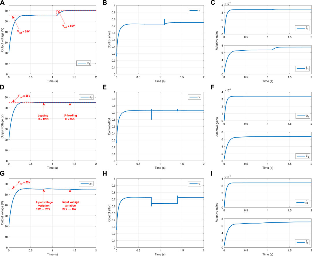
FIGURE 2. (A) Condition 1: Output voltage response. (B) Condition 1: Control duty. (C) Condition 1: Adaptive gains. (D) Condition 2: Output voltage response. (E) Condition 2: Control duty. (F) Condition 2: Adaptive gains. (G) Condition 3: Output voltage response. (H) Condition 3: Control duty. (I) Condition 3: Adaptive gains.
It can be seen from Figure 2A that the references values are changing, i.e., till 1.1 s, Vref = 55 V, and after that Vref = 60 V. Accordingly, the proposed controller effectively regulates the output voltage to the two different desired values in the same simulation. Note that the output voltage response is fast and without any overshoot or oscillations in its transient response. Moreover, the control effort in terms of duty value is generated according to the proposed law (8), whose response is shown in Figure 2B. The value of u automatically changes at time t = 1.1s when the reference value increases to 60 V. The auto-increment in u is possible due to the self-tuning of controller gains. These gains are tuned using the proposed adaptation laws, and their responses are illustrated in Figure 2C. It is evident from Figure 2C that the adaptive gains are self-adapting to a new value after 1.1 s when Vref command changes to 60 V.
The system response under resistive load variation is demonstrated in Figures 2D–F. In this condition, loading (at 0.8 s) and unloading (at 1.1 s) of load resistance occur. However, the output voltage response has no significant changes due to this load variation, as shown in Figure 2D. Thus, the proposed controller effectively tackles the load uncertainty while maintaining the desired output voltage level. The control duty and the adaptive gain responses are shown in Figures 2E,F, respectively. The slight fluctuation in the control response and small increment in the adaptive gains is due to the sudden change in load resistance value.
Similarly, the third condition of input voltage variation is tested and illustrated in Figures 2G–I. Similarly, the third condition of input voltage variation is tested and illustrated in Figure 2G. Here, the input voltage is varied from 15 to 20 V (at 0.8 s) and 20–15 V (at 1.1 s) to check the robustness performance of the proposed controller under system parameter variation. The sudden rise and the fall in the input voltage have a small effect on the output voltage response for a short duration, as shown in Figure 2G. However, once the adaptive gains tune to an appropriate value after 0.2 s from the time of variation, the output response again converges to the desired value. Figure 2H shows the change in the control duty cycle value when there are changes in the input parameter. The adaptive gain parameter
It is important to note that the chattering effect in all control responses is considerably relieved due to employing the boundary layer technique in simulation (Boiko, 2013; Saha et al., 2021).
4.2 Experimental Results
The hardware performances of the proposed scheme are also illustrated here to validate its effectiveness. Figure 3 presents four sets of actual snapshots of the output voltage and inductor current waveforms on the experimental setup using DSO. Figures 3A,B illustrate the results of the boost converter under condition 1. In Figure 3A, the output voltage initially starts from the biasing voltage. But, once the processor C2000 implements the proposed control algorithm to the hardware, the output voltage effectively reaches the reference value (i.e., 55 V). Likewise, the given controller satisfactorily forces the output voltage to a new desired value of 60 V in Figure 3B.
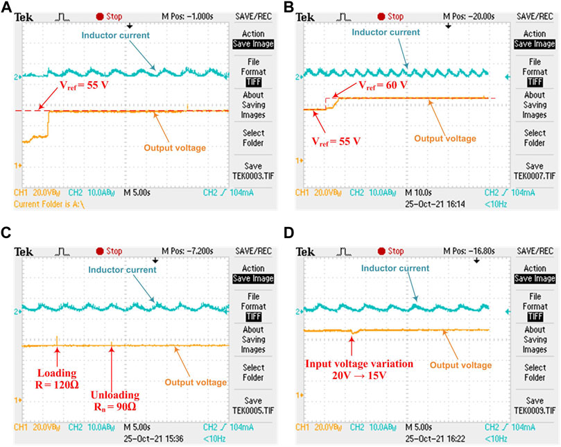
FIGURE 3. System performance under different conditions. (A) Condition 1: Vref = 55 V. (B) Condition 1: Vref = 60 V. (C) Condition 2: Load variation. (D) Condition 3: Input voltage variation.
The effect of load variation on the system performance is shown in Figure 3C, which indicates that the proposed controller perfectly tackles the change in resistive load without any significant change in the output voltage. Furthermore, Figure 3D gives a snapshot of output voltage response under the influence of input voltage fluctuation. Here, there is a small dip in the output voltage at the instant of voltage variation, but the controller effectively regulates the output to the desired voltage value quickly.
5 Conclusion
This paper presents a robust regulation control of boost converter to regulate its output voltage under various uncertainties. The proposed control scheme is designed by integrating the terminal sliding manifold with adaptive controller gains. The terminal SMC guarantees the finite-time convergence of error between the output and reference voltage. The adaptive laws enable the controller design to dynamically tune its gains without knowing the upper bound values of uncertainties. A detailed theoretical stability analysis of the closed-loop system is also proved by the Lyapunov theory. The proposed control strategy is validated through numerical and hardware analyses under various uncertainty conditions. The closed-loop system performance is found to be fast, efficient, and robust against different uncertainties. The possible extension of this research could be along the lines of implementing the proposed algorithm at a higher power level with inductance and capacitance uncertainties.
Data Availability Statement
The original contributions presented in the study are included in the article/supplementary material, further inquiries can be directed to the corresponding author.
Author Contributions
SA contributed to conception, methodology, and design of the study. SA and SW carried out the formal analysis. SA and JA organized the database and software coding. SA performed the mathematical analysis and theoretical investigation. SA and JA realized the hardware results. SA wrote the first draft of the manuscript. SA, AS, JA, SW, and ASS wrote sections of the manuscript. MN and AS supervised this work. MN and AS provide the laboratory resources. ASS arranged the funding acquisition. All authors contributed to manuscript revision, read, and approved the submitted version.
Funding
The Deanship of Scientific Research at King Khalid University funded the APC of this work through Research Groups Program under grant number (RGP.2/81/43).
Conflict of Interest
The authors declare that the research was conducted in the absence of any commercial or financial relationships that could be construed as a potential conflict of interest.
Publisher’s Note
All claims expressed in this article are solely those of the authors and do not necessarily represent those of their affiliated organizations, or those of the publisher, the editors and the reviewers. Any product that may be evaluated in this article, or claim that may be made by its manufacturer, is not guaranteed or endorsed by the publisher.
Acknowledgments
The authors extend their appreciation to the Deanship of Scientific Research at King Khalid University for funding this work through Research Groups Program under grant number (RGP.2/81/43).
References
Amrr, S. M., Alam, M. S., Asghar, M. S. J., and Ahmad, F. (2018). Low Cost Residential Microgrid System Based Home to Grid (H2G) Back up Power Management. Sustain. Cities Soc. 36, 204–214. doi:10.1016/j.scs.2017.10.016
Amrr, S. M., and Alturki, A. (2021). Robust Control Design for an Active Magnetic Bearing System Using Advanced Adaptive SMC Technique. IEEE Access 9, 155662–155672. doi:10.1109/access.2021.3129140
Amrr, S. M., Shemami, M. S., Irfan, H. K. M., and Asghar, M. S. J. (2021). “Design and Operation of a Low-Cost Microgrid-Integrated EV for Developing Countries,” in Electric Vehicle Integration in a Smart Microgrid Environment (CRC Press), 335–357. doi:10.1201/9780367423926-15
Balog, R. S., Weaver, W. W., and Krein, P. T. (2012). The Load as an Energy Asset in a Distributed Dc Smartgrid Architecture. IEEE Trans. Smart Grid 3, 253–260. doi:10.1109/tsg.2011.2167722
Bhat, S. P., and Bernstein, D. S. (2000). Finite-time Stability of Continuous Autonomous Systems. SIAM J. Control Optim. 38, 751–766. doi:10.1137/s0363012997321358
Boiko, I. M. (2013). Chattering in Sliding Mode Control Systems with Boundary Layer Approximation of Discontinuous Control. Int. J. Syst. Sci. 44, 1126–1133. doi:10.1080/00207721.2011.652233
Bouchekara, H. R. E.-H., Javaid, M. S., Shaaban, Y. A., Shahriar, M. S., Ramli, M. A. M., and Latreche, Y. (2021). Decomposition Based Multiobjective Evolutionary Algorithm for Pv/wind/diesel Hybrid Microgrid System Design Considering Load Uncertainty. Energy Rep. 7, 52–69. doi:10.1016/j.egyr.2020.11.102
Cucuzzella, M., Lazzari, R., Trip, S., Rosti, S., Sandroni, C., and Ferrara, A. (2018). Sliding Mode Voltage Control of Boost Converters in Dc Microgrids. Control Eng. Pract. 73, 161–170. doi:10.1016/j.conengprac.2018.01.009
Farrell, J. A., and Polycarpou, M. M. (2006). Adaptive Approximation Based Control: Unifying Neural, Fuzzy and Traditional Adaptive Approximation Approaches, 48. New Jersey): John Wiley & Sons.
Guo, L., and Abdul, N. M. (2021). Design and Evaluation of Fuzzy Adaptive Particle Swarm Optimization Based Maximum Power Point Tracking on Photovoltaic System under Partial Shading Conditions. Front. Energy Res. 9. doi:10.3389/fenrg.2021.712175
Guo, L., Hung, J. Y., and Nelms, R. M. (2011). Comparative Evaluation of Sliding Mode Fuzzy Controller and Pid Controller for a Boost Converter. Electr. Power Syst. Res. 81, 99–106. doi:10.1016/j.epsr.2010.07.018
Hernández-Márquez, E., Avila-Rea, C. A., García-Sánchez, J. R., Silva-Ortigoza, R., Marciano-Melchor, M., and Marcelino-Aranda, M. (2019). New “Full-bridge Buck Inverter–Dc Motor” System: Steady-State and Dynamic Analysis and Experimental Validation. Electronics 8, 1216. doi:10.3390/electronics8111216
Hernández-Márquez, E., Avila-Rea, C. A., García-Sánchez, J. R., Silva-Ortigoza, R., Silva-Ortigoza, G., Taud, H., et al. (2018). Robust Tracking Controller for a Dc/dc Buck-Boost Converter–Inverter–Dc Motor System. Energies 11, 2500. doi:10.3390/en11102500
ImdadullahAmrr, S. M., Iqbal, A., and Asghar, M. J. (2021). Comprehensive Performance Analysis of Flexible Asynchronous Ac Link under Various Unbalanced Grid Voltage Conditions. Energy Rep. 7, 750–761. doi:10.1016/j.egyr.2021.01.028
Khan, T., and Sundareswaran, K. (2014). “Voltage Regulation Enhancement in a Buck Type Dc-Dc Converter Using Queen Bee Evolution Based Genetic Algorithm,” in 2014 IEEE 6th India International Conference on Power Electronics (IICPE) (IEEE), 1–6. doi:10.1109/iicpe.2014.7115836
Kobaku, T., Jeyasenthil, R., Sahoo, S., and Dragicevic, T. (2021). Experimental Verification of Robust Pid Controller under Feedforward Framework for a Nonminimum Phase Dc–Dc Boost Converter. IEEE J. Emerg. Sel. Top. Power Electron. 9, 3373–3383. doi:10.1109/jestpe.2020.2999649
Leon, J. I., Vazquez, S., and Franquelo, L. G. (2017). Multilevel Converters: Control and Modulation Techniques for Their Operation and Industrial Applications. Proc. IEEE 105, 2066–2081. doi:10.1109/jproc.2017.2726583
Liu, L., Zhao, Y., Chang, D., Xie, J., Ma, Z., Sun, Q., et al. (2018). Prediction of Short-Term Pv Power Output and Uncertainty Analysis. Appl. energy 228, 700–711. doi:10.1016/j.apenergy.2018.06.112
Martínez-Treviño, B. A., Jammes, R., El Aroudi, A., and Martínez-Salamero, L. (2017). Sliding-mode Control of a Boost Converter Supplying a Constant Power Load. IFAC-PapersOnLine 50, 7807–7812. doi:10.1016/j.ifacol.2017.08.1055
Muktiadji, R. F., Ramli, M. A., Bouchekara, H. R., Seedahmed, M., and Budiman, F. N. (2022). Control of Boost Converter Using Observer-Based Backstepping Sliding Mode Control for Dc Microgrid. Front. Energy Res. 10, 152. doi:10.3389/fenrg.2022.828978
Mummadi, V. (2011). Design of Robust Digital Pid Controller for H-Bridge Soft-Switching Boost Converter. IEEE Trans. Industrial Electron. 58, 2883–2897. doi:10.1109/tie.2010.2077615
Nizami, T. K., and Chakravarty, A. (2020). Neural Network Integrated Adaptive Backstepping Control of Dc-Dc Boost Converter. IFAC-PapersOnLine 53, 549–554. doi:10.1016/j.ifacol.2020.06.092
Park, H.-H., and Cho, G.-H. (2014). A Dc–Dc Converter for a Fully Integrated Pid Compensator with a Single Capacitor. IEEE Trans. Circuits Syst. II Express Briefs 61, 629–633. doi:10.1109/tcsii.2014.2327351
Saha, S., Amrr, S. M., Nabi, M. U., and Iqbal, A. (2019). Reduced Order Modeling and Sliding Mode Control of Active Magnetic Bearing. IEEE Access 7, 113324–113334. doi:10.1109/access.2019.2935541
Saha, S., Amrr, S. M., Saidi, A. S., Banerjee, A., and Nabi, M. (2021). Finite-time Adaptive Higher-Order Smc for the Nonlinear Five Dof Active Magnetic Bearing System. Electronics 10, 1333. doi:10.3390/electronics10111333
Saidi, A. S. (2022). Impact of Grid-Tied Photovoltaic Systems on Voltage Stability of Tunisian Distribution Networks Using Dynamic Reactive Power Control. Ain Shams Eng. J. 13, 101537. doi:10.1016/j.asej.2021.06.023
Shen, H., Tao, P., Lyu, R., Ren, P., Ge, X., and Wang, F. (2021). Risk-constrained Optimal Bidding and Scheduling for Load Aggregators Jointly Considering Customer Responsiveness and Pv Output Uncertainty. Energy Rep. 7, 4722–4732. doi:10.1016/j.egyr.2021.07.021
Singh, R., Amrr, S. M., and Asghar, M. J. (2021). Supervisory Control Strategy for the Effective Solar Energy Utilization in a Residential Microgrid System Using a Cost-Effective Controller. Int. J. Electr. Power & Energy Syst. 132, 107170. doi:10.1016/j.ijepes.2021.107170
Slotine, J.-J. E., and Li, W. (1991). Applied Nonlinear Control, 199. Englewood Cliffs, NJ): Prentice-Hall.
Tahri, A., El Fadil, H., Rachid, A., Eric, M., and Giri, F. (2019). A Nonlinear Controller Based on a High Gain Observer for a Cascade Boost Converter in a Fuel Cell Distributed Power Supply System. IFAC-PapersOnLine 52, 91–96. doi:10.1016/j.ifacol.2019.12.627
Taleb, M., Plestan, F., and Bououlid, B. (2015). An Adaptive Solution for Robust Control Based on Integral High-Order Sliding Mode Concept. Int. J. Robust Nonlinear Control 25, 1201–1213. doi:10.1002/rnc.3135
Tan, S.-C., Lai, Y.-M., Cheung, M. K., and Tse, C. K. (2005). On the Practical Design of a Sliding Mode Voltage Controlled Buck Converter. IEEE Trans. power Electron. 20, 425–437. doi:10.1109/tpel.2004.842977
Tan, S.-C., Lai, Y.-M., Chi, K. T., Martinez-Salamero, L., and Wu, C.-K. (2007). A Fast-Response Sliding-Mode Controller for Boost-type Converters with a Wide Range of Operating Conditions. IEEE Tr Ind Ele 54, 3276–3286. doi:10.1109/tie.2007.905969
Tan, S.-C., Lai, Y., Tse, C. K., and Cheung, M. K. (2006). Adaptive Feedforward and Feedback Control Schemes for Sliding Mode Controlled Power Converters. IEEE Tr Power Ele 21, 182–192. doi:10.1109/tpel.2005.861191
Utkin, V., Poznyak, A., Orlov, Y., and Polyakov, A. (2020). Conventional and High Order Sliding Mode Control. J. Frankl. Inst. 357, 10244–10261. doi:10.1016/j.jfranklin.2020.06.018
Utkin, V., and Shi, J. (1996). “Integral Sliding Mode in Systems Operating under Uncertainty Conditions,” in Proceedings of 35th IEEE conference on decision and control (IEEE) 4, 4591–4596.
Utkin, V. (1977). Variable Structure Systems with Sliding Modes. IEEE Trans. Automatic Control 22, 212–222. doi:10.1109/tac.1977.1101446
Wai, R.-J., and Shih, L.-C. (2011). Design of Voltage Tracking Control for Dc–Dc Boost Converter via Total Sliding-Mode Technique. IEEE Tr Indust Elect 58, 2502–2511. doi:10.1109/tie.2010.2066539
Wang, H., Man, Z., Kong, H., Zhao, Y., Yu, M., Cao, Z., et al. (2016). Design and Implementation of Adaptive Terminal Sliding-Mode Control on a Steer-By-Wire Equipped Road Vehicle. IEEE Trans. Industrial Electron. 63, 5774–5785. doi:10.1109/tie.2016.2573239
Wang, Z., Li, S., and Li, Q. (2020). Continuous Nonsingular Terminal Sliding Mode Control of Dc-Dc Boost Converters Subject to Time-Varying Disturbances. IEEE Trans. Circuits Syst. II Express Briefs 67, 2552–2556. doi:10.1109/tcsii.2019.2955711
Wei, M., Lin, S., Zhao, Y., Wang, H., and Liu, Q. (2021). An Adaptive Sliding Mode Control Based on Disturbance Observer for Lfc. Front. Energy Res. 555. doi:10.3389/fenrg.2021.733910
Yazici, I., and Yaylaci, E. K. (2016). Fast and Robust Voltage Control of Dc–Dc Boost Converter by Using Fast Terminal Sliding Mode Controller. IET Power Electron. 9, 120–125. doi:10.1049/iet-pel.2015.0008
Yin, Y., Liu, J., Marquez, A., Lin, X., Leon, J. I., Vazquez, S., et al. (2020). Advanced Control Strategies for Dc–Dc Buck Converters with Parametric Uncertainties via Experimental Evaluation. IEEE Trans. Circuits Syst. I Regul. Pap. 67, 5257–5267. doi:10.1109/tcsi.2020.3009168
Yu, S., Yu, X., Shirinzadeh, B., and Man, Z. (2005). Continuous Finite-Time Control for Robotic Manipulators with Terminal Sliding Mode. Automatica 41, 1957–1964. doi:10.1016/j.automatica.2005.07.001
Keywords: boost converter, uncertain system, finite-time theory, Lyapunov stability analysis, adaptive control, sliding mode control
Citation: Amrr SM, Ahmad J, Waheed SA, Sarwar A, Saidi AS and Nabi M (2022) Finite-Time Adaptive Sliding Mode Control of a Power Converter Under Multiple Uncertainties. Front. Energy Res. 10:901606. doi: 10.3389/fenrg.2022.901606
Received: 22 March 2022; Accepted: 13 April 2022;
Published: 03 May 2022.
Edited by:
Marif Daula Siddique, Virginia Tech, United StatesReviewed by:
Asaad Mohammad, Auckland University of Technology, New ZealandZeeshan Ahmad Khan, Volkswagen Group, Germany
Mahetab Alam, IIT Ropar, India
Copyright © 2022 Amrr, Ahmad, Waheed, Sarwar, Saidi and Nabi. This is an open-access article distributed under the terms of the Creative Commons Attribution License (CC BY). The use, distribution or reproduction in other forums is permitted, provided the original author(s) and the copyright owner(s) are credited and that the original publication in this journal is cited, in accordance with accepted academic practice. No use, distribution or reproduction is permitted which does not comply with these terms.
*Correspondence: Syed Muhammad Amrr, c3llZGFtcnJAZ21haWwuY29t