 Wenli Wei1*
 Shanlin Li
- 1Center of Mass Entrepreneurship and Innovation State Grid Zhejiang Electric Power Co., Ltd., Hangzhou, China
- 2School of Electrical Engineering, Southeast University, Nanjing, China
In the contemporary distribution network, unbalanced and harmonic distortions have been considered some major power quality problems, which have escalated especially due to the high penetration of unbalanced and nonlinear loads. This study first analyzes the dispute around the distortion restraint and grid-connected unbalanced/harmonic current suppression quantitatively and proposes a distributed control strategy that facilitates an effective suppression of output voltage and grid-connected current, with accurate unbalanced/harmonic power sharing. Compared with the majority of existing studies only addressing the voltage-controlled mode (VCM) inverters, our scheme can also be applied to current-controlled mode (CCM) inverters without adding additional current regulation loops. The proposed control strategy is independent of line parameters and robust to load changes. The corresponding small-signal dynamic model is constructed to analyze the system stability and the controller hardware-in-the-loop simulations aid in determining the outcome of the proposed strategy.
Introduction
With the continuous advancement of smart grid construction, renewable energy resources are connected to the distribution network in the form of distributed generation (DG) (Zheng et al., 2017). Meanwhile, the high-density distributed generations are connected to the distribution network, which change the radial structure of the traditional distribution network and increase the difficulty of the distribution network control (Koutsoukis et al., 2018). With the extensive application of nonlinear loads, unbalanced loads, and power electronic equipment, harmonic and unbalanced voltage management has become an issue that cannot be ignored in the distribution network. The distribution network is connected to the main grid through the point of common coupling (PCC) (Kulmala et al., 2014), so the voltage quality of PCC is critical. The loads and generators will be affected by unbalanced or harmonic currents if the PCC voltage is three-phase unbalanced or distorted (Liu et al., 2019a). Meanwhile, the poor harmonic/unbalanced power sharing will also cause some inverters to be overloaded and affect equipment life.
Some control methods have been proposed to achieve harmonic/unbalanced voltage suppression and accurate power sharing. Using resistive active power filters (APF) (Hashempour et al., 2016; Lee and Hu, 2016; Sun et al., 2016) to absorb harmonic and unbalanced currents is the traditional solution, but this strategy is highly dependent on line parameters. Considering the similarity in structure between grid-connected inverter and APF, and the fact that there are a large number of DGs connected to the distribution network, the grid-connected inverter can be used to control the power quality of the distribution network while generating electricity. In De and Ramanarayanan (2010)and Vandoorn et al. (2012), the harmonic/unbalanced power sharing is achieved by adding virtual impedance in the control loop of the negative and harmonic sequence of DGs, but the substantial virtual impedance leads to the degradation of the output voltage quality. Some researchers applied droop control to negative sequence and harmonic frequencies, contributing to the improvement of the voltage quality of PCC, but the sharing of harmonic and unbalanced power was only slightly ameliorated (Moussa et al., 2018; Zhong, 2019). To improve the control effect, the control strategy combining virtual impedance and droop control is proposed (Sreekumar and Khadkikar, 2016; Vijay et al., 2021), but the droop coefficient selection needs precise line-impedance parameters. By injecting a small signal and measuring the voltage drop caused by the small signal, the accurate line impedance can be calculated (Liu et al., 2019b), but this method is quite complicated to implement in the existing distribution network. These are all decentralized control methods, which do not require communication lines, but the non-error control effect is challenging to achieve.
The outputs of all DGs are collected through the centralized controller (He and Li, 2012; He et al., 2015; Hoang and Lee, 2019), and then commands are issued to balance the difference between line impedances. However, the centralized control relies too much on the global controller and the communication link, and any damage to the communication link can lead to the failure of the whole network control. In addition, the entire communication network needs to be rebuilt when a new DG is added, which cannot meet the requirement of plug-and-play DGs. Therefore, distributed control strategies have been widely used in DG control. In distributed control, each DG only needs to communicate with its neighbors, which enhances the reliability and flexibility of the system (Tang et al., 2015; Golsorkhi et al., 2021; Lu et al., 2022). In (Golsorkhi et al., 2021), the sharing of harmonic and negative sequence power is adopted as the second control objective in hierarchical control. In Lu et al. (20220, the event-triggered mechanism is used to reduce the distributed network’s communication traffic while maintaining the distribution of superior harmonic and unbalanced control effects.
Although a variety of methods have been proposed to control harmonic and unbalanced voltage, most of the existing literature focuses on the control strategies of voltage-controlled mode (VCM) inverters, whereas the coordinated control in different modes, that is, VCM and current-controlled mode (CCM), is barely studied. Moreover, when some harmonic and unbalanced control strategies are extended to CCM inverters, additional current regulation loops need to be added (Liu et al., 2016; Campos-Gaona et al., 2017), and even droop-based control strategies (Sreekumar and Khadkikar, 2016; Moussa et al., 2018; Zhong, 2019) are difficult to apply for CCM inverters. The method of Zhao et al. (2018) considers the coexistence of VCM and CCM, but the VCM inverter only plays the role of voltage and frequency support, and the CCM inverter suppresses harmonics by adding a feedforward compensation loop. In He et al. (2017), a coordinated control for the compensation of grid voltage harmonics and the local nonlinear load current is proposed for two CCM units without any VCM units. In the method of Zeng et al. (2014), harmonic compensation is achieved by adding a fixed virtual admittance in the control loop of CCM inverters. It should be noted that the method of Zhao et al. (2018) and Zeng et al. (2014) is only applicable to CCM inverters. There is also a small amount of literature considering the coordinated control of VCM and CCM. In Mousazadeh Mousavi et al. (2018), control strategies based on droop (VCM) and reverse droop (CCM) have been proposed, but this decentralized strategy is difficult to reduce the harmonic THD to extremely low values. The aforementioned studies all believe that the main grid side is pure, and the suppression of harmonic/unbalanced current on the connecting line when there are unbalanced and harmonic sources on the main grid side is rarely considered.
In order to solve the aforementioned problems, the relationship between PCC voltage suppression, VCM and CCM power sharing, and grid-connected current suppression is comprehensively and theoretically analyzed first in this study when the main grid side contains harmonic/unbalanced sources. Then, a consensus-based distributed suppression scheme is proposed, which suppresses unbalanced and harmonic loads and shares the power between VCM and CCM inverters. Meanwhile, a small-signal model of the proposed strategy is established, and its stability under parameter changes is analyzed. The main contributions of this study are summarized as follows:
1) To quantitatively evaluate the effect of unbalanced power sharing and power quality recovery, a control strategy is proposed to ensure accurate unbalanced power sharing between VCM and CCM inverters, in contrast to most of the existing studies that only address the VCM.
2) The conflict between PCC voltage suppression and grid-connected harmonic/unbalanced current suppression is analyzed when the main grid side contains harmonic/unbalanced sources, and a corresponding strategy is proposed to suppress them simultaneously by the dynamic voltage regulator (DVR).
3) Compared with the centralized control strategy, the proposed strategy based on the distributed consensus algorithm can improve the reliability and scalability of DGs.
This study is organized as follows: The Problem Formulation section introduces and theoretically analyzes the distribution network system with VCM and CCM inverters. The Proposed Control Scheme section shows the proposed distributed control strategy for VCM and CCM, and explores the stability by establishing a small-signal model. In the Simulation Results section, the effectiveness of the strategy is verified by real-time experimental results. Finally, the Conclusion section concludes the study.
Problem Formulation
Figure 1 shows a distribution network composed of multiple parallel DGs including VCM and CCM inverters. Each DG is connected to the network through its filter and connection impedance, while linear loads, nonlinear loads, and unbalanced loads are all in the distribution network.
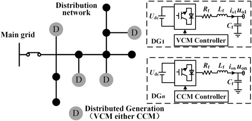
FIGURE 1. Structural diagram of the distribution network with VCM and CCM inverters.
To simplify the analysis, Figure 2 depicts an equivalent circuit consisting of a voltage-controlled inverter and a current-controlled inverter in parallel, where the superscript h represents the harmonic or unbalanced component of the relevant variable. The unbalanced component can be regarded as the −1 harmonic (when h = −1 represents the unbalanced component) because it affects the negative sequence–equivalent circuit. At the same time, the VCM inverter is modeled as a controlled voltage source us1 connected in series with the output impedance Zo1, the CCM inverter is modeled as a controlled current source is2 connected in parallel with the output impedance Zo2, and the nonlinear and unbalanced loads at PCC are assumed to be current sources ihL in the analysis. The harmonic and unbalanced voltage on the main grid side is considered voltage sources.where iho1 and iho2 are the output currents of DG1 and DG2; uho1 and uho2 are the output voltages of DG1 and DG2, respectively; Zho1 and Zho2 (Zhc1 and Zhc2) are the output impedances (line impedances) of DG1 and DG2, respectively; uhpcc is the PCC harmonic/unbalanced voltage; Zhg is the impedance of the grid-connected line; and uhg is the harmonic/unbalanced component of the grid voltage. The hth DG output current and the PCC voltage are expressed as:
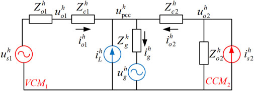
FIGURE 2. Equivalent circuit with a VCM and a CCM.
The hth grid-connected current ihg can be simply expressed as:
The system parameters of VCM and CCM in Table 1 are taken, and then the curves of output current iho1, iho2, PCC voltage uhpcc, and grid-connected harmonic current ihg with uhs1 and uhs2 are drawn as shown in Figure 3.

TABLE 1. Electrical and control system parameters.
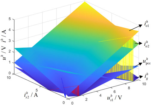
FIGURE 3. Resultant ih oi, uh pcc, and ih g in case of different uh s1 and ih s2.
The red, blue, and yellow sections in Figure 3 represent VCM and CCM outputs that satisfy power sharing (iho1 = iho2), PCC voltage suppression (uhpcc = 0), and grid-connected current suppression (ihg = 0), respectively. To formulate the problem more clearly, the intersection between hypersurfaces iho1 and iho2 and the intersection between hypersurfaces uhpcc, ihg, and the zero plane is projected onto the (uhs1, uhs2) plane. Figure 4 shows the feasible range, where the red grid represents the range of 0–5% of the PCC voltage, the yellow grid represents the range of 0–5% of the grid-connected current, and there is a small part in the area where the two grids intersect with the feasible domain. However, the upper limit of the voltage VUF is only 2%, and with the increase of the harmonic voltage THD on the main grid side, the feasible region will gradually shrink until it disappears. Therefore, considering the sensitive loads at PCC, we need to ensure that the harmonic and unbalanced voltages are zero, and it is difficult to suppress the voltage and harmonic current at the same time.
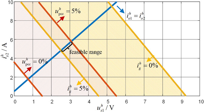
FIGURE 4. Feasible ranges for the test case.
It can be seen from the aforementioned analysis that power sharing and voltage compensation can be achieved between VCM and CCM inverters. Therefore, this study proposes a closed-loop control method directly acting on the modulation signal to achieve high-precision power sharing. At the same time, a dynamic voltage regulator (DVR) is added to suppress the grid-connected current for the large harmonic and unbalanced components on the main grid side.
Proposed Control Scheme
In order to suppress harmonics and unbalanced voltage and share corresponding to power between VCM and CCM inverters, a control scheme that acts directly on the modulated signal was proposed in this section. The control structure is shown in Figure 5, and the appropriate unbalanced voltage (unbalanced current) compensation was calculated through two parts of suitable virtual impedances. Meanwhile, due to the conflict between the grid-connected current suppression and the PCC voltage complete suppression, the grid-connected harmonic/unbalanced current is suppressed by DVR. The proposed control strategy for both VCM and CCM inverters is described in detail in the following section.
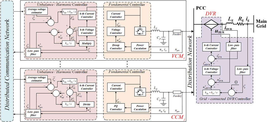
FIGURE 5. Block diagram of the proposed control architecture.
Unbalanced Voltage Suppression and Unbalanced Power Sharing
For accurate power sharing and PCC voltage suppression, the virtual unbalanced/harmonic impedance of DGi (Zhviri, i = −1, −5,⋯, n) consists of two controllable parts:
where ZhHi is the impedance to ensure the power sharing, and ZhVi is the negative impedance to ensure the voltage quality of PCC.
The proposed method of unbalanced power sharing based on distributed control is as shown in Figure 6. The unbalanced current sharing can represent the power sharing due to the output voltage of DGs being within a certain range,where aij is the adjacency element of the distributed communication topology, aij>0 means that DGi can receive information from DGj, and otherwise aij = 0. If each node i ∈ {1,. . ., n} assigned a scalar value xi, the average consensus update rule is for node i to adjust its value according to:
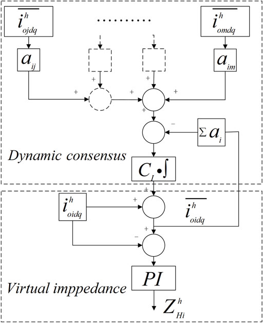
FIGURE 6. Proposed power sharing based on distributed control.
This average process will lead all variables xi to converge to a common value xi = xj = const, when the communication network is connected. Under the consensus control, DGs’ unbalanced current sharing error can be solved. The current correction is provided to every DG based on the average consensus rule to calculate virtual impedance:
where
After acquiring the average harmonic current correction, the virtual impedance ZhHi can be calculated as:
where kHpi and kHii are the proportional coefficients and integral coefficient of the PI controller in the d、q coordinate system.
Then, the second virtual impedance part ZhVi is calculated by the PCC voltage components extracted by the low-pass filter:
where uhref and uhpcc represent the target value and the actual value of the hth unbalanced PCC voltage, respectively. In this study, in order to completely suppress harmonic and unbalanced components, the target value is generally set to zero.
Then, (8) and (9) were substituted into (5) to get the virtual impedance Zhviri under the hth unbalanced component.
It should be noted that the calculation of the averaged virtual impedance does not require the information of line impedance between each DG and PCC.
Once the virtual impedance of each DG is determined, the VCM voltage compensation and CCM current compensation are calculated as follows:
Finally, VCM inverters generate the output voltage signal through the conventional voltage and current double loop, and CCM inverters only need the current loop to generate the output current signal.
Grid-Connected Unbalanced Current Suppression
The smooth on/off-grid switching and grid-connected current suppression need to be considered in a distribution network with harmonic and unbalanced voltage on the main grid side. In the islanded mode, the frequency and voltage of the distribution network are determined by all DGs and loads, so coordinated control of each distributed unit is required. The switching process between islanded and grid-connected mode is as follows:
As shown in Figure 7, it is necessary to reduce the harmonic voltage THD and unbalanced voltage VUF at PCC to the specified range before grid connection. According to the IEEE 519-1992 standard (IEEE, 2010), the PCC voltage needs to meet the following conditions: 1) the voltage single harmonic HDh < 3% and the voltage total harmonic THD <5%; 2) the maximum allowable voltage unbalance VUF is 2%. In order to ensure stable operation and avoid interference, the control target in this study is more stringent. The target values of PCC harmonic voltage and unbalance are set to zero. At the same time, the phase angle difference between PCC and the grid side will bring the impact of active power, so it is also necessary to pre-synchronize the fundamental phase angle:
where Δθ is the adjustment amount of the output phase angle of the VCM inverter; kθp and kθi are the proportional coefficient and integral coefficient of the phase angle pre-synchronization controller, respectively.
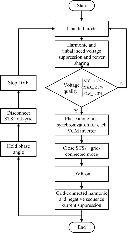
FIGURE 7. Flow chart of the distribution network control.
After the grid-connected operation, the grid-connected harmonic and unbalanced currents appeared caused by the harmonic and unbalanced voltage on the main grid side. Based on the analysis in the Problem Formulation section, it is difficult to achieve both the PCC voltage suppression and the complete suppression of the grid-connected current only by the local controller. Therefore, the DVR controlled by a grid-connected current loop is applied in the system.
Then, the equations of the PCC voltage and grid-connected harmonic current are changed as follows:
From Equations 12, 13, it can be known that the influence of harmonic and unbalanced voltage on the grid side can be eliminated through DVR. So, the output voltage of DVR can be calculated by the difference between the grid-connected current and the target value:
The phase angle needs to be maintained when the distribution network changed to the islanded mode, and DVR should stop when the grid is disconnected. Of course, the control effect of the local PCC voltage suppression and power sharing controller is not affected.
Stability Analysis
In order to analyze the stability of this harmonic/unbalanced control scheme, a small-signal dynamic model based on Figure 8 is established in this section. The small-signal model of the system consists of three parts: the VCM inverter, the CCM inverter, and the grid-connected control. Given the focus of this study, the proposed model only considers the harmonics/unbalance control loop.
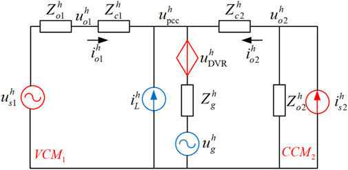
FIGURE 8. Equivalent circuit with DVR.
The VCM inverter can be expressed as
where Rhe1 and Lhe1 are the hth equivalent output resistance and inductance of the VCM inverter Rhe1 = Rh01 + Rhc1 and Lhe1 = Lh01 + Lhc1; Rh01 and Rhc1 (Lh01 and Lhc1) are the output and transmission line resistances (inductances), respectively; Δiho1d and Δiho1q are the output unbalanced currents at dq axes, respectively. Then, the unbalanced outputs uhs1d and Δuhs1q of VCM are generated according to Equation 10.
The CCM inverter can be expressed as
where Rhc2 and Lhc2 are the equivalent hth resistance and inductance of the transmission line of the CCM inverter; the local output voltage Δuho2d and Δuho2q of the CCM inverter can be calculated by the following equations.
The corresponding virtual impedance of each DG can be expressed as
where ΔxHidq and ΔxVdq are the auxiliary states.
The grid-connected part can be expressed as
where Rhg and Lhg are the grid-connected equivalent resistance and inductance; Δihgd and Δihgq are the grid-connected currents at the d-axis and q-axis, respectively. The output voltage value of DVR can be calculated as follows:
where ΔxDVRdq is also an auxiliary state. Finally, the three parts are connected in series through the PCC voltage Δuhpcc, according to Kirchhoff’s law:
where RhL and LhL are the equivalent resistance and inductance of the loads at PCC. By combining the formulas (15)-(22), the state equation of the entire system can be expressed as
where state x includes [Δiho1dq, Δiho2dq, Δihgdq, ΔxH1dq, ΔxH2dq, ΔxVdq, and ΔxDVRdq]T; d includes ΔihLdq and the harmonic/unbalanced voltage Δuhgdq contained in the grid.
In this section, the effect of parameter perturbation is studied as an example of the proportional coefficient in the virtual impedance calculation section. Because there are six eigenvalues of the system far away from the imaginary axis, the remaining eight eigenvalues closer to the imaginary axis will have a greater impact on the system stability. The changing trend of the eigenvalues with the increase of the parameter kHp is shown in the figure. As shown in Figure 9, all eigenvalues are in the left half-plane when the parameter kHp gradually increases from 0.3 to 2.1, and except for the fixed eigenvalues λ1 and λ2, the rest of the eigenvalues are all changing in the direction away from the imaginary axis, thus indicating that the control system has good stability.
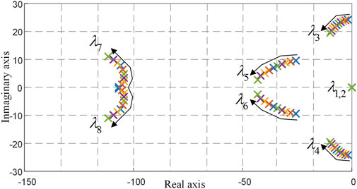
FIGURE 9. Eigenvalues with control parameter change 0.3 ≤ kHp ≤2.1.
Simulation Results
In order to verify the effectiveness of the proposed strategy, the strategy was applied to a test distribution network composed of three VCM inverters and two CCM inverters through the controller hardware-in-the-loop platform, as shown in Figure 10. The main circuit structure of the distribution network is constructed by RT-LAB (real-time simulator, OPAL-RT5700), and five DSPs (TMS320F28377) act as controllers of VCM and CCM inverters, respectively. The switchboard is utilized for auto-addressing of data exchange among the real time-simulator and local and adjacent DSPs through the UDP/IP communication protocol. The communication frequency is set to 2.5 kHz. The nonlinear loads consist of rectifiers, filters, and load RNL, the unbalanced loads RUL consist of loads connected only to AB phases, and the linear loads are resistive and inductive. In this test distribution network, the 5th and 7th harmonics account for a very high proportion and are considered to be the main harmonic frequencies. The specific control parameters are listed in Table 1.
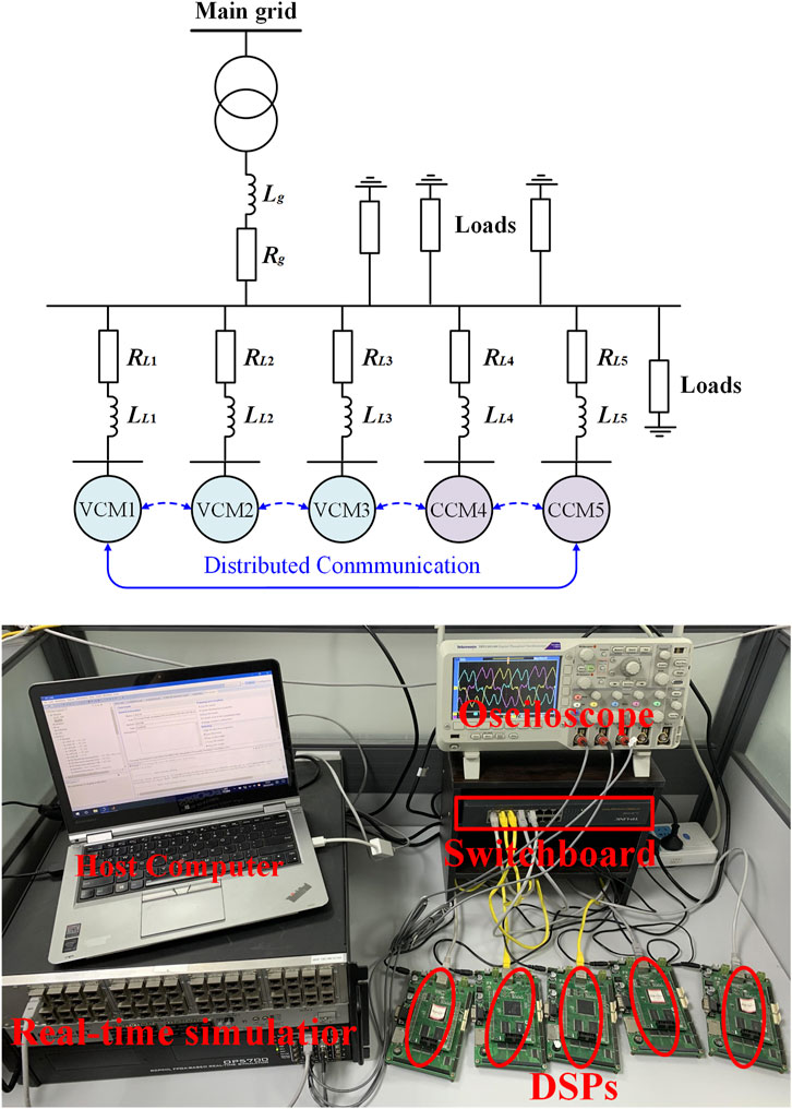
FIGURE 10. Structure diagram and controller hardware-in-the-loop platform of the simulation distribution network.
Voltage Suppression and Power Sharing Performance
In this case, the performance of the proposed voltage suppression and power sharing control strategy are investigated. At first, the distribution network ran smoothly with only linear loads. There are only two steps:
Step1. Input nonlinear and unbalanced loads at t = 0.5s, the resistance part of the nonlinear load at this time RNL = 10Ω, and the unbalanced load between AB phases is RUL = 2.5Ω.
Step2. 5th and 7th harmonic, unbalanced voltage suppression, and corresponding power sharing controllers are activated at t = 2s.It can be seen from Figure 11 that the PCC voltage quality is greatly improved after the strategy application. As shown in the 1st result plot of Figure 11A, before the strategy was applied, the PCC voltage VUF reached 4.9%, and the voltage THD reached 8.53%, which exceeded the limit standards of VUF<2% and THD<5%. After the strategy was applied, we can see the voltage VUF is reduced to 0.2%, and the voltage THD is reduced to 1.23% in the 2nd result plot of Figure 11A. The change in the PCC voltage VUF is shown in Figure 12. It can be seen that the voltage VUF reaches a very low value of about 0.5s. However, in this simulation, only the 5th and 7th harmonic controllers with the highest content are added, and the higher harmonics are not suppressed, so the harmonics can theoretically be reduced to near zero. The 1st, 2nd, and 3rd of result plots of Figure 11B show the unbalanced 5th and 7th harmonic power output of 5 DGs, respectively. It can be seen from Figure 11B that during Step 1, the generation of harmonic/unbalanced voltage leads to the failure of corresponding power sharing, but under the control of the proposed strategy, the unbalanced fifth and seventh harmonic power are quickly shared and the voltage suppression is completed at the same time. Therefore, the effectiveness of the proposed harmonic control scheme is verified.
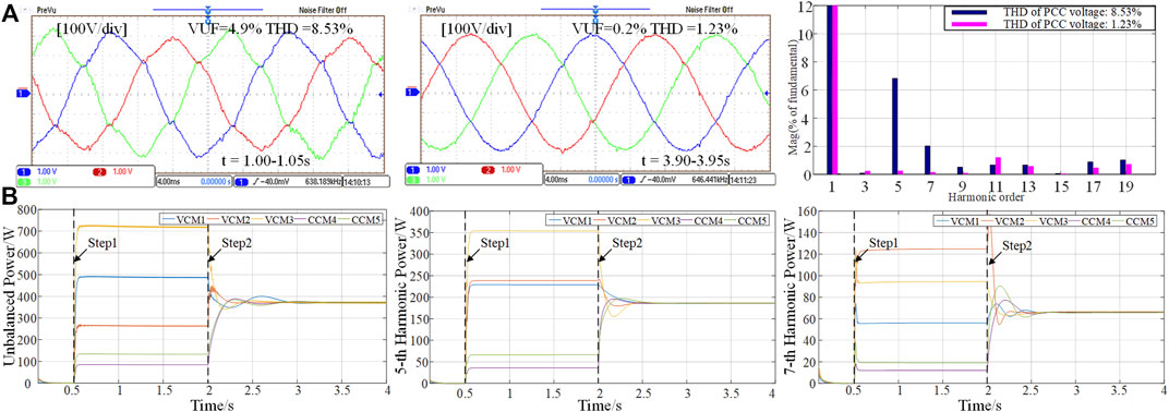
FIGURE 11. Simulation results of voltage suppression and power sharing control. (A) Harmonic and unbalanced voltage at PCC and THD of voltage at different times. (B) Power performance of unbalanced 5th and 7th harmonic power.
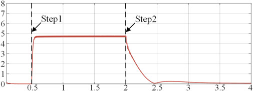
FIGURE 12. The change of the PCC voltage VUF.
With Unbalanced and Harmonic Voltage on the Main Grid Side
This case not only shows the robustness of the proposed strategy to load changes but also shows the whole process of grid connection. There are the following six steps:
Step 1. Input nonlinear and unbalanced loads at t = 0.5s, the resistance of the nonlinear load RNL is changed to 6Ω, and the unbalanced load between AB phases is RUL = 2.5Ω.
Step 2. 5th and 7th harmonics and unbalanced voltage suppression and corresponding power sharing controllers are activated at t = 2s.
Step 3. The pre-synchronization of grid connection is performed at t = 4s.
Step 4. The grid connection operation is performed at t = 4.5s.
Step 5. The harmonic and unbalanced sources on the main grid side are input at t = 5s, containing 6% unbalanced, 10% fifth harmonic, and 5% seventh harmonic voltage.
Step 6. DVR on the grid-connected current suppression controller is added at t = 5.5s.
As shown in the 1st and 2nd result plots of Figure 13A, the voltage of PCC was also improved after the strategy was applied, the VUF was reduced from 5.03 to 0.24%, and the THD was reduced from 9.95 to 1.89%. The specific harmonic FFT analysis is shown in the 3rd plot of Figure 13A; the 5th and 7th harmonics have been basically reduced to zero, but there are still some high-order harmonics. The 1st and 2nd result plots of Figure 13B show the control effect of grid-connected current after adding grid-side harmonics and unbalanced sources. It is also seen that the grid-connected current distortion before the strategy application is obvious, the current THD is as high as 28.83%, and the current unbalance factor (CUF) is as high as 7.83%. After the control application of DVR, CUF is reduced to 0.19%, THD is reduced to 1.25%, and the grid-connected current returns to a smooth sine.
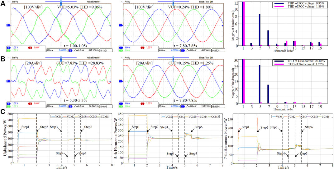
FIGURE 13. Simulation results of proposed control with unbalanced and harmonic voltage on the main grid side. (A) Harmonic and unbalanced voltage at PCC and THD of voltage at different times. (B) Harmonic and unbalanced grid-connected current and THD of current at different times. (C) Power performance of unbalanced 5th and 7th harmonic power.
The 1st, 2nd, and 3rd of result plots of Figure 13C show the unbalanced 5th and 7th harmonic power output of 5 DGs, respectively. It can be seen from Figure 13C that in the Step 2, the unbalanced fifth and seventh harmonics powers have been well shared; in Step 4, the output unbalance and harmonic power of each DG has only slight fluctuations, which proves that the grid connection is relatively smooth; in Step 5, the corresponding power output by five DGs still maintains the same trend of change when the main grid side harmonic and unbalanced sources are added; in Step 6, the unbalanced and harmonic power of each DG output returns to the original output value after a brief fluctuation after DVR works. Therefore, the simulation results verify the effectiveness of the proposed strategy with unbalanced and harmonic voltage on the main grid side, and its robustness to load changes.
Conclusion
In this study, a distributed harmonic/unbalanced control strategy is proposed for the distribution network with VCM and CCM inverters, aiming at sharing the harmonic/unbalanced power among them. Meanwhile, the conflict between the suppression of unbalanced/harmonic current flowing into the main grid and PCC distortion restraint is quantitatively analyzed, and a control strategy is proposed to achieve effective suppression of both simultaneously. Furthermore, the method is robust to load change and easy to implement.
Data Availability Statement
The original contributions presented in the study are included in the article/Supplementary Material; further inquiries can be directed to the corresponding author.
Author Contributions
WW and SL proposed the methodology; WW and TC conducted the theoretical analysis as well as simulation verification; SW wrote the original draft which was reviewed and edited by SL and NM. All authors agree to be accountable for the content of the work.
Funding
This research was supported by the science and technology project of State Grid Zhejiang Electric Power Co., Ltd. under Grant B311JZ210002.
Conflict of Interest
The authors declare that this study received funding from the science and technology project of State Grid Zhejiang Electric Power Co., Ltd. under Grant B311JZ210002. The funder had the following involvement in the study: provide the system model parameters and practical application scenario for the case study.
Publisher’s Note
All claims expressed in this article are solely those of the authors and do not necessarily represent those of their affiliated organizations, or those of the publisher, the editors, and the reviewers. Any product that may be evaluated in this article, or claim that may be made by its manufacturer, is not guaranteed or endorsed by the publisher.
References
Campos-Gaona, D., Pena-Alzola, R., Monroy-Morales, J. L., Ordonez, M., Anaya-Lara, O., and Leithead, W. E. (2017). Fast Selective Harmonic Mitigation in Multifunctional Inverters Using Internal Model Controllers and Synchronous Reference Frames. IEEE Trans. Ind. Electron. 64, 6338–6349. doi:10.1109/tie.2017.2682003
De, D., and Ramanarayanan, V. (2010). Decentralized Parallel Operation of Inverters Sharing Unbalanced and Nonlinear Loads. IEEE Trans. Power Electron. 25, 3015–3025. doi:10.1109/tpel.2010.2068313
Golsorkhi, M. S., Hill, D. J., and Baharizadeh, M. (2021). A Secondary Control Method for Voltage Unbalance Compensation and Accurate Load Sharing in Networked Microgrids. IEEE Trans. Smart Grid 12, 2822–2833. doi:10.1109/tsg.2021.3062404
Hashempour, M. M., Savaghebi, M., Vasquez, J. C., and Guerrero, J. M. (2016). A Control Architecture to Coordinate Distributed Generators and Active Power Filters Coexisting in a Microgrid. IEEE Trans. Smart Grid 7, 2325–2336. doi:10.1109/tsg.2015.2488980
He, J., and Li, Y. W. (2012). An Enhanced Microgrid Load Demand Sharing Strategy. IEEE Trans. Power Electron. 27, 3984–3995. doi:10.1109/tpel.2012.2190099
He, J., Li, Y. W., and Blaabjerg, F. (2015). An Enhanced Islanding Microgrid Reactive Power, Imbalance Power, and Harmonic Power Sharing Scheme. IEEE Trans. Power Electron. 30, 3389–3401. doi:10.1109/tpel.2014.2332998
He, J., Liang, B., Li, Y. W., and Wang, C. (2017). Simultaneous Microgrid Voltage and Current Harmonics Compensation Using Coordinated Control of Dual-Interfacing Converters. IEEE Trans. Power Electron. 32, 2647–2660. doi:10.1109/tpel.2016.2576684
Hoang, T. V., and Lee, H.-H. (2019). Accurate Power Sharing with Harmonic Power for Islanded Multibus Microgrids. IEEE J. Emerg. Sel. Top. Power Electron. 7, 1286–1299. doi:10.1109/jestpe.2018.2865207
IEEE (2010). “1459-2010-IEEE Standard Definitions for the Measurement of Electric Power Quantities under Sinusoidal, Nonsinusoidal, Balanced, or Unbalanced Conditions,” in IEEE Std 1459-2010 (Revision of IEEE Std 1459-2000), 19 March, 2010, 1–50 doi:10.1109/IEEESTD.2010.5439063
Koutsoukis, N. C., Georgilakis, P. S., and Hatziargyriou, N. D. (2018). Multistage Coordinated Planning of Active Distribution Networks. IEEE Trans. Power Syst. 33, 32–44. doi:10.1109/tpwrs.2017.2699696
Kulmala, A., Repo, S., and Jarventausta, P. (2014). Coordinated Voltage Control in Distribution Networks Including Several Distributed Energy Resources. IEEE Trans. Smart Grid 5, 2010–2020. doi:10.1109/tsg.2014.2297971
Lee, T.-L., and Hu, S.-H. (2016). An Active Filter with Resonant Current Control to Suppress Harmonic Resonance in a Distribution Power System. IEEE J. Emerg. Sel. Top. Power Electron. 4, 198–209. doi:10.1109/jestpe.2015.2478149
Liu, B., Liu, Z., Liu, J., An, R., Zheng, H., and Shi, Y. (2019). An Adaptive Virtual Impedance Control Scheme Based on Small-AC-Signal Injection for Unbalanced and Harmonic Power Sharing in Islanded Microgrids. IEEE Trans. Power Electron. 34, 12333–12355. doi:10.1109/tpel.2019.2905588
Liu, J., Miura, Y., and Ise, T. (2019). Cost-Function-Based Microgrid Decentralized Control of Unbalance and Harmonics for Simultaneous Bus Voltage Compensation and Current Sharing. IEEE Trans. Power Electron. 34, 7397–7410. doi:10.1109/tpel.2018.2879340
Liu, K., Cao, W., You, J., Huang, Y., Zhao, J., and Song, J. (2016). “Improved Parallel Operation for Multi-Modular Shunt APF Using Dual Harmonic Compensation Loop,” in 2016 IEEE 8th International Power Electronics and Motion Control Conference (IPEMC-ECCE Asia), Hefei, 22-26 May 2016, 126–130. doi:10.1109/ipemc.2016.7512273
Lu, J., Zhao, M., Golestan, S., Dragicevic, T., Pan, X., and Guerrero, J. M. (2022). Distributed Event-Triggered Control for Reactive, Unbalanced, and Harmonic Power Sharing in Islanded AC Microgrids. IEEE Trans. Ind. Electron. 69, 1548–1560. doi:10.1109/tie.2021.3057018
Mousazadeh Mousavi, S. Y., Jalilian, A., Savaghebi, M., and Guerrero, J. M. (2018). Autonomous Control of Current- and Voltage-Controlled DG Interface Inverters for Reactive Power Sharing and Harmonics Compensation in Islanded Microgrids. IEEE Trans. Power Electron. 33, 9375–9386. doi:10.1109/tpel.2018.2792780
Moussa, H., Shahin, A., Martin, J.-P., Nahid-Mobarakeh, B., Pierfederici, S., and Moubayed, N. (2018). Harmonic Power Sharing with Voltage Distortion Compensation of Droop Controlled Islanded Microgrids. IEEE Trans. Smart Grid 9, 5335–5347. doi:10.1109/tsg.2017.2687058
Sreekumar, P., and Khadkikar, V. (2016). A New Virtual Harmonic Impedance Scheme for Harmonic Power Sharing in an Islanded Microgrid. IEEE Trans. Power Deliv. 31, 936–945. doi:10.1109/tpwrd.2015.2402434
Sun, X., Han, R., Shen, H., Wang, B., Lu, Z., and Chen, Z. (2016). A Double-Resistive Active Power Filter System to Attenuate Harmonic Voltages of a Radial Power Distribution Feeder. IEEE Trans. Power Electron. 31, 6203–6216. doi:10.1109/tpel.2015.2500913
Tang, F., Guerrero, J. M., Vasquez, J. C., Wu, D., and Meng, L. (2015). Distributed Active Synchronization Strategy for Microgrid Seamless Reconnection to the Grid under Unbalance and Harmonic Distortion. IEEE Trans. Smart Grid 6, 2757–2769. doi:10.1109/tsg.2015.2406668
Vandoorn, T., Meersman, B., De Kooning, J., and Vandevelde, L. (2012). Controllable Harmonic Current Sharing in Islanded Microgrids: DG Units with Programmable Resistive Behavior toward Harmonics. IEEE Trans. Power Deliv. 27, 831–841. doi:10.1109/tpwrd.2011.2176756
Vijay, A. S., Doolla, S., and Chandorkar, M. (2021). Varying Negative Sequence Virtual Impedance Adaptively for Enhanced Unbalanced Power Sharing Among DGs in Islanded AC Microgrids. IEEE Trans. Energy Convers. 36, 3271–3281. doi:10.1109/tec.2021.3073150
Zeng, Z., Zhao, R., and Yang, H. (2014). Coordinated Control of Multi‐functional Grid‐tied Inverters Using Conductance and Susceptance Limitation. IET Power Electron. 7, 1821–1831. doi:10.1049/iet-pel.2013.0692
Zhao, X., Meng, L., Xie, C., Guerrero, J. M., Wu, X., Vasquez, J. C., et al. (2018). A Voltage Feedback Based Harmonic Compensation Strategy for Current-Controlled Converters. IEEE Trans. Ind. Appl. 54, 2616–2627. doi:10.1109/tia.2017.2759083
Zheng, Y., Hill, D. J., and Dong, Z. Y. (2017). Multi-agent Optimal Allocation of Energy Storage Systems in Distribution Systems. IEEE Trans. Sustain. Energy 8, 1715–1725. doi:10.1109/tste.2017.2705838
Keywords: cooperative control, distributed generation, unbalanced and harmonic distortion mitigation, power sharing, distribution network
Citation: Wei W, Wang S, Chen T, Miao N and Li S (2022) Cooperative Control to Suppress Unbalanced and Harmonic Distortion in the Distribution Network With Inverter-Based Distributed Generators. Front. Energy Res. 10:913988. doi: 10.3389/fenrg.2022.913988
Received: 06 April 2022; Accepted: 10 June 2022;
Published: 05 August 2022.
Edited by:
Guillermo Escrivá-Escrivá, Universitat Politècnica de València, SpainReviewed by:
Hareesh Myneni, National Institute of Technology, IndiaJyoti Prakash Mishra, National Institute of Technology, India
Copyright © 2022 Wei, Wang, Chen, Miao and Li. This is an open-access article distributed under the terms of the Creative Commons Attribution License (CC BY). The use, distribution or reproduction in other forums is permitted, provided the original author(s) and the copyright owner(s) are credited and that the original publication in this journal is cited, in accordance with accepted academic practice. No use, distribution or reproduction is permitted which does not comply with these terms.
*Correspondence: Wenli Wei, MTc1NTEwMzcwMDFAMTYzLmNvbQ==