 M. S. Prabhu
 Sauvik Biswas
 Paresh Kumar Nayak
 Almoataz Abdelaziz
 Adel El-Shahat5
- 1Electrical and Electronics Engineering, Vel Tech Rangarajan Dr Sagunthala R&D Institute of Science and Technology, Chennai, India
- 2Electrical Engineering, Indian Institute of Technology, Delhi, India
- 3Electrical Engineering, Indian Institute of Technology (ISM), Dhanbad, India
- 4Faculty of Engineering and Technology, Future University in Egypt, Cairo, Egypt
- 5Energy Technology Program, School of Engineering Technology, Purdue University, West Lafayette, IN, United States
Series-compensated transmission lines (SCTLs) are increasingly preferred for transmitting bulk amounts of electricity generated from the present-day large-scale wind farm to the utility grid due to several technical and economic benefits. However, when a fault occurs in such a wind farm-integrated SCTL, the impedance across the metal oxide varistor (MOV)-protected series capacitor varies non-linearly. Also, the fault current contributed from the wind farm side is quite different compared to the grid side. Consequently, the widely used fixed impedance-based distance relaying schemes showed limitations when used for protecting such crucial TLs. In this paper, the impacts of series compensation and wind farm integration on distance relay are investigated, and this paper proposes an intelligent relaying scheme using only the current measurements. In the proposed scheme, the fault detection task is performed using the signs of the half-cycle magnitude differences of the line end positive-sequence currents, and the fault classification task is performed using only the local current measurements processed through the Fourier–Bessel series expansion (FBSE) bagging ensemble (BE) classifier. The non-stationary components present in the current signal at the initiation of a fault are captured by calculating FBSE coefficients, and the singular value decomposition is applied for dimensionality reduction of the feature set. Finally, the extracted features are used by the BE classifier for fault classification. The method is evaluated in MATLAB/Simulink® on numerous fault and non-fault data simulated in two-bus systems and also validated through the OPAL-RT (OP4510) manufactured real-time digital simulation platform. The obtained results (response time for fault detection and classification
1 Introduction
1.1 Background and motivation of the research
In recent years, a considerable growth has been observed in electricity generation using wind energy across the world (Chaurasiya et al., 2019). Currently, the doubly fed induction generator (DFIG) is one of the most accepted wind turbine generators (WTGs) due to its various technical and economic advantages (Lopez et al., 2007). The large-scale DFIG-based wind farms are usually integrated to the utility grid through high-voltage transmission lines (HV-TLs). However, the restrictions on building new transmission facilities due to environmental and economic reasons impose main barriers in harnessing the full potential of the wind energy. To get rid of the problem, series-compensated transmission lines (SCTLs) are increasingly preferred nowadays for transmitting the bulk amount of electricity generated from large-scale wind farms to the utility grid (Varma et al., 2008), (Varma and Moharana, 2013). However, the power electronics interfaced distributed energy resources, especially large-capacity solar photovoltaic plants (Hoang et al., 2022) or large-capacity DFIG-WTGs with low-voltage ride through (LVRT) capability (Li et al., 2018), have quite unusual fault patterns compared to conventional synchronous generators. Also, the non-linear functioning of the metal oxide varistor (MOV) protecting the series capacitor produces unusual fault currents and causes rapid variation in the line impedance, especially during the first one or two cycles after the initiation of the faults. Consequently, the widely used fixed impedance-based distance relaying schemes, when used for protecting such wind farm integrated SCTLs, show limitations in providing fast and reliable protection. Motivated by the previous issues, an improved relaying scheme is proposed in this paper with an intention of ensuring fast and reliable protection to SCTL connecting large-scale DFIG-based wind farms.
1.2 Literature review
In the last decade, several improved relaying schemes were reported in the literature in order to provide fast and reliable protection to large-scale DFIG-based wind farm-integrated HV-TLs compensated with/without series capacitors. The merits and demerits of each of the available methods are discussed in the following.
The detailed theoretical analysis of the dynamic behavior of the DFIG during symmetrical and asymmetrical voltage sags is studied by Lopez et al. (2007) and Ouyang and Xiong (2014) and Lopez et al. (2008) and Xiao et al. (2015), respectively. It is demonstrated that asymmetrical voltage sags are more dangerous than symmetrical voltage sags. Different adaptive trip boundary-setting techniques are proposed for distance relays protecting DFIG-based wind farm-connected TLs (Pradhan and Joos, 2007; Sadeghi, 2012; Dubey et al., 2014; Chen et al., 2017a; Ma et al., 2018; Prasad and Biswal, 2020; Prasad et al., 2020). In the study by Sadeghi (2012), an adaptive trip boundary-setting technique is proposed for distance relay protecting a wind farm-connected TL using an artificial neural network (ANN). In that scheme, line impedance is estimated using the wind farm-side voltage and current measurements first and then trained using a scaled conjugate gradient backpropagation technique. However, to obtain higher accuracy, a large dataset is built for the ANN. The adaptive distance relay setting for the line connecting the wind farm is proposed by Dubey et al. (2014). Line-end voltage and current signals are used for adaptive trip boundary setting. However, no information is provided about the type of generator and related wind farm control and protection strategies.
In Chen et al. (2017a), zone-2 of the distance relay is set adaptively using an adaptive branch coefficient according to the fault type and equivalent sequence impedances of WTGs. Another adaptive distance protection scheme is proposed by Ma et al. (2018) to protect low-voltage collector lines of DFIG-based wind farms using the phase relationship of the fault current. Recently, swarm intelligence-assisted adaptive threshold-based differential protection schemes have been proposed by Prasad and Biswal (2020), (Prasad et al., 2020), to protect DFIG wind farm-integrated TLs. However, all the previously conducted studies for adaptive distance relay settings are not specific to the fault characteristics of DFIG-WTGs and mostly require line-end voltage and current measurements to implement the adaptive protection schemes. The other protection schemes such as the time-domain-based distance relaying algorithm (Lopez et al., 2007), modified permissive overreach transfer trip method (Hooshyar et al., 2014), unit protection scheme (Ghorbani et al., 2017), transient-based distance protection scheme (Chen et al., 2017b), zero-sequence impedance-based relaying algorithm (Fang et al., 2018), and wavelet transform (WT)-based protection approach (Yang et al., 2020) are also proposed for the protection of DFIG-based wind farm-connected TLs.
The limitations of distance relay protecting SCTLs are documented in several research articles (Novosel et al., 1997; Altuve et al., 2009; Vyas et al., 2014; Hoq et al., 2021). Furthermore, newer solutions are reported in the literature to ensure improved protection for such SCTLs (Abdelaziz et al., 2005; Dash et al., 2006; Nayak et al., 2014; Mishra et al., 2019). Only (Sivov et al., 2016; Sahoo and Samantaray, 2017; Mishra et al., 2021; Mohamed et al., 2021), improved protection schemes are proposed for SCTLs (compensated with either a fixed series capacitor (FSC) or a thyristor-controlled series capacitor (TCSC)) connected with large-scale wind farms. In the study by Sivov et al. (2016), an adaptive zone setting method is proposed for the distance relay protecting a fixed series capacitor-compensated transmission line connected to the wind power plant. However, for the implementation of the adaptive setting, the method requires both end voltage and current measurements and current measurements before and after the series compensation. Thus, it requires a dedicated communication medium for implementation of the protection scheme. In the study by Sahoo and Samantaray (2017), a protection solution is proposed for TCSC-compensated lines connecting DFIG-based wind farms using line-end synchronized voltage and current measurements at a sampling frequency of 200 kHz. From a practical implementation point of view, such a high-frequency sampling may not be economically attractive. Another adaptive distance relaying scheme is proposed recently by Mohamed et al. (2021) for fast and reliable protection of TCSC-compensated HV-TL connecting wind farms using line-end voltage and current measurements received through a limited communication facility. Another traveling wave-based fault location technique is proposed by Mishra et al. (2021) for an FSC-compensated TL connecting DFIG-based wind farm using line-end voltage measurements at a sampling frequency of 1,000 kHz.
The aforementioned study clearly shows that, in most of the published papers, the fault behaviors of large-scale DFIG-based wind farms and their impacts on distance relaying-based TL protection schemes are studied thoroughly and demonstrated through simulation results. Similarly, several articles are reported to provide enhanced protection to SCTLs. However, except a few, none of the methods have studied the simultaneous impacts of the integration of DFIG-based wind farms and series compensation on distance relaying-based TL protection schemes. Also, the relaying schemes proposed for improved protection of DFIG-based wind farm-integrated FSC/TCSC-compensated HV-TL require both end voltage and current measurements. Thus, efficacies of the available methods depend very much on the communication medium. Also, some of the schemes require data at a very high sampling frequency. Thus, from a practical implementation point of view, the available methods will be costlier. Hence, an economically feasible improved protection scheme is very much essential at this point for effective protection of the SCTL connecting large-scale DFIG-based wind farms.
1.3 Contribution and paper organization
In this paper, a new intelligent fault detection and classification technique is proposed for an FSC-compensated TL connecting large-scale DFIG-based wind farms. The main contributions including the novelty of the present work are highlighted as follows:
• The impacts of FSC compensation and DFIG-based wind farm integration on the performance of the distance relay are investigated rigorously through both analytical study and simulation results
• The use of the sign of the half-cycle magnitude difference of the line-end positive-sequence currents for fast and accurate detection of faults in the DFIG-based wind farm-integrated FSC-compensated TL is the main novelty and contribution of the present work
• The extraction of useful features from the grid-side measured currents using an efficient time-frequency signal processing technique known as Fourier–Bessel series expansion (FBSE) and an efficient matrix decomposition technique, namely, the singular value decomposition (SVD), and furthermore, fast and accurate classification of the fault using a bagging ensemble classifier is another novelty and the second main contribution of the present work
• Validation and implementation of the proposed method through MATLAB/Simulink® and OPAL-RT (OP4510)-manufactured real-time digital simulation (RTDS) platforms on numerous fault and non-fault data simulated in a two-bus test system are another contribution of the present work
The rest of this paper is organized as follows. The impacts of the installation of FSC compensation and integration of DFIG-based windfarms on the conventional distance relay are investigated in detail in Section 2. The proposed fault detection and classification technique is elaborated in Section 3. Results and discussions and comparative results are provided in Sections 4 and Section 5, respectively. Validation of the proposed protection scheme in the RTDS platform is demonstrated in Section 6. Finally, the conclusion of the paper is provided in Section 7.
2 Protection challenges of FSC-compensated TLs connecting large-scale wind farms
The two-bus system, as shown in Figure 1, is simulated in MATLAB/Simulink® for evaluating the impacts of the FSC compensation and wind farm integration on distance relays. Specifications of each of the system components are provided in Appendix. As shown in the figure, the crowbar circuit is installed on the rotor side of the DFIG-WTG to protect the rotor-side converter (RSC) during grid voltage sags. The wind farm with LVRT capability acts as a weak power system compared to the utility grid. Different converters (Nayak et al., 2022) and optimization techniques (Vishnuram et al., 2021) are considered for the study. In the present research, the large capacity DFIG-WTG satisfies LVRT capability during grid faults as per the requirement of the Indian grid code (Central Electricity Regulatory Commission, 2010). The DFIG-WTG with LVRT capability produces unusual sequence currents that generally affect the performance of the wind farm-side distance relay RW (Lopez et al., 2007), (Pradhan and Joos, 2007). Furthermore, as series compensation is provided at the grid side of the line, the non-linear operation of the MOV protecting the series capacitor during a fault in the TL will result in a non-linear variation of the line impedance (Novosel et al., 1997; Abdelaziz et al., 2005; Altuve et al., 2009; Vyas et al., 2014; Hoq et al., 2021). Thus, it will affect the performance of the grid-side distance relay RG. Therefore, the performance of both-side distance relays needs to be tested.
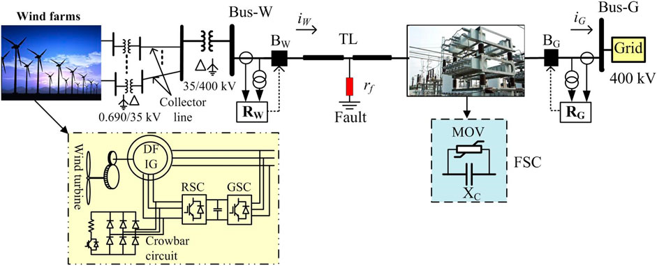
FIGURE 1. Single-line diagram of a two-bus test power system (in this study, the zone-1 reach of RW and RG is set equal to 80% length of the TL).
2.1 Impact study on wind farm-side relay RW
The wind farm is usually connected to the grid through a star-grounded HV transformer, as shown in Figure 1. As the wind farm side is delta connected, it restricts the flow of zero-sequence current when a ground fault occurs in the interconnected TL. The zero-sequence current of the ground fault is limited only by the zero-sequence impedance of the HV transformer and the TL. Thus, higher magnitudes of zero-sequence current than positive- and negative-sequence currents exist as the wind farm side acts as a weak power supply system. The unusual sequence components of current during ground fault and the control action of the DFIG-WTGs with LVRT capability affect the performance of wind farm-side distance relay RW.
To test the performance of relay RW of Figure 1 during ground faults, a cg-fault (rf = 10 Ω) is started at 1 s on the 400-kV line at a distance of 270 km (90% length of the line) from RW with a wind speed v = 15 m/s and an FSC compensation level (CL) = 40%. The result for the fault case is shown in Figure 2. As shown in Figure 2A, the magnitude and wave shape of phase-c current and the sequence currents produced are pretty unusual due to the grounding arrangements and control actions of the DFIG-WTGs. Due to the high magnitude of zero-sequence current and the limited increase in fault current magnitude of phase-c, the impedance ZW (=
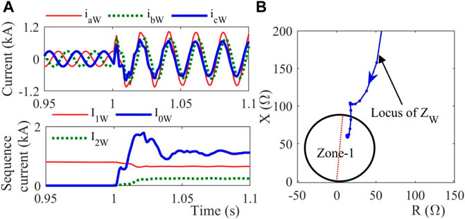
FIGURE 2. Demonstration of the impacts of unbalanced ground faults (cg-type) on relay RW protecting the large-scale DFIG wind farm-connected TL.
The apparent impedance ZW seen at relay RW (Figure 1) during a balanced three-phase fault can be computed as (Biswas and Nayak, 2021a)
where
To test the performance of RW, the result of a three-phase fault (rf = 5 Ω) started at a distance of 210 km (70% length of the TL) from RW with v = 15 m/s is shown in Figure 3. As observed in Figure 3A, during steady-state,
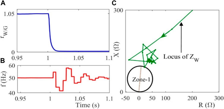
FIGURE 3. Demonstration of the impacts of three-phase faults on the performance relay RW protecting the large-scale DFIG wind farm-connected TL.
2.2 Impact study on grid-side relay RG
As in Figure 1, series compensation in the fault loop affects the apparent impedance measured by grid-side distance relay RG. The apparent impedance ZG measured at relay RG for different faults (abc/abcg, ag, and ab/bag types) when occurring at
In (2)–(4), the voltage drops across the FSC, i.e.,
To evaluate the performance of RG, the results of two typical fault cases are demonstrated here. The first one is a three-phase fault (abcg-type) created at 270 km (90%-line length) away from RG while v = 10 m/s and compensation levels are 40% and 70%, respectively. Results for the test cases are provided in Figure 4. It is evident from Figure 4A that the relay RG faces an overreach problem due to the presence of series compensation in the fault loop. Another ag-fault is created, keeping the fault distance and wind speed the same. The characteristics of the relay RG are shown in Figure 4B. In this fault case also, RG faces an overreaching problem.
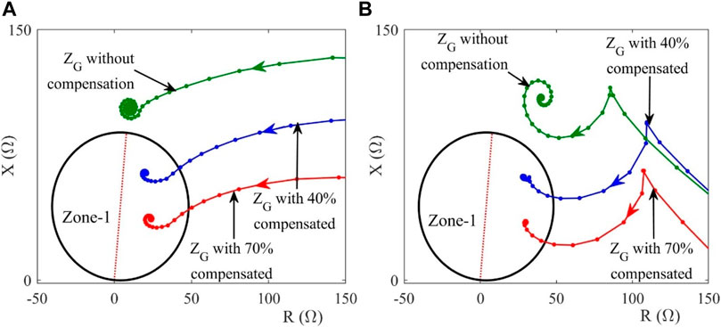
FIGURE 4. Demonstration of the impacts of balanced and unbalanced ground faults on relay RG during (A) abcg-fault and (B) ag-fault.
3 Proposed protection scheme
In the present work, signs of the half-cycle magnitude differences of the line end positive-sequence currents are utilized for discriminating internal faults from external faults. Furthermore, the currents measured at the utility grid side are processed through FBSE and the SVD, and finally, the BE classifier is used for fault classification. The calculation steps of the proposed fault detection and classification scheme are provided in the following sections in detail.
3.1 Proposed fault detection technique
Let the three-phase currents of the grid side and wind farm side be denoted as
where
where P represents the no. of samples/cycles.
It is observed from the simulation results that at the inception of an internal fault, there is a reduction in positive-sequence current magnitude from the wind farm side, whereas there is an increase in positive-sequence current magnitude from the grid side to the fault point. Consequently, the half-cycle magnitude differences of the positive-sequence current at the wind farm side become negative just after initiating an internal fault. On the other hand, the half-cycle magnitude differences of the positive-sequence current at the grid side become positive just after initiating an internal fault. As a result, the signs of
During steady-state system operating conditions,
Thus, the proposed fault detection unit (FDU) detects a fault when the criterion in (8) is satisfied.
Elimination of noise and subharmonics from the fault current signals using the Weiner filter
The use of anti-aliasing filters in DFT restricts the noise in the fault current signals. However, the DFT has a limitation in eliminating subharmonic components generated in the wind farm-side fault current due to the control actions of the DFIG. In this work, the Weiner filter removes subharmonics from the fault current (Tikhonov, 1963). Let an observed signal
Using Tikhonov regularization,
where
Here, the estimated signal
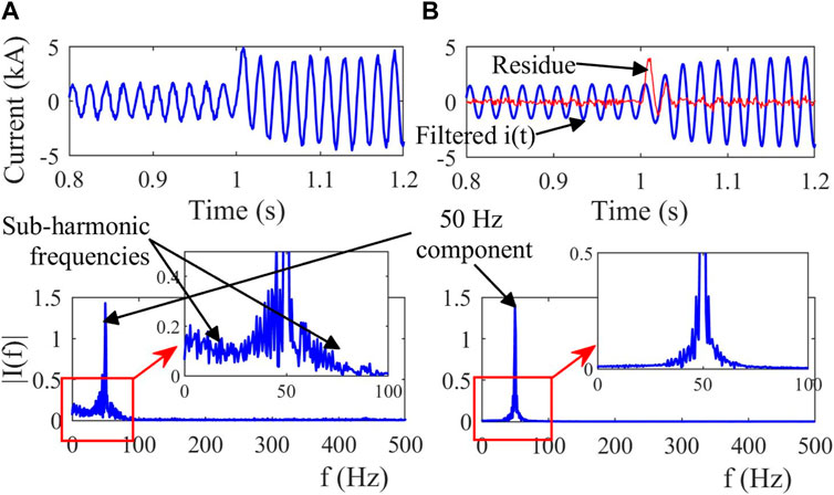
FIGURE 5. Demonstration of the elimination of subharmonic components from the contaminated fault current signal using the Weiner filter.
3.2 Proposed fault classification technique
The FBSE is an efficient time-frequency signal processing technique widely used to analyze non-linear and non-stationary signals. The main advantage of FBSE is that it has unique coefficients for a given signal, and the Bessel functions are aperiodic and decay over time (Pachori and Sircar, 2008). The synthesized signal from the FB coefficients has an inherent filtering property that helps reduce the noise in the low- and high-frequency regions of the spectrum. The various application areas of FBSE include speech-related applications (Gopalan, 2001), (Gopalan et al., 1997) and fault diagnosis studies (D’Elia et al., 2012), (Tran et al., 2013). In the fault diagnosis area, the FBSE and the Wigner–Ville distribution are used together to identify gear faults (D’Elia et al., 2012). Tran et al. (2013) used FBSE in association with generalized discriminant analysis and simplified fuzzy ARTMAP to diagnose induction motor faults. The mathematical backgrounds and the applicability of FBSE, SVD, and BE classifiers for TL fault classification are provided in the following.
3.3 Fourier–Bessel series expansion
As previously mentioned, the grid-side three-phase current signals are utilized for fault classification. Let the discrete-time-domain current signal of the grid side be denoted as
where
Using the orthogonality of the set
where
3.4 Singular value decomposition
Due to dimensionality issues, the direct use of FBSE coefficients as input feature vectors is computationally expensive. The SVD is an efficient matrix decomposition technique that can effectively reduce the vectors’ dimensionality and capture the transient present in the measured time-domain signal (Pazoki, 2018). The SVD rearranges the FBSE coefficient matrix
where
where the diagonal elements
In the present work, the FBSE coefficients calculated using (13) from the measured one-cycle local post-fault current signal are stored in the matrix
The variation of the amplitudes of fault feature
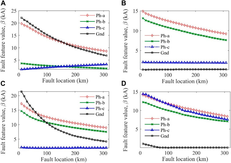
FIGURE 6. Demonstration of the variation of fault feature
3.5 Bagging ensemble classifier
An ensemble-based learning algorithm has drawn considerable attention in classification and regression problems in recent years. The idea behind this learning process is to use several learners instead of a single learner and aggregate them. It produces the final decision from the collective voting from the decision of the individual learners. The BE classifier is an ensemble classifier that uses the collaborative approach of the bagging and decision tree (DT). The BE classifier predictor is explicitly given as follows (Ho, 1995):
where
Here,
4 Results and discussion
The performance of the proposed protection scheme is tested on numerous possible fault cases (= 6000 cases) simulated on the two-bus system (Figure 1) by varying different parameters as listed in Table 1. The data are generated at a sampling frequency of 1 kHz. Results of some typical fault and non-fault cases are demonstrated in the following.
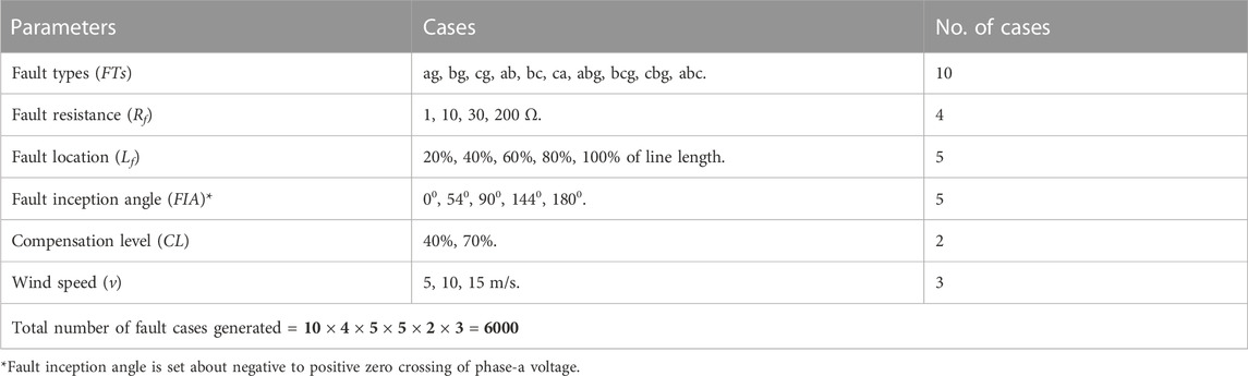
TABLE 1. Parameter variation for the generated 6000 possible fault cases.
4.1 Results of the proposed fault detection algorithm
4.1.1 Balanced fault
Results of a 3ph-fault initiated at 0.605 s with Lf= 240 km away from relay RG of Figure 1, FIA = 900, CL = 40%, and v = 10 m/s are shown in Figure 7. As seen in the figure, the half-cycle magnitude differences of the line end positive-sequence currents (
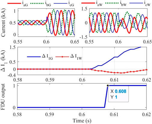
FIGURE 7. Result during a balanced 3ph-fault.
4.1.2 Unbalanced fault
Performance is demonstrated for two different unbalanced faults: 1) an ag-fault initiated at 0.6 s (Lf = 270 km (90% length of the line) away from RG with Rf = 10 Ω, FIA = 00, CL = 40%, and v = 5 m/s) and 2) a bc-fault initiated at 0.605 s (Lf = 210 km (70% length of the line) away from RG with FIA = 900, CL = 40%, and v = 15 m/s. Results of the previous three fault cases are shown in Figures 8A,B, respectively. It is evident from Figure 8A that for all the unbalanced fault cases, signs of
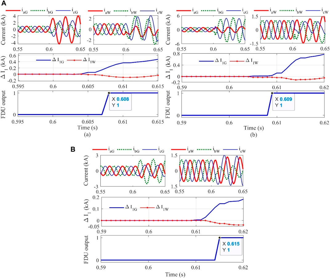
FIGURE 8. Results during (A) unbalanced fault, (a) ag-fault, (b) bc-fault and (B) high-resistance fault.
4.1.3 High-resistance fault
Fault detection during high fault resistance is often difficult due to the possibility of minimal changes in the current magnitude. To test the efficacy during such fault situations, a bg-fault is initiated at 0.61 s with Lf = 240 km away from RG, Rf = 200 Ω, FIA = 1800, CL = 70%, and v = 10 m/s. Despite high fault resistance, the signs of
4.1.4 Performance during three-phase fault producing current transformer saturation
Sometimes, the core of the CT is saturated due to severe short circuit faults and the burden settings of the CT. In such a situation, the secondary currents of the CTs may not be replicated correctly as those of the primary currents. Due to the incorrect secondary current during CT saturation, the relay may find difficulty in correctly distinguishing internal faults from external faults. To test the performance during such a situation, a three-phase fault is created at 0.603 s with Lf = 210 km (70% length of the line) away from RG while FIA = 540, CL = 40%, and v = 15 m/s. Here, the burden of grid-side CTs is chosen in such a way that the CT secondary current referred to as primary defers from the actual current, as shown in Figure 9A. The B-H curves of the three CTs shown in Figure 9B also confirm that the CT cores are saturated. Despite the CT saturation, the signs of the superimposed positive-sequence currents at Bus-G and Bus-W are opposite in polarity, and the proposed FDU detects and activates the FCU in 10 ms, considering 5 ms latency of PLCC. Thus, CT saturation is not an issue for the proposed fault detection algorithm.
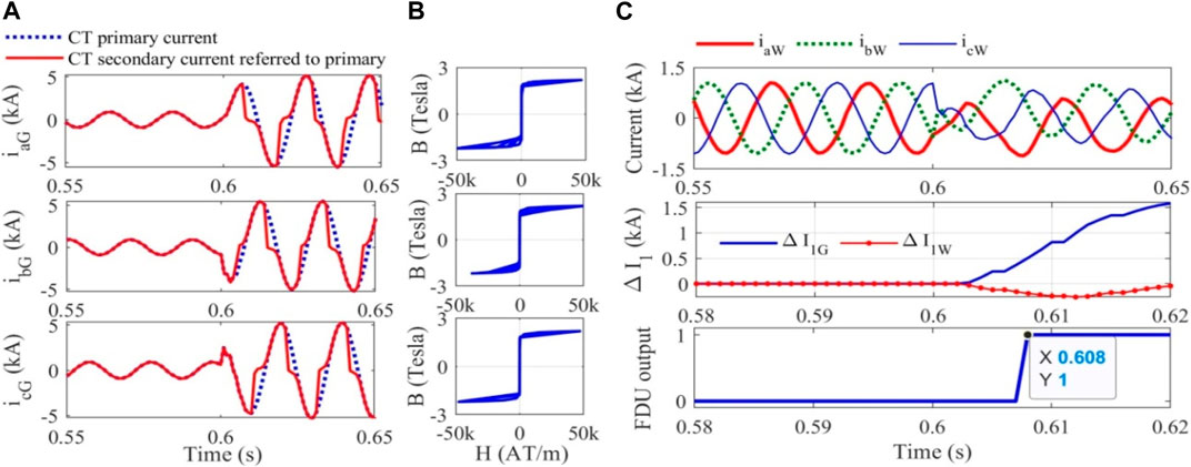
FIGURE 9. Performance of the proposed fault detection algorithm for faults producing CT saturation.
4.1.5 Non-fault transients
The fault detector should remain silent during non-fault transients such as capacitor switching, load switching, and noise. Results during the initiation of three non-fault transients: 1) switching of a capacitor equivalent to 40% MVAr capacity of the line, 2) a load of 50% capacity of the total MW demand is switched on suddenly, and 3) the presence of noise in the current waveform with a signal-to-noise ratio of 15 db. During the initiation of the previous three non-fault transients, the wind speed was maintained at 15 m/s. As observed from the results (Figures 10A–C), the present fault detection scheme remains silent during the initiation of all the three non-fault transients.
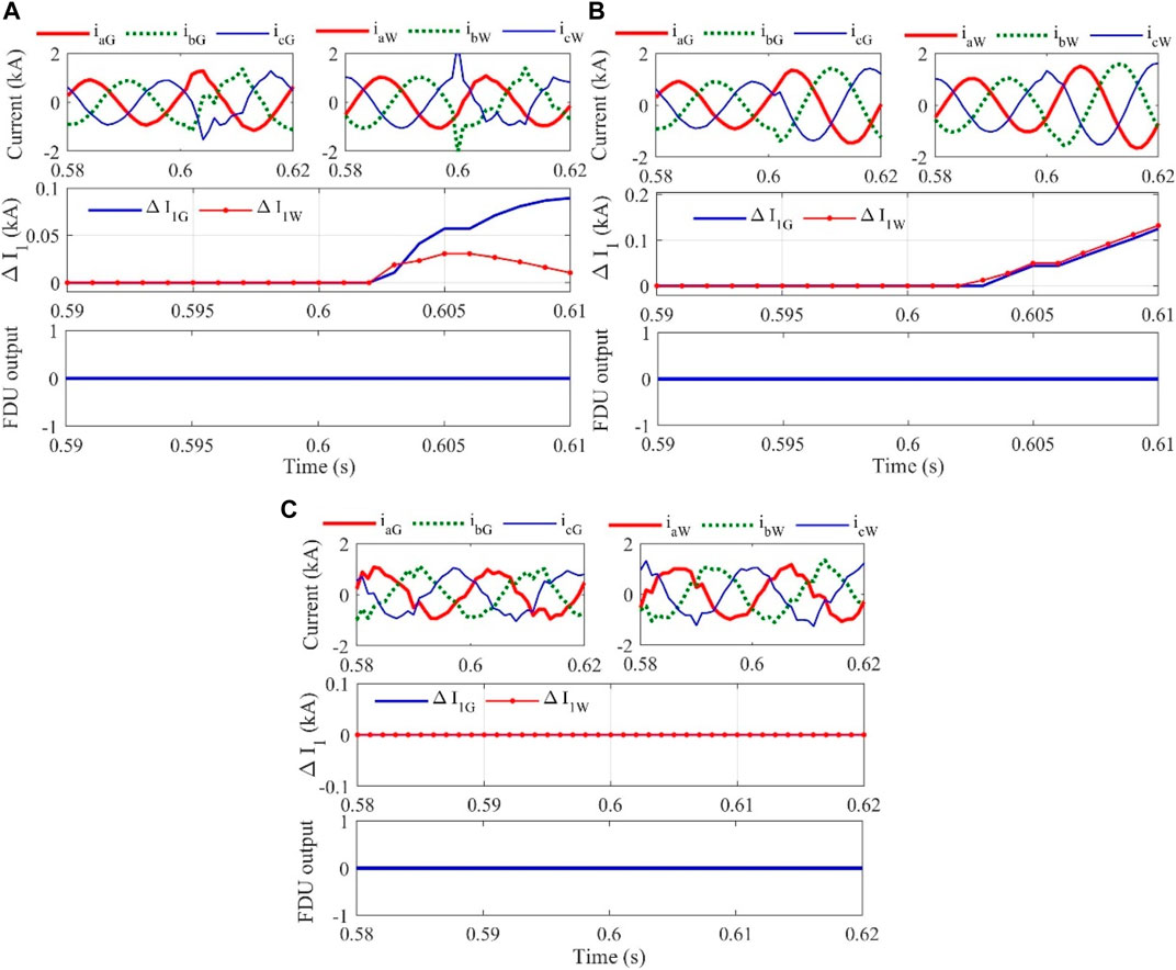
FIGURE 10. Results during switching transients: (A) capacitor switching, (B) load switching, and (C) presence of noise in the current signal.
4.2 Efficacy testing of the proposed fault classification scheme
The present work captures the current data for 6000 fault cases simulated in Figure 1 through MATLAB/Simulink® by changing the different parameters, as shown in Table 1. From the one-cycle post-fault three-phase current signals of all the generated fault cases, the valuable features are extracted using FBSE and SVD first. Out of the total generated data cases, 70% and 30% of the feature data cases are then used to train and test the BE classifier, respectively. The variations of the input fault feature
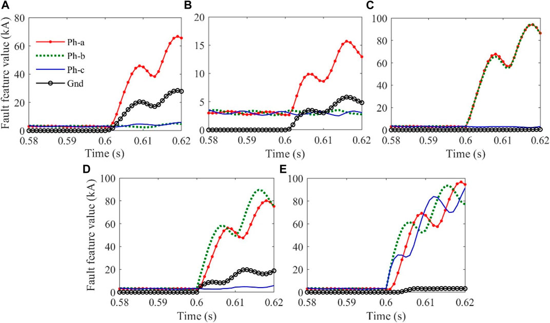
FIGURE 11. Demonstration of the variation of input fault features
The scatter plot of all the 6000-feature data generated, as demonstrated in Figure 12, clearly shows different feature datasets for different fault cases. The computed overall confusion matrix (Figure 13) shows that the classification accuracy of the proposed BE classifier for fault classification is 99.37%. Figure 14 shows the final tree structure of the BE classifier.
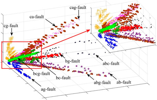
FIGURE 12. Distribution of input features for different fault cases.
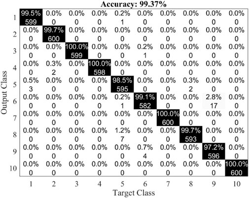
FIGURE 13. Overall confusion matrix of the BE classifier.
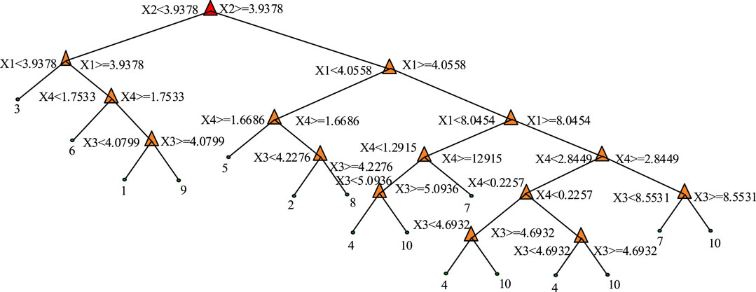
FIGURE 14. Final tree structure of the BE classifier.
In the present work, k-fold cross-validation is used to counteract the bias-variance problem. Here, the k-fold cross-validation uses k = 2, 5, 10, 15, and 20. As evident from Figure 15, after k = 5, there is no such improvement in the classification accuracy. Thus, to avoid computational complexity and time, fault classification accuracy is calculated using k = 5.
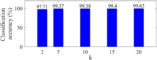
FIGURE 15. Variation of fault classification accuracies with k.
5 Comparative assessment
The performance of the proposed method is compared with Prasad et al. (2020), Mishra et al. (2019), Swetapadma et al. (2017), and Mohammad Taheri et al. (2018) earlier used for the protection of either FSC-compensated TLs or DFIG wind farm-connected TLs. The summarized comparative study considering different attributes is provided in Table 2. The table clearly shows that the proposed approach’s fault detection and classification accuracies are coming 100%. Similar accuracies are obtained earlier by Swetapadma et al. (2017) and Mohammad Taheri et al. (2018). However, the methods proposed by Swetapadma et al. (2017) and Mohammad Taheri et al. (2018) are tested only for FSC-compensated TLs. These protection schemes were not validated for large-scale DFIG wind farm integration. The control action of DFIG with LVRT capability and the grounding arrangement of DFIG produce unusual frequency components and unusual sequence currents, especially during ground faults. These characteristics will affect the performance of the existing methods.
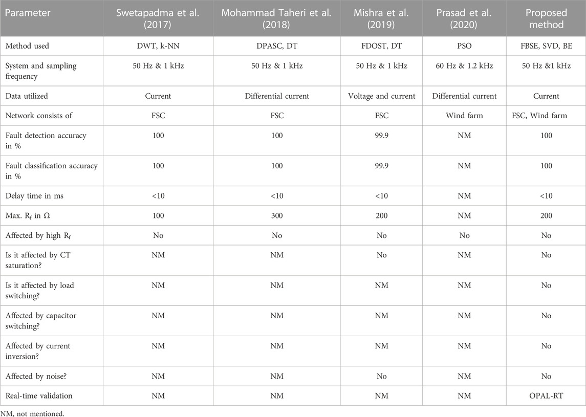
TABLE 2. Comparative assessment result.
Furthermore, the discrete wavelet transforms (DWTs), k-nearest neighbor (k-NN)-based method used in the study by Swetapadma et al. (2017), differential phase angle of superimposed current (DPASC), and DT-based method used in the study by Mohammad Taheri et al. (2018) are computationally not efficient compared to the proposed FBSE-SVD and BE classifier. Also, the methods proposed by Swetapadma et al. (2017) and Mohammad Taheri et al. (2018) have not been tested in the presence of non-fault transients such as significant load switching, switching on/off of capacitor banks, and CT saturation during severe short circuit faults. The method in the study by Mohammad Taheri et al. (2018) used the current differential principle. Such a scheme cannot ensure secure protection for TLs connecting large-scale DFIG wind farms. The performance of the proposed protection scheme has immunity to such non-fault transients. This shows that the overall performance of the proposed protection scheme is superior compared to that the existing approaches, mainly when used for the protection of FSC-compensated TLs connected with large-scale DFIG wind farms.
6 Real-time validation through the OPAL-RT platform
The proposed protection scheme is tested on the RTDS platform manufactured by OPAL-RT (OP4510. The experimental setup is shown in Figure 16A (Biswas et al., 2022). As shown in Figure 16B, the test model of Figure 1 is simulated in MATLAB/Simulink® and compiled in RT-Lab software. The real-time data are generated and stored in the processor of OP4510. The real-time current at the grid side for a 3ph-fault (Lf = 240 km from relay RG, CL = 70%, v = 5 m/s) provided in Figure 16C shows the fault detection and classification time of the proposed method is 20 ms. The real-time current at the wind farm site for the previous fault case is shown in Figure 16D. Considering 60 ms circuit breaker operating time, the faulted phases are finally tripped in 80 ms (Figures 16E,F). This shows that the proposed protection scheme can be implemented easily in real-time.
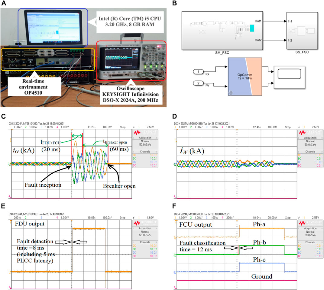
FIGURE 16. Results on the real-time environment: (A) real-time experimental setup, (B) Simulink in RT-LAB software, (C) grid-side current, (D) wind farm-side current, (E) FDU output, and (F) FCU output.
7 Conclusion
In the present paper, the limitations of distance relay protecting an FSC-compensated TL connecting large-capacity DFIG-WTGs are studied, and an intelligent protection scheme is proposed for fast and reliable detection and classification of faults in such crucial TLs. The proposed scheme utilizes the signs of the half-cycle magnitude differences of the line-end positive-sequence currents for fault detection, and the fault classification is performed using the local current measurements processed through the combination of the FBSE-SVD-BE classifier. Performance is evaluated on 6000 fault cases simulated on the two-bus test system through MATLAB/Simulink®. The method is also validated in OPAL-RT (OP4510) manufactured RTDS platform. The marginal computational burden, feasibility for real-time implementation, fast fault detection and classification time (<10 ms), 100% fault detection accuracies, and comparatively higher fault classification accuracies (= 99.37% are the main merits of the proposed relaying algorithm. However, the proposed approach’s efficacy is validated through the OPAL-RT-manufactured RTDS platform. It must be validated through the hardware-in-loop (HIL) experimental setup using OPAL-RT systems and field-programmable gate array (FPGA) boards with prototype relays and should be compared with existing relays used in fields such as SEL-421. This may be extended as future work.
Data availability statement
The original contributions presented in the study are included in the article/Supplementary Material; further inquiries can be directed to the corresponding author.
Author contributions
PM simulated the system and generated the data for training and testing the Fourier–Bessel series expansion (FBSE) bagging ensemble (BE) classifier for performing the fault classification task. He also wrote the initial draft of the manuscript. SB studied and tested the simultaneous impacts of the installation of series compensation and the integration of large-scale wind farms on distance relay performance. He also wrote the initial draft of Section 2 of the manuscript. PN edited the whole manuscript. AA provided guidence for the overall improvement of the manuscript. AS provided further guidence for the overall improvement of the manuscript.
Conflict of interest
The authors declare that the research was conducted in the absence of any commercial or financial relationships that could be construed as a potential conflict of interest.
Publisher’s note
All claims expressed in this article are solely those of the authors and do not necessarily represent those of their affiliated organizations, or those of the publisher, the editors, and the reviewers. Any product that may be evaluated in this article, or claim that may be made by its manufacturer, is not guaranteed or endorsed by the publisher.
References
Abdelaziz, A. Y., Ibrahim, A. M., Mansour, M. M., and Talaat, H. E. (2005). Modern approaches for protection of series compensated transmission lines. Electr. Power Syst. Res. 75 (1), 85–98. doi:10.1016/j.epsr.2004.10.016
Altuve, H. J., Mooney, J. B., and Alexander, G. E. (2009). “Advances in series-compensated line protection,” in 62nd Annual Conf. for Protective Relay Engineers, College Station, TX, USA, 30 March 2009 - 02 April 2009 (IEEE), 263–275.
Biswas, S., and Nayak, P. K. (2021). A fault detection and classification scheme for unified power flow controller compensated transmission lines connecting wind farms. IEEE Syst. J. 15 (1), 297–306. doi:10.1109/jsyst.2020.2964421
Biswas, S., and Nayak, P. K. (2019). An unblocking assistance to distance relays protecting TCSC compensated transmission lines during power swing. Int. Trans. Elect. Energy Syst. 29 (8), 1–21. doi:10.1002/2050-7038.12034
Biswas, S., and Nayak, P. K. (2021). A new approach for protecting TCSC compensated transmission lines connected to DFIG-based wind farm. IEEE Trans. Indus. Infor. 17 (8), 5282–5291. doi:10.1109/tii.2020.3029201
Biswas, S., Nayak, P. K., and Pradhan, G. (2022). A dual-time transform assisted intelligent relaying scheme for the STATCOM-compensated transmission line connecting wind farm. IEEE Syst. J. 16 (2), 2160–2171. doi:10.1109/jsyst.2021.3070448
Sahoo, B., and Samantaray, S. R. (2017). An enhanced fault detection and location estimation method for TCSC compensated line connecting wind farm. Int. J. Electr. Power Energy Syst. 96, 432–441. doi:10.1016/j.ijepes.2017.10.022
Central Electricity Regulatory Commission (2010). Indian electricity grid code. Available: http://cercind.gov.in/2010/ORDER/February2010/IEGC_Review_Proposal.pdf.
Chaurasiya, P. K., Warudkar, V., and Ahmed, S. (2019). Wind energy development and policy in India: A review. Energy Strategy Rev. 24, 342–357. doi:10.1016/j.esr.2019.04.010
Chen, S., Tai, N., Fan, C., Liu, J., and Hong, S. (2017). Adaptive distance protection for grounded fault of lines connected with doubly-fed induction generators. IET Gener. Transm. Distrib. 11 (6), 1513–1520. doi:10.1049/iet-gtd.2016.1145
Chen, S., Yin, X., and Zhang, Z. (2017). Impacts of DFIG-based wind farm integration on its tie line distance protection and countermeasures. IEEJ Trans. Electr. Electron. Eng. 12 (4), 553–564. doi:10.1002/tee.22411
Dash, P. K., Samantaray, S. R., and Panda, G. (2006). Fault classification and section identification of an advanced series-compensated transmission line using support vector machine. IEEE Trans. Power Deliv. 22 (1), 67–73. doi:10.1109/tpwrd.2006.876695
D’Elia, G., Delvecchio, S., and Dalpiaz, G. (2012). “On the use of Fourier-Bessel series expansion for gear diagnostics,” in Condition monitoring of machinery in non-stationary operations (Berlin, Germany: Springer), 267–275.
Dubey, R. K., Samantaray, S. R., and Panigrahi, B. K. (2014). Adaptive distance relaying scheme for transmission network connecting wind farms. Electr. Power Compon. Syst. 42 (11), 1181–1193. doi:10.1080/15325008.2014.921953
Fang, Y., Jia, K., Yang, Z., Li, Y., and Bi, T. (2018). Impact of inverter-interfaced renewable energy generators on distance protection and an improved scheme. IEEE Trans. Ind. Electron. 66 (9), 7078–7088. doi:10.1109/tie.2018.2873521
Fortescue, C. L. (1918). Method of symmetrical co-ordinates applied to the solution of polyphase networks. Trans. Am. Inst. Electr. Eng. 21 (2), 1027–1140. doi:10.1109/t-aiee.1918.4765570
Ghorbani, A., Mehrjerdi, H., and Al-Emadi, N. A. (2017). Distance-differential protection of transmission lines connected to wind farms. Int. J. Electr. Power Energy Syst. 89, 11–18. doi:10.1016/j.ijepes.2017.01.002
Gopalan, K., Anderson, T. R., and Cupples, E. J. (1997). “Speaker identification using features based on first-order Bessel function expansion of speech,” in IEEE Pacific Rim Conference on Communications, Computers and Signal Processing, 10 Years Networking the Pacific Rim, 1987-1997, Victoria, BC, Canada, 20-22 August 1997 (IEEE), 589–592.
Gopalan, K. (2001). “Speech coding using Fourier-Bessel expansion of speech signals,” in 27th Annual Conf. of the IEEE Indus. Electronics Society (Cat. No. 37243), Denver, CO, USA, 29 November 2001 - 02 December 2001 (IEEE), 2199–2203.
Ho, T. K. (1995). Random decision forests. in Proceedings of 3rd international conference on document analysis and recognition. Montreal, QC, Canada, 14-16 August 1995, IEEE, 278–282.
Hoang, T. T., Tran, Q. T., Le, H. S., Nguyen, H. N., and Duong, M. Q. (2022). “Impacts of high solar inverter integration on performance of FLIRS function: Case study for Danang distribution network,” in 2022 11th International Conference on Control, Automation and Information Sciences (ICCAIS) (Hanoi, Vietnam: IEEE), 327–332.
Hooshyar, A., Azzouz, M. A., and El-Saadany, E. F. (2014). Distance protection of lines connected to induction generator-based wind farms during balanced faults. IEEE Trans. Sustain. Energy 5 (4), 1193–1203. doi:10.1109/tste.2014.2336773
Hoq, M. T., Wang, J., and Taylor, N. (2021). Review of recent developments in distance protection of series capacitor compensated lines. Electr. Power Syst. Res. 190, 106831. doi:10.1016/j.epsr.2020.106831
Li, B., Liu, J., Wang, X., and Zhao, L. (2018). Fault studies and distance protection of transmission lines connected to DFIG-based wind farms. Appl. Sci. 8 (4), 562. doi:10.3390/app8040562
Lopez, J., Gubia, E., Sanchis, P., Roboam, X., and Marroyo, L. (2008). Wind turbines based on doubly fed induction generator under asymmetrical voltage dips. IEEE Trans. Energy Convers. 23 (1), 321–330. doi:10.1109/tec.2007.914317
Lopez, J., Sanchis, P., Roboam, X., and Marroyo, L. (2007). Dynamic behavior of the doubly-fed induction generator during three-phase voltage dips. IEEE Trans. Energy Convers. 22 (3), 709–717. doi:10.1109/tec.2006.878241
Ma, J., Zhang, W., Liu, J., and Thorp, J. S. (2018). A novel adaptive distance protection scheme for DFIG wind farm collector lines. Int. J. Electr. Power Energy Syst. 94, 234–244. doi:10.1016/j.ijepes.2017.07.008
Mishra, P. K., Yadav, A., and Pazoki, M. (2018). A novel fault classification scheme for series capacitor compensated transmission line based on bagged tree ensemble classifier. IEEE Access 6, 27373–27382. doi:10.1109/access.2018.2836401
Mishra, P. K., Yadav, A., and Pazoki, M. (2019). FDOST-based Fault Classification scheme for fixed series compensated transmission system. IEEE Syst. J. 13 (3), 3316–3325. doi:10.1109/jsyst.2018.2890288
Mishra, S., Gupta, S., and Yadav, A. (2021). A novel two-terminal fault location approach utilizing traveling-waves for series compensated line connected to wind farms. Elect. Power Syst. Res. 198, 107362. doi:10.1016/j.epsr.2021.107362
Mohamed, A. R., Sharaf, H. M., and Ibrahim, D. K. (2021). Enhancing distance protection of long transmission lines compensated with TCSC and connected with wind power. IEEE Access 9, 46717–46730. doi:10.1109/access.2021.3067701
Mohammad Taheri, M., Seyedi, H., Nojavan, M., Khoshbouy, M., and Ivatloo, B. M. (2018). High-speed decision tree-based series-compensated transmission lines protection using differential phase angle of superimposed current. IEEE Trans. Power Deliv. 33 (6), 3130–3138. doi:10.1109/tpwrd.2018.2861841
Nayak, P. K., Pradhan, A. K., and Bajpai, P. (2014). Wide-area measurement-based backup protection for power network with series compensation. IEEE Trans. Power Deliv. 29 (4), 1970–1977. doi:10.1109/tpwrd.2013.2294183
Nayak, S., Kar, S. K., Dash, S. S., Vishnuram, P., Thanikanti, S. B., and Nastasi, B. (2022). Enhanced salp swarm algorithm for multimodal optimization and fuzzy based grid frequency controller design. Energies 15 (9), 3210. doi:10.3390/en15093210
Novosel, D., Phadke, A., Saha, M. M., and Lindahl, S. (1997). “Problems and solutions for microprocessor protection of series compensated lines,” in Sixth International Conference on Developments in Power System Protection, Nottingham, UK, 25-27 March 1997 (IEEE), 18–23.
Ouyang, J., and Xiong, X. (2014). Dynamic behavior of the excitation circuit of a doubly-fed induction generator under a symmetrical voltage drop. Renew. Energy 71, 629–638. doi:10.1016/j.renene.2014.06.029
Pachori, R. B., and Sircar, P. (2008). EEG signal analysis using FB expansion and second-order linear TVAR process. Signal process. 88 (2), 415–420. doi:10.1016/j.sigpro.2007.07.022
Pazoki, M. (2018). A new fault classifier in transmission lines using intrinsic time decomposition. IEEE Trans. Ind. Inf. 14 (2), 619–628. doi:10.1109/tii.2017.2741721
Pradhan, A. K., and Joos, G. (2007). Adaptive distance relay setting for lines connecting wind farms. IEEE Trans. Energy Convers. 22 (1), 206–213. doi:10.1109/tec.2006.889621
Prasad, C. D., Biswal, M., and Abdelaziz, A. Y. (2020). Adaptive differential protection scheme for wind farm integrated power network. Electr. Power Syst. Res. 187, 106452. doi:10.1016/j.epsr.2020.106452
Prasad, C. D., and Biswal, M. (2020). Swarm intelligence-based differential protection scheme for wind integrated transmission system. Comput. Electr. Eng. 86, 106709. doi:10.1016/j.compeleceng.2020.106709
Sadeghi, H. (2012). A novel method for adaptive distance protection of transmission line connected to wind farms. Int. J. Electr. Power Energy Syst. 43 (1), 1376–1382. doi:10.1016/j.ijepes.2012.06.072
Schroeder, J. (1993). Signal processing via Fourier-Bessel series expansion. Digit. Signal Process. 3 (2), 112–124. doi:10.1006/dspr.1993.1016
Sivov, O., Abdelsalam, H., and Makram, E. (2016). Adaptive setting of distance relay for MOV-protected series compensated line considering wind power. Electr. Power Syst. Res. 137, 142–154. doi:10.1016/j.epsr.2016.03.048
Swetapadma, A., Mishra, P., Yadav, A., and Abdelaziz, A. Y. (2017). A non-unit protection scheme for double circuit series capacitor compensated transmission lines. Electr. Power Syst. Res. 148, 311–325. doi:10.1016/j.epsr.2017.04.002
Tikhonov, A. N. (1963). Solution of incorrectly formulated problems and the regularization method. Sov. Math. 4, 1035–1038.
Tran, V. T., Al Thobiani, F., Ball, A., and Choi, B.-K. (2013). An application to transient current signal-based induction motor fault diagnosis of Fourier–Bessel expansion and simplified fuzzy ARTMAP. Expert Syst. Appl. 40 (13), 5372–5384. doi:10.1016/j.eswa.2013.03.040
Varma, R. K., Auddy, S., and Semsedini, Y. (2008). Mitigation of subsynchronous resonance in a series-compensated wind farm using FACTS controllers. IEEE Trans. Power Del. 23 (3), 1645–1654. doi:10.1109/tpwrd.2008.917699
Varma, R. K., and Moharana, A. (2013). SSR in double-cage induction generator-based wind farm connected to series-compensated transmission line. IEEE Trans. Power Syst. 28 (3), 2573–2583. doi:10.1109/tpwrs.2013.2246841
Vishnuram, P., Ramachandiran, G., Sudhakar, T. B., and Nastasi, B. (2021). Induction heating in domestic cooking and industrial melting applications: A systematic review on modelling, converter topologies and control schemes. Energies 14 (20), 6634–34. doi:10.3390/en14206634
Vyas, B., Maheshwari, R. P., and Das, B. (2014). Protection of series compensated transmission line: Issues and state of art. Electr. Power Syst. Res. 107, 93–108. doi:10.1016/j.epsr.2013.09.017
Xiao, F., Zhang, Z., and Yin, X. (2015). Fault current characteristics of the DFIG under asymmetrical fault conditions. Energies 8 (10), 10971–10992. doi:10.3390/en81010971
Appendix
Parameters of the grid transmission line:
TL length: 300 km.
Positive-sequence impedance (Z1): 0.03293 + j0.327 Ω/km.
Zero-sequence impedance (Z0): 0.2587 + j1.1740 Ω/km.
Positive-sequence capacitive impedance: 280.1 MΩ/km.
Zero-sequence capacitive reactance: 461.2546 MΩ/km.
Parameters of DFIG wind farm:
Rating of wind farm: 0.690 kV, 50 Hz, 60 MW, 28 MVAr (40 Nos. × 2 MW each), slip = −0.25, and inertia constant: 4.32.
Collector lines: 30 km π-section, Z1 = 0.115 + j0.33 Ω/km.
Transformer before collector line Y/∆, 2.2 MVA, 0.690/35 kV, 50 Hz.
Transformer after collector line ∆/Y, 90 MVA, 35/400 kV, 50 Hz.
Parameters of the capacitor bank:
Capacitance: 80 μF (40% compensation), 45 μF (70% compensation); MOV voltage: 75 kV.
Keywords: series-compensated transmission line, DFIG-WTG, large-scale wind farm, distance relay, fault detection, fault classification, bagging ensemble classifier
Citation: Prabhu MS, Biswas S, Nayak PK, Abdelaziz A and El-Shahat A (2023) An intelligent protection scheme for series-compensated transmission lines connecting large-scale wind farms. Front. Energy Res. 11:1141235. doi: 10.3389/fenrg.2023.1141235
Received: 10 January 2023; Accepted: 06 March 2023;
Published: 24 March 2023.
Edited by:
Shiping Wen, University of Technology Sydney, AustraliaReviewed by:
Pradeep Vishnuram, SRM Institute of Science and Technology, IndiaMinh Quan Duong, The University of Danang, Vietnam
Nima Rezaei, Lakehead University, Canada
Copyright © 2023 Prabhu, Biswas, Nayak, Abdelaziz and El-Shahat. This is an open-access article distributed under the terms of the Creative Commons Attribution License (CC BY). The use, distribution or reproduction in other forums is permitted, provided the original author(s) and the copyright owner(s) are credited and that the original publication in this journal is cited, in accordance with accepted academic practice. No use, distribution or reproduction is permitted which does not comply with these terms.
*Correspondence: Paresh Kumar Nayak, cGFyZXNoQGlpdGlzbS5hYy5pbg==