 Fei Tang
 Yuhan Guo
 Xiaoqing Wei
 Mo Chen1,2
- 1School of Electrical Engineering and Automation, Wuhan University, Wuhan, China
- 2Hubei Engineering and Technology Research Center for AC/DC Intelligent Distribution Network, School of Electrical Engineering and Automation, Wuhan University, Wuhan, China
- 3State Grid Wuhu Power Supply Company, Wuhu, China
As the last defense line to avoid cascading failures, intentional controlled islanding (ICI) is of great significance to maintain the stability of power systems. However, with the increasing penetration of renewable energy, the system inertia and primary frequency regulation capacity have significantly decreased, and the adaptability and effectiveness of ICI have also been significantly reduced. Aiming at the above problems, an ICI strategy considering island frequency stability with wind-power integration is proposed. Firstly, a basic model of ICI is constructed through the collaborative optimization of load shedding, generator tripping, and the optimal intentional islanding boundary. Secondly, a frequency response model of the islanded system considering the primary frequency regulation of wind power is established, and the corresponding linear iterative algorithm is proposed. Finally, the established frequency stability constraints are embedded into the ICI model, forming a mixed integer linear program (MILP) model. The results and the effectiveness of islanding frequency control using the proposed strategy is discussed in the IEEE39 system compared with the traditional ICI strategy.
1 Introduction
Driven by the shortage of fossil energy, environmental pollution, and the pressure of carbon emissions, the penetration of renewable energy has been increasing (Breyer et al., 2022; Yang B et al., 2022; Xu et al., 2023). The large-scale grid connection of wind power brings new challenges to the safety and stability of the power system (Fang et al., 2022; Yang H et al., 2022). The dynamic characteristics of wind power units are significantly different from traditional synchronous generators, and the power system’s rotor angle stability characteristics have been profoundly changed (Agarala et al., 2022; Yadav and Saravanan, 2022). On the one hand, the opening space of traditional synchronous machines is occupied, and the system equivalent inertia is reduced, the risk of power system transient instability under large disturbances and extreme faults is correspondingly increasing (Tang et al., 2020; Tang et al., 2022). On the other hand, the primary frequency regulation capability of wind power units and their support to the grid is insufficient (Zhang et al., 2022).
Most of the current research on power system stability focuses on traditional power system. Traditional analysis methods including extended equal area criterion (EEAC), transient energy function and so on (Yang et al., 2006; Yan et al., 2011). In addition, artificial intelligence technology is also gradually being widely used (Fu et al., 2023). Yang conducts a pioneer study for SCUC problems that proposes an expanded sequence-to-sequence (E-Seq2Seq) based data-driven SCUC expert system for dynamic multiple-sequence mapping samples (Yang et al., 2021b). Yang further enhances its self-learning ability on the basis of data-driven method (Yang N et al., 2022a). However, the existing emergency control strategies are not effective enough with large-scale wind power integrated (Fotis et al., 2023; Al Masood et al., 2018). Considering the coexistence of traditional fault conditions and new network attacks during the operation of smart grid, it is urgent to propose some new power system stability control strategies (Zhang et al., 2023).
When a large disturbance triggers a transient instability of the system, through the timely implementation of ICI, the unstable system is separated into several disjoint, internally stable islands (Ding et al., 2017). At present, the research on the ICI problem mainly focuses on the appropriate time (when), the optimal boundary (where), and the execution method (how) three aspects (Ahangar et al., 2020). Since the location of the islanding boundary directly determines the stability characteristics of the islanded system, the “where” problem has become a popular research topic. According to the different objective functions in solving the optimal islanding boundary, the objective functions of the ICI strategy can be divided into: minimizing the unbalanced power of the islands, minimizing the power flow disruption, and other objective functions (Ahangar et al., 2020).
The unbalanced power can be expressed as the algebraic sum of the active power on the switched line, reflecting the frequency deviation of the islanded system (Qiao and Ma, 2022). The lower it is, the more beneficial to the recovery and economic operation of the islanded system (Jin et al., 2023). Sun proposes an ICI strategy based on the OBDD method, and verifies the effectiveness of controlled islanding with the minimum unbalanced power as the objective function (Sun et al., 2003). Xu proposes a three-stage ICI strategy based on graph theory with the same objective function. The solving efficiency is accelerated by determining the controlled islanding boundary through adaptive graph simplification, islanding cut-set search, and islanding scheme checking in turn (Xu and Miao, 2018). Kamali establishes a multi-objective function considering the unbalanced power and transient stability of the island, and an ICI strategy based on the MILP model is proposed to ensure the existence of steady-state operating points of the islanded system (Kamali et al., 2020).
The power flow disruption refers to the sum of the absolute values of the power on the disconnected branches, reflecting the effect of the ICI operation on the transient stability of the islanded system (Badal et al., 2019). Jian comprehensively considers the power flow on transmission lines and the electrical connection between nodes and defines the composite active power flow disruption. Then an ICI method is proposed based on a semi-supervised clustering algorithm to minimize the active power flow disruption (Jian et al., 2014). Isazadeh additionally considers the effect of reactive power flow disruption on the islanding stability, using the self-tuned online fuzzy factors. And weighted time-varying graph structure of the network is used to obtain islanding boundaries (Isazadeh et al., 2015).
With the increasing complexity of power system operation modes, new objective functions and constraints need to be established to guide the determination of islanding sections (Yang et al., 2021a). For example, Kyriacou pursues the reliability of power supply after ICI, and proposes an ICI method with the objective function of the maximum load-carrying capacity using the MILP model (Kyriacou et al., 2017). Ghamsari-Yazdel considers emerging regulation resources such as energy storage facilities and demand response, and establishes a comprehensive objective of minimizing controlling cost and dispatching costs (Ghamsari-Yazdel et al., 2020). Teymouri and Daniar focus on the frequency stability risk and the corresponding controlling cost after executing ICI in low-inertia power systems. Teymouri establishes an ICI strategy considering low-frequency load shedding control to reduce the controlling cost (Teymouri and Amraee, 2019). Daniar considers emergency load shedding control in ICI, which seeks to minimize load shedding while maintaining the system frequency (Daniar et al., 2021). However, the primary frequency control of wind power and the emergency load shedding control is not taken into consideration when the frequency increases (Li et al., 2023b).
In summary, the current research on ICI strategies is still focused on the power supply reliability and transient stability of the islanded system after executing ICI. The frequency stability characteristics of the islanded system and other emergency control strategies coordination are given less consideration (Zhu et al., 2022; Li et al., 2020). With the large-scale integration of wind power with weak frequency regulation capability, the equivalent inertia and primary frequency regulation capability of the islanding system will change significantly after ICI (Javadi et al., 2021; Yang N et al., 2022b). At this time, the unbalanced power generated by ICI may still exceed the maximum capacity of the islanding system, thus triggering multiple rounds of low-frequency load shedding or over-frequency generator tripping, even leading to frequency collapse (Li et al., 2023a).
In this paper, based on the traditional ICI model, the frequency stability constraints considering the participation of wind power in primary frequency modulation is added. First, the basic model of ICI is established. The islanding section, generator tripping, and load shedding are simultaneously taken as decision variables. The minimum generator tripping and load shedding is the goal. The generator coherency constraints, connectivity constraints, and other basic constraints are considered. At the same time, a frequency response model involving wind power is established, a linearized iterative solution algorithm is proposed, and the frequency stability constraints are formed. Finally, by embedding island frequency stability constraints, an ICI strategy considering island frequency stability is proposed, with practical significance and engineering value. The structure diagram of the modeling process is shown in Figure 1.
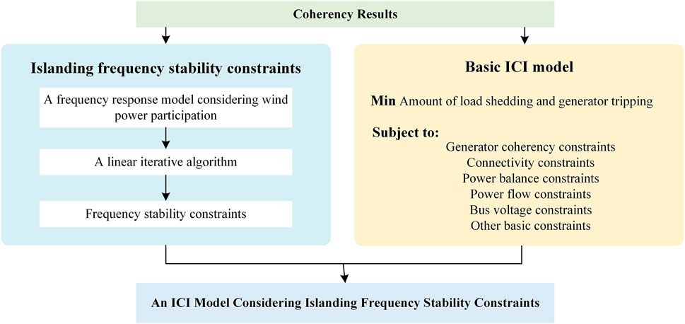
FIGURE 1. The structure of the ICI model considering frequency stability constraints.
The rest of this paper is organized as follows. In Section 2, the ICI model is constructed including the objective function, the basic constraints, and the method of constructing frequency stability constraint. Case studies and discussions based on the IEEE 39 system are shown in Section 3. The effectiveness of the proposed ICI strategy in maintaining frequency stability and the importance of wind power participation in frequency control are analyzed. Section 4 concludes this study by summarizing the key findings and contributions of this paper.
2 An ICI model considering islanding frequency stability constraints
2.1 Objective function
Since the frequency stability constraints have been considered in the proposed ICI model, it can be assumed that the unbalanced power generated by the execution of ICI will not collapse the island frequency. Therefore, to pursue lower controlling costs, the proposed ICI model takes the minimum load shedding as the objective function:
Where ΩL, ΩG, and Ωw are respectively a set of load nodes, synchronous generator nodes, and wind farm nodes. λL,i, λG,I, and λw,i are the penalty coefficients of shedding load i, tripping synchronizer i and wind farm i respectively. To comprehensively consider the influence of various control measures, the value of each penalty coefficient is set as 1.
2.2 Basic constraints
2.2.1 Generator coherency constraints
To ensure the transient stability of the islanding system, the nodes of the system should be assigned to different islands according to the generator coherency results. The transmission lines with nodes belonging to different islands on both sides should be disconnected (You et al., 2004). The generator coherency constraints are given by:
Where ΩN is the set of system nodes, ΩK is the set of isolated islands after ICI, and ΩB is the set of branches. Eq. 2 indicates that a node can only belong to an island. xi,k is a 0–1 variable, indicating that node i belongs to island k when xi,k = 1. Eq. 3 is used to judge the line switching state, and ai,j = 1 means the line is in normal operation. Since
2.2.2 Connectivity constraints
After executing the ICI method, all nodes in the island shall be connected to ensure there are no isolated nodes. A common connectivity constraint model is the single-commodity flow model (Ding et al., 2015), which assumes that there is only one virtual source node on the island, and that all other nodes carry a 1 pu virtual load. The balanced virtual power in the island indicates the inner connectivity of the island. The connectivity constraints based on the single-commodity flow model are given by:
Where,
2.2.3 Power balance constraints
The power balance of nodes must be ensured first after executing the ICI methods, as shown in Eq. 7.
Where,
2.2.4 Power flow constraints
To avoid the problem that the calculation result of DC power flow is not accurate enough, the AC power flow model is used in the constraints (Nan et al., 2018). The active and reactive power on a transmission line can be expressed as:
Where Vi, Vj is respectively the voltage amplitude of node i and node j at both ends of a line. δij is the phase angle difference of node i and node j after executing ICI. Gij, Bij, and
The linearized power flow constraints are given by (Kamali et al., 2020):
Where
2.2.5 Bus voltage amplitude and phase angle constraints
These constraints ensure that the voltage amplitude of each node and the voltage phase Angle difference between the two sides of the line are within the safety limit.
2.2.6 Other basic constraints
Where P, Q respectively represent the active power and reactive power of generators, while the superscript max and min represent the upper and lower limits of power value, the subscripts G,i and w,i respectively represent the synchronous generator i and wind farm i. Qw,i and φw,i are respectively the reactive power output and power factor of wind farm i. According to
2.3 Islanding frequency stability constraints
2.3.1 A frequency response model considering wind power participation
Based on the frequency response model, the frequency stability characteristics of the islanding system with wind power integrated during the ICI process (Javadi et al., 2021; Egido et al., 2009), as shown in Figure 2A. To simplify the analysis, the governor model of the synchronous generator is equivalent to a first-order inertial link, and non-linear links such as output limiting of the governor are retained.
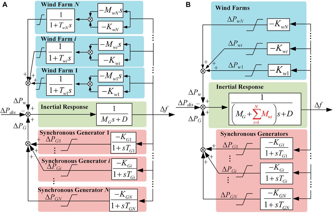
FIGURE 2. Frequency response model of isolated island system with wind power integrated, (A) is the frequency response model considering the dynamic of generators, (B) is the simplified frequency response model.
At the same time, virtual inertia control combined with droop control is selected as the primary frequency regulation strategy of wind power units.
In Figure 2, Twi is the time constant of primary frequency regulation, Mwi is the virtual inertial constant, Kwi is the droop control coefficient, MG is the total inertia of all operational synchronous generators in the system, D is the load damping coefficient, TGi is the governor time constant of synchronous generator i, KGi is the first frequency modulation coefficient, ΔPdis is the islanding unbalance power generated during ICI.
Considering that the response speed of the wind power unit is much higher than that of the synchronous machine under the converter control, the response delay of the wind power unit’s primary frequency regulation can be ignored. Therefore, TGi >> Twi≈0.
After equivalent aggregation of the inertia response of the synchronous generator and the virtual inertia control of the wind power unit, the total inertia of the system is given by:
The frequency response model of the system after simplified aggregation is shown in Figure 2B. Its dynamic equation is shown as:
Where, NG and Nw are respectively the number of synchronous generators and wind power units which are not tripped in the islanding system after executing ICI.
2.3.2 Islanding frequency stability constraints
Before establishing the islanding frequency stability constraints, the unbalanced power of the island must be solved first. The calculation process is shown as:
The load shedding condition is shown in Eq. 15, where
2.3.2.1 Maximum rate of change of frequency (ROCOF) constraints
At the moment of the ICI method execution, due to the frequency regulation dead zone and control delay, the primary frequency regulation control of the wind power units and the synchronous generators are started, and the islanding system can only rely on the inertia of the units to hinder the frequency change. At this time, the primary frequency regulation power ΔPGi(t) and ΔPwi(t) are 0, and the ROCOF reaches the maximum, as given by:
The maximum ROCOF constraints are shown as:
Where Msys,k is the system inertia of island k, as shown in Eq. 22. Tj,i and SG,i are respectively the inertial time constant and the unit capacity of the synchronous generator. Tw,i and Sw,i are respectively the virtual inertia time constant and the capacity of the wind power units. fN is the rated frequency of the system.
2.3.2.2 Transient frequency deviation constraints
Eq. 14 is discretized, and the time step between two adjacent discrete quantities is Δt (typical value is 0.05 s or 0.1 s),
Where Δfk,n is the frequency deviation of the island k relative to the frequency dead zone at number n step, ΔPGi,n and ΔPwi,n are the primary frequency regulation power of synchronous generator i and the droop control power of wind farm i at number n step respectively.
Since there is a nonlinear term of the multiplication of two variables in
When generators or wind farms are tripped, the respective auxiliary variable is equal to 0. Otherwise, when the generators and wind farms are normally operated, the respective auxiliary variable is equal to the product of unit inertia and frequency deviation.
Based on the above derivations, the linear expressions of
The primary frequency regulation power of the synchronous generator in Figure 2 can be discretized and modeled as:
Where, fdb,k is the frequency regulation dead zone of island k,
The linear expressions of
Where,
The droop control characteristics of wind farm are:
Where
After linearization, the wind farm i droop control power is shown as:
Where,
The frequency deviation curve of island k can be calculated by using
Where, Δfd,max and Δfd,min are respectively the upper and lower limits of the transient frequency deviation. In order to avoid triggering the low-frequency load shedding or over-frequency generator tripping, Δfd,max and Δfd,min are set at −0.75 Hz and 0.6 Hz respectively.
2.3.2.3 Quasi-steady state frequency deviation constraints
In the quasi-steady state stage, the frequency of the island system does not change, then
Where, Δfd,max is the quasi-steady state frequency deviation of island k, ΔPGi,s and ΔPwi,s are the droop control power of synchronous generator i and wind farm i in quasi-steady state stage respectively. The expressions are respectively given by:
The expressions after linearization with auxiliary variables are:
Where,
The quasi-steady state frequency deviation of island k can be calculated directly by combining
Considering the capacity of the island system after executing ICI may be small, the Δfs,min and Δfs,max are set as −0.5 Hz and 0.5 Hz respectively. The values of parameters are derived from the power system operation standards.
In summary, the proposed ICI model of wind power integrated system considering frequency stability constraints is a MILP model, which can be quickly solved in MATLAB by using commercial solvers such as GUROBI (Ringkjøb et al., 2018).
3 Simulations
Based on the modified IEEE39 system (Pai, 1989), the accuracy of the frequency response model proposed and its discretized linear iterative solution algorithm is verified. And the effectiveness of the proposed ICI model in maintaining the frequency stability of the islanding system is proved. The modified system model is shown in Figure 3. There are 14 generators and 50 lines in the system. The total load power is 6,097.1 MW, and the wind power penetration rate of the system reaches 44.2%. Synchronous generator G01 is not configured with a governor, G10 is configured with an IEEEG3 governor, and other synchronous machines are configured with an IEEEG1 governor. The relevant parameters are all typical values in DigSILENT software. All of the six wind farms participate in the primary frequency regulation control. During the simulation, the proposed frequency response discretization algorithm and the ICI model are solved in MATLAB by using the GUROBI solver, while the dynamic simulation is calculated by DigSILENT.
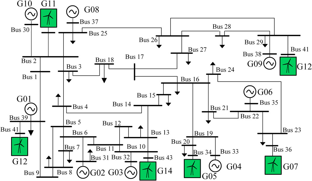
FIGURE 3. Modified IEEE-39 system topology.
3.1 Accuracy verification of discrete frequency response algorithm
First, a frequency step disturbance is applied to the speed control system of each synchronous generator, and then the step response of the governor is fitted with a first-order inertia link based on the least square method (Egido et al., 2009) to obtain the low-order model of each speed control system. The primary frequency regulation control parameters of the synchronous machine and the wind farm are shown in Table 1.
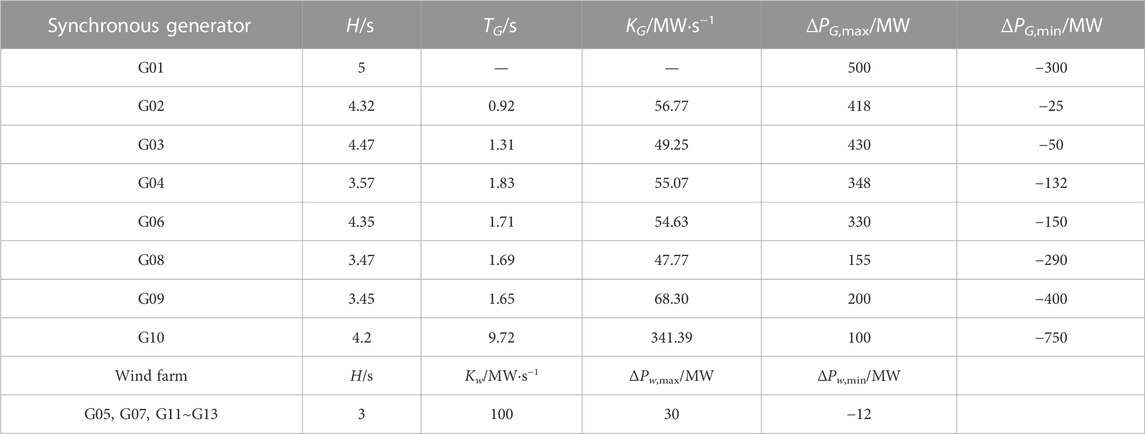
TABLE 1. Primary frequency regulation control parameters after low-order equivalence.
The following two disturbance cases are set to simulate some small disturbance scenarios such as load fluctuation and large disturbance scenarios such as line switch.
Case 1. The load on Bus3 generates a 50% power step increase to simulate small disturbances such as load fluctuations during normal operation.
Case 2. Line 1–39, line 3–4, and line 14–15 are tripped at t = 1 s, and the load on Bus4 generates a 50% power step decrease to simulate the large disturbance caused by stable control operations such as ICI and load shedding.
In order to verify the accuracy and effectiveness of the proposed frequency response solving algorithm, the frequency response curves in the two cases are calculated respectively based on the proposed discrete linear iterative algorithm and the time-domain simulation in DigSILENT. The results of the frequency response calculation are shown in Figure 4.
Figure 4A shows the frequency response curve of Case 1, where the calculation result of the proposed algorithm is shown by the dashed line, and the simulation results of the time domain are shown by the solid line. The amplification part shows the maximum frequency change rate of the system. According to the disturbance setting of Case 1, the system will generate a power shortage of 134.95 MW at t = 1 s. Therefore, at the initial disturbance stage, the maximum ROCOF is 0.105 Hz/s, which is slightly less than the average ROCOF obtained by the time domain simulation (0.118 Hz/s). In the stage of primary frequency regulation, according to the calculation results of the proposed frequency response algorithm, the lowest frequency of the system is 49.847 Hz, and the steady frequency is 49.894 Hz. Compared with the time-domain simulation results, the deviation is 0.003 Hz and 0.005 Hz respectively, and the relative error is 2.28% and 4.85%, meeting the 5% error of engineering application. The accuracy of the proposed frequency response model and its solving algorithm are verified in small disturbance scenarios.
Figure 4B shows the system frequency response curve of Case 2, where the calculation result of the proposed algorithm is shown by the dashed line, and the simulation result of the time domain is shown by the solid line. The amplification part shows the maximum frequency deviation between the frequency response curve and the time-domain simulation results. According to the disturbance setting of Case 2, the system is separated into two islands due to line switching. Island 1 contains {G01, G02, G03, G12, G14}, and the other generators are contained in island 2. In addition, island 1 has a power shortage of 141.15 MW, and island 2 has a power surplus of 425.33 MW. According to the calculation results of the proposed frequency response algorithm, the lowest frequency and steady frequency of island 1 are 49.211 Hz and 49.257 Hz respectively, while the lowest frequency and the steady frequency obtained by time domain simulation are both 49.235 Hz. The deviations are 0.024 Hz and 0.022 Hz, and the relative errors are 3.1% and 2.9% respectively, meeting the engineering application errors. In island 2, the frequency peak and steady state frequency calculated based on the proposed frequency response algorithm are 51.621 Hz and 50.688 Hz respectively, while the results obtained by time domain simulation are 51.564 Hz and 50.665 Hz respectively. Compared with the time-domain simulation results, the deviations of the lowest frequency and the steady-state frequency calculated based on the frequency response model are 0.057 Hz and 0.023 Hz respectively, and the relative error is 3.64% and 3.46% respectively, which meets the 5% error of engineering application. The accuracy of the proposed frequency response model and its solving algorithm are verified in large disturbance scenarios.
Based on the above analysis, the proposed discrete linear iterative algorithm for frequency response has relatively accurate calculation results in both small disturbance scenarios and large disturbance scenarios. The relative errors of transient frequency deviation, steady frequency deviation, and maximum ROCOF meet the requirements of engineering applications. The accuracy of the proposed algorithm is proved.
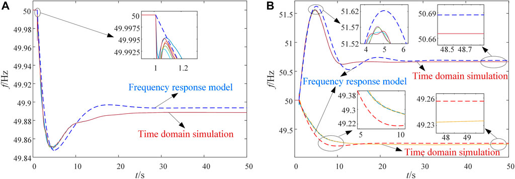
FIGURE 4. The frequency response curve result based on the proposed frequency response model and time domain simulation, (A) is the result according to Case 1, (B) is the result according to Case 2.
3.2 Validation of an ICI model considering island frequency stability
A three-phase fault is created on Bus3 at t = 1 s and the fault is removed at t = 1.6 s. After clearing the fault, the rotor angle of each unit (the wind farm is replaced by the voltage phase angle of the grid-connected bus) and the voltage curve of the grid-connected bus are shown in Figure 5.
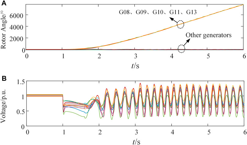
FIGURE 5. Dynamic response of the system after fault disturbance without executing controlled islanding, (A) is the rotor angle curve of generators, (B) is the voltage phase angle curve of grid-connected bus of each generator.
After the system is disturbed, the rotor angle of synchronous generators G08, G09, and G10, as well as the grid-connected bus voltage phase angle of wind farms G11 and G13 continue to increase. The bus voltage fluctuates periodically in a wide range and over 180° at t = 1.73 s. The system is unstable and separated into two groups {G08∼G11 and G13} (island 1) and {G1∼G7, G12 and G14} (island 2). It is necessary to implement the ICI method to separate the original system into two islands.
Four different ICI strategies are shown as follows:
Case 3. Regardless of the load shedding, generator tripping, and frequency stability constraints, the minimal unbalance power of the island is used as the objective function.
Case 4. Regardless of the load shedding operation and frequency stability constraints, the minimal power flow disruption is used as the objective function.
Case 5. Considering the load shedding, generator tripping, and frequency stability constraints, the primary frequency regulation control of wind power is not activated, and the minimal unbalance power of the island is used as the objective function.
Case 6. Based on Case 5, considering the primary frequency regulation control of the wind farm, and the minimal unbalance power of the island is used as the objective function. The virtual inertia time constant of all wind farms is 3 s, the droop control coefficient is 100 MW/Hz, and the upper and lower limits of active power change are ±30 MW.
The results of the four cases are shown in Table 2. The locations of the islanding sections are shown in Figure 6. Case 3 and Case 4 are the traditional ICI strategies aiming at minimum unbalanced power and minimum active power flow disruption, respectively. The islanding sections obtained in Case 3 and Case 4 are slightly different. In Case 3, five lines are tripped. The unbalanced power of island1 and island2 is 525.50 MW (surplus) and −474.32 MW (shortage), respectively, and the power flow disruption is 821.22 MW. In Case 4, four lines are tripped, the unbalanced power is the same as that in Case 3, and the power flow disruption is 817.36 MW.
The proposed ICI model is adopted in Case 5 and Case 6. The islanding section of Case 5 is similar to that of Case 3, with the exception of wind farm G11 being tripped and resulting in a load shedding of 366.43 MW. The unbalanced power of island 1 and 2 is reduced to 26.50 MW (surplus) and −107.89 MW (shortage), thus avoiding the instability of island frequency. However, Case 6 takes a step further by considering the primary frequency regulation of wind power on top of Case 5, resulting in only 241.27 MW load shedding in island 2, which is 125.16 MW less than what was observed in Case 5. Meanwhile, the unbalanced power of island 2 in Case 6 increases to 233.05 MW, which is 125.16 MW more than Case 5. The unbalanced power that each island can withstand is increasing, and the anti-disturbance ability is stronger when wind power participates in primary frequency regulation. Therefore, it is necessary for renewable energy units such as wind power to participate in the frequency control, which could improve the anti-disturbance ability of the system in the face of serious faults.
According to the islanding section results of Case 3 and Case 4 the dynamic response of the system calculated by DigSILENT are shown in Figure 7. Each island can maintain transient stability, and the bus voltage can return to normal quickly. Due to the existence of a large unbalance of power, the frequency of island 1 increases rapidly and is far higher than the safe upper limit of 50.6 Hz for a long time and cannot be recovered. Similarly, the frequency of islanding island 2 also continues to decrease due to the existence of power shortage, and remains near 48.9 Hz for a long time, which is far below the safe lower limit of transient frequency. Therefore, only optimizing the location of the islanding section can ensure the transient stability of the island system, but there is still the risk of frequency instability on each island.
The dynamic response of the system after executing ICI according to Case 5 and Case 6 is shown in Figure 8. The system also maintains transient stability and the node voltage quickly returns to normal value. However, different from Case 3 and Case 4, the frequency fluctuation of each island is within the limit value, and the frequency change speed and amplitude are much smaller. The steady-state frequency of Case 5 is about 49.52 Hz, and the steady-state frequency of Case 6 is about 49.51 Hz. Therefore, the effectiveness of the proposed ICI model in maintaining the frequency stability of the islanding system with wind power integrated is verified.
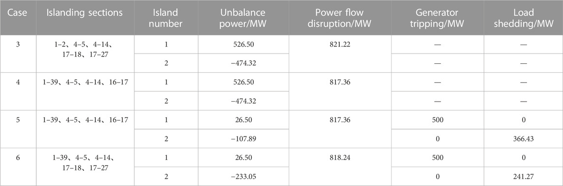
TABLE 2. Results of different intentional controlled islanding strategies.
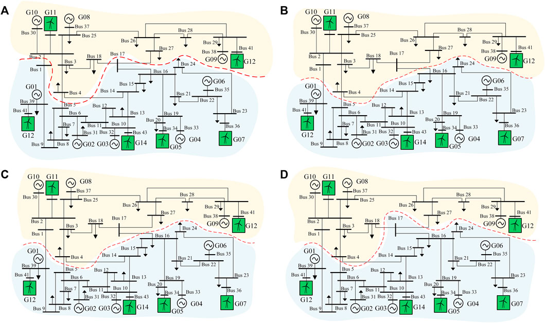
FIGURE 6. The locations of the islanding sections. (A–D) show the location of the islanding sections of Case 3–Case 6 respectively.
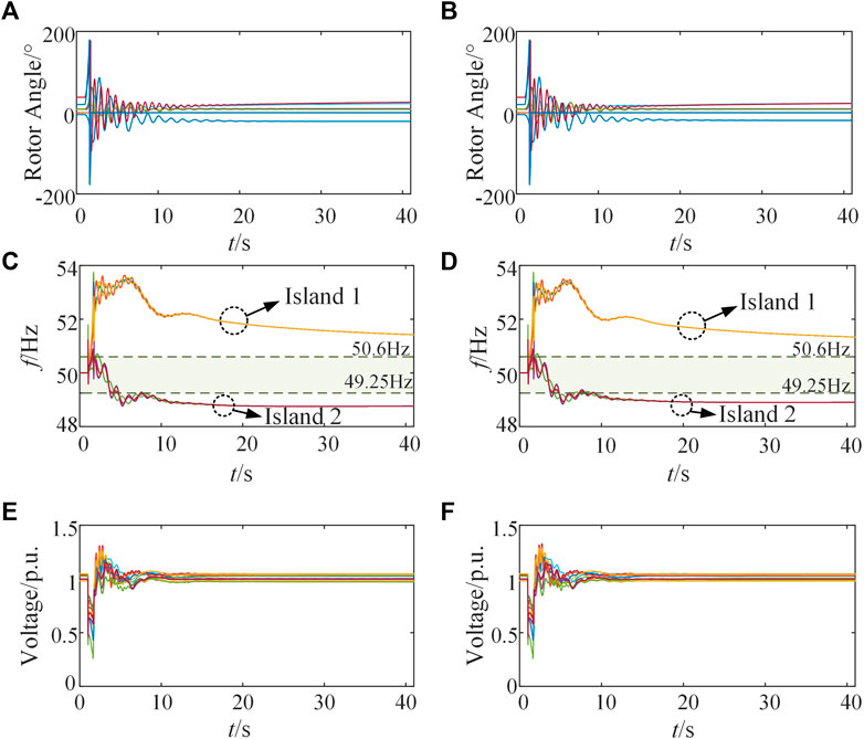
FIGURE 7. The dynamic response of the system after executing controlled islanding methods according to Case 3 and 4, (A) is the rotor angle curve of each generator in Case 3, (B) is the rotor angle curve of each generator in Case 4, (C) is the frequency curve of each island in Case 3, (D) is the frequency curve of each island in Case 4, (E) is the voltage curve of nodes in Case 3, (F) is the voltage curve of nodes in Case 4.
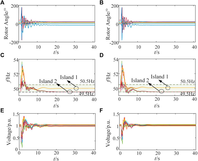
FIGURE 8. The dynamic response of the system after executing controlled islanding methods according to Case 5 and 6, (A) is the rotor angle curve of each generator in Case 5, (B) is the rotor angle curve of each generator in Case 6, (C) is the frequency curve of each island in Case 5, (D) is the frequency curve of each island in Case 6, (E) is the voltage curve of nodes in Case 5, (F) is the voltage curve of nodes in Case 6.
4 Conclusion
In this paper, a controlled islanding strategy considering frequency stability is proposed. The proposed model reduces the unbalanced power of islands and reduces the risk of frequency out-of-limit. It is beneficial to the safety and stability of isolated islands and improves the anti-disturbance ability of the power system with large-scale wind power integrated. The main conclusions are as follows:
1) Taking the load shedding, generator tripping, and islanding section as decision variables, the minimum amount of load shedding and generator tripping as the objective, the basic controlled islanding model is constructed. The coherency constraints, connectivity constraints, together with other basic constraints are taken into consideration.
2) A frequency response model of the island system considering wind power is established. And a linear iterative algorithm is proposed based on the idea of discrete modelling, from which the maximum ROCOF constraints, transient frequency deviation constraints, and quasi-steady state frequency deviation constraints are established. The simulation results show that when the system is subjected to small disturbances such as load fluctuation or large disturbances such as line disconnection, the linear iterative algorithm of the frequency response model proposed in this paper is close to the calculation results of the time domain simulation, and can satisfy the error of 5% in engineering application.
3) By embedding the frequency stability constraints, the controlled islanding MILP model for power systems with large-scale wind power integrated is formed. The modified IEEE 39 system simulation results show that compared with other methods, the proposed model can limit the frequency of each island to 49.5 Hz–50.5 Hz, and the load shedding is reduced by 125.16 MW. The unbalanced power that each island can withstand is increasing.
Data availability statement
The original contributions presented in the study are included in the article/supplementary material, further inquiries can be directed to the corresponding author.
Author contributions
FT was responsible for article construction article ideas, manuscript writing, simulation experiments, and data analysis. YG was responsible for review and supervision. XW and MC were responsible for organizing data and drawing figures. JS and HD were responsible for checking for errors and polishing the manuscript. All authors contributed to the article and approved the submitted version.
Funding
Project Supported by National Natural Science Foundation of China (NSFC) (NO. 51977157).
Conflict of interest
XW was employed by State Grid Wuhu Power Supply Company.
The remaining authors declare that the research was conducted in the absence of any commercial or financial relationships that could be construed as a potential conflict of interest.
Publisher’s note
All claims expressed in this article are solely those of the authors and do not necessarily represent those of their affiliated organizations, or those of the publisher, the editors and the reviewers. Any product that may be evaluated in this article, or claim that may be made by its manufacturer, is not guaranteed or endorsed by the publisher.
References
Agarala, A., Bhat, S. S., Mitra, A., Zychma, D., and Sowa, P. (2022). Transient stability analysis of a multi-machine power system integrated with renewables. Energies 15 (13), 4824. doi:10.3390/en15134824
Ahangar, A. R. H., Gharehpetian, G. B., and Baghaee, H. R. (2020). A review on intentional controlled islanding in smart power systems and generalized framework for ICI in microgrids. Int. J. Electr. Power & Energy Syst. 118, 105709. doi:10.1016/j.ijepes.2019.105709
Al Masood, N., Yan, R., and Saha, T. K. (2018). “Cascading contingencies in a renewable dominated power system: Risk of blackouts and its mitigation,” in 2018 IEEE power & energy society general meeting (PESGM), Portland, OR, USA, 05-10 Aug. 2018, 1–5. doi:10.1109/PESGM.2018.8586316
Badal, F. R., Das, P., Sarker, S. K., and Das, S. K. (2019). A survey on control issues in renewable energy integration and microgrid. Prot. Control Mod. Power Syst. 4, 8. doi:10.1186/s41601-019-0122-8
Breyer, C., Khalili, S., Bogdanov, D., Ram, M., Oyewo, A. S., Aghahosseini, A., et al. (2022). On the history and future of 100% renewable energy systems research. IEEE Access 10, 78176–78218. doi:10.1109/ACCESS.2022.3193402
Daniar, S., Aminifar, F., Hesamzadeh, M. R., and Lesani, H. (2021). Optimal controlled islanding considering frequency-arresting and frequency-stabilising constraints: A graph theory-assisted approach. IET Generation, Transm. Distribution 15 (14), 2044–2060. doi:10.1049/gtd2.12154
Ding, L., Guo, Y., and Wall, P. (2017). Performance and suitability assessment of controlled islanding methods for online WAMPAC application. Int. J. Electr. Power & Energy Syst. 84, 252–260. doi:10.1016/j.ijepes.2016.05.013
Ding, T., Sun, K., Huang, C., Bie, Z., and Li, F. (2015). Mixed-integer linear programming-based splitting strategies for power system islanding operation considering network connectivity. IEEE Syst. J. 12 (1), 350–359. doi:10.1109/JSYST.2015.2493880
Egido, I., Fernandez-Bernal, F., Centeno, P., and Rouco, L. (2009). Maximum frequency deviation calculation in small isolated power systems. IEEE Trans. Power Syst. 24 (4), 1731–1738. doi:10.1109/TPWRS.2009.2030399
Fang, P., Fu, W., Wang, K., Xiong, D., and Zhang, K. (2022). A compositive architecture coupling outlier correction, EWT, nonlinear Volterra multi-model fusion with multi-objective optimization for short-term wind speed forecasting. Appl. Energy 307, 118191. doi:10.1016/j.apenergy.2021.118191
Fotis, G., Vita, V., and Maris, T. I. (2023). Risks in the European transmission system and a novel restoration strategy for a power system after a major blackout. Appl. Sci. 13 (1), 83. doi:10.3390/app13010083
Fu, W., Jiang, X., Li, B., Tan, C., Chen, B., and Chen, X. (2023). Rolling bearing fault diagnosis based on 2D time-frequency images and data augmentation technique. Meas. Sci. Technol. 34 (4), 045005. doi:10.1088/1361-6501/acabdb
Ghamsari-Yazdel, M., Najafi, H. R., and Amjady, N. (2020). Incorporating energy storage and demand response into intentional controlled islanding using time decomposition. Int. Trans. Electr. Energy Syst. 30 (10), e12553. doi:10.1002/2050-7038.12553
Isazadeh, G., Khodabakhshian, A., and Gholipour, E. (2015). New intelligent controlled islanding scheme in large interconnected power systems. IET Generation, Transm. Distribution 9 (16), 2686–2696. doi:10.1049/iet-gtd.2015.0576
Javadi, M., Gong, Y., and Chung, C. Y. (2021). Frequency stability constrained microgrid scheduling considering seamless Islanding. IEEE Trans. Power Syst. 37 (1), 306–316. doi:10.1109/TPWRS.2021.3086844
Jian, Y., Fei, T., Qingfen, L., Yifei, W., and Enze, C. (2014). “Study on an optimal controlled islanding scheme based on active semi-supervised spectral clustering algorithm,” in 2014 International Conference on Power System Technology, Chengdu, China, 20-22 Oct. 2014, 48–54. doi:10.1109/POWERCON.2014.6993507
Jin, M., Zhu, X., and Zhou, J. (2023). Quantitative assessment of influence of renewable energy on peak regulation characteristics of power grid and its application. High. Volt. Appar. 04, 70–76. (in Chinese). doi:10.13296/j.1001-1609.hva.2023.04.010
Kamali, S., Amraee, T., and Fotuhi-Firuzabad, M. (2020). Controlled islanding for enhancing grid resilience against power system blackout. IEEE Trans. Power Deliv. 36 (4), 2386–2396. doi:10.1109/TPWRD.2020.3022967
Kyriacou, A., Demetriou, P., Panayiotou, C., and Kyriakides, E. (2017). Controlled islanding solution for large-scale power systems. IEEE Trans. Power Syst. 33 (2), 1591–1602. doi:10.1109/TPWRS.2017.2738326
Li, Z., Wu, L., Xu, Y., Wang, L., and Yang, N. (2023b). Distributed tri-layer risk-averse stochastic game approach for energy trading among multi-energy microgrids. Appl. Energy 331, 120282. doi:10.1016/j.apenergy.2022.120282
Li, Z., Xu, Y., Fang, S., Zheng, X., and Feng, X. (2020). Robust coordination of a hybrid AC/DC multi-energy ship microgrid with flexible voyage and thermal loads. IEEE Trans. Smart Grid 11 (4), 2782–2793. doi:10.1109/TSG.2020.2964831
Li, Z., Xu, Y., Wang, P., and Xiao, G. (2023a). Coordinated preparation and recovery of a post-disaster multi-energy distribution system considering thermal inertia and diverse uncertainties. Appl. Energy 336, 120736. doi:10.1016/j.apenergy.2023.120736
Nan, Y., Di, Y., Zheng, Z., Jiazhan, C., Daojun, C., and Xiaoming, W. (2018). Research on modelling and solution of stochastic SCUC under AC power flow constraints. IET Generation, Transm. Distribution 12 (15), 3618–3625. doi:10.1049/iet-gtd.2017.1845
Pai, A. (1989). Energy function analysis for power system stability. Berlin, Germany: Springer Science & Business Media.
Qiao, Z., and Ma, L. (2022). Research on large-scale energy storage control strategy for power system stability improvement. High. Volt. Appar. 12, 75–84+91. (in Chinese). doi:10.13296/j.1001-1609.hva.2022.12.012
Ringkjøb, H. K., Haugan, P. M., and Solbrekke, I. M. (2018). A review of modelling tools for energy and electricity systems with large shares of variable renewables. Renew. Sustain. Energy Rev. 96, 440–459. doi:10.1016/j.rser.2018.08.002
Sun, K., Zheng, D. Z., and Lu, Q. (2003). Splitting strategies for islanding operation of large-scale power systems using OBDD-based methods. IEEE Trans. Power Syst. 18 (2), 912–923. doi:10.1109/TPWRS.2003.810995
Tang, F., Liang, W., Wang, C., Gao, X., Hu, B., and Qin, F. (2020). Research on splitting optimization considering the planning of wind power integration. Sustainability 12 (18), 7726. doi:10.3390/su12187726
Tang, F., Wei, X., Guo, Y., Qi, J., Xie, J., and Li, X. (2022). Research on the unstable branch screening method for power system with high-proportion wind power. Front. Energy Res. 9, 835440. doi:10.3389/fenrg.2021.835440
Teymouri, F., and Amraee, T. (2019). An MILP formulation for controlled islanding coordinated with under frequeny load shedding plan. Electr. power Syst. Res. 171, 116–126. doi:10.1016/j.epsr.2019.02.009
Xu, P., Fu, W., Lu, Q., Zhang, S., Wang, R., and Meng, J. (2023). Stability analysis of hydro-turbine governing system with sloping ceiling tailrace tunnel and upstream surge tank considering nonlinear hydro-turbine characteristics. Renew. Energy 210, 556–574. doi:10.1016/j.renene.2023.04.028
Xu, S., and Miao, S. (2018). Three-stage method for intentional controlled islanding of power systems. J. Mod. Power Syst. Clean Energy 6 (4), 691–700. doi:10.1007/s40565-017-0348-2
Yadav, V. V., and Saravanan, B. (2022). Technical advances and stability analysis in wind-penetrated power generation systems—a review. Front. Energy Res. 10, 1091512. doi:10.3389/fenrg.2022.1091512
Yan, J., Liu, C., and Vaidya, U. (2011). PMU-based monitoring of rotor angle dynamics. IEEE Trans. Power Syst. 26 (4), 2125–2133. doi:10.1109/TPWRS.2011.2111465
Yang B, B., Liu, B., Zhou, H., Wang, J., Yao, W., Wu, S., et al. (2022). A critical survey of technologies of large offshore wind farm integration: Summary, advances, and perspectives. Prot. Control Mod. Power Syst. 7, 17. doi:10.1186/s41601-022-00239-w
Yang H, H., Chen, B., Xiang, S., Liu, J., and Ackom, E. (2022). Distributionally robust optimal dispatch modelling of renewable-dominated power system and implementation path for carbon peak. Comput. Industrial Eng. 163, 107797. doi:10.1016/j.cie.2021.107797
Yang, N., Dong, Z., Wu, L., Zhang, L., Shen, X., Chen, D., et al. (2021a). A comprehensive review of security-constrained unit commitment. J. Mod. Power Syst. Clean Energy 10 (3), 562–576. doi:10.35833/MPCE.2021.000255
Yang, N., Qin, T., Wu, L., Huang, Y., Huang, Y., Xing, C., et al. (2022a). A multi-agent game based joint planning approach for electricity-gas integrated energy systems considering wind power uncertainty. Electr. Power Syst. Res. 204, 107673. doi:10.1016/j.epsr.2021.107673
Yang, N., Yang, C., Wu, L., Shen, X., Jia, J., Li, Z., et al. (2021b). Intelligent data-driven decision-making method for dynamic multisequence: An E-seq2seq-based SCUC expert system. IEEE Trans. Industrial Inf. 18 (5), 3126–3137. doi:10.1109/TII.2021.3107406
Yang, N., Yang, C., Xing, C., Ye, D., Jia, J., Chen, D., et al. (2022b). Deep learning-based SCUC decision-making: An intelligent data-driven approach with self-learning capabilities. IET Generation, Transm. Distribution 16 (4), 629–640. doi:10.1049/gtd2.12315
Yang, W., Xue, Y., Sone, X., Wu, D., Ge, F., and Xie, D. (2006). “Study on stability mechanism for a typical fault with EEAC theory,” in 2006 International Conference on Power System Technology, Chongqing, China, 22-26 Oct. 2006, 1–4. doi:10.1109/ICPST.2006.321621
You, H., Vittal, V., and Wang, X. (2004). Slow coherency-based islanding. IEEE Trans. power Syst. 19 (1), 483–491. doi:10.1109/TPWRS.2003.818729
Zhang, Y., Wei, L., Fu, W., Chen, X., and Hu, S. (2023). Secondary frequency control strategy considering DoS attacks for MTDC system. Electr. Power Syst. Res. 214, 108888. doi:10.1016/j.epsr.2022.108888
Zhang, Y., Xie, X., Fu, W., Chen, X., Hu, S., Zhang, L., et al. (2022). An optimal combining attack strategy against economic dispatch of integrated energy system. IEEE Trans. Circuits Syst. II Express Briefs 70 (1), 246–250. doi:10.1109/TCSII.2022.3196931
Keywords: intentional controlled islanding, frequency stability, wind power, generation tripping, load shedding, generator coherency
Citation: Tang F, Guo Y, Wei X, Chen M, Sun J and Deng H (2023) An intentional controlled islanding strategy considering island frequency stability for power system with wind-power integrated. Front. Energy Res. 11:1247412. doi: 10.3389/fenrg.2023.1247412
Received: 26 June 2023; Accepted: 17 July 2023;
Published: 27 July 2023.
Edited by:
Zhengmao Li, Aalto University, FinlandReviewed by:
Yunyun Xie, Nanjing University of Science and Technology, ChinaLiang Yuan, Central South University, China
Copyright © 2023 Tang, Guo, Wei, Chen, Sun and Deng. This is an open-access article distributed under the terms of the Creative Commons Attribution License (CC BY). The use, distribution or reproduction in other forums is permitted, provided the original author(s) and the copyright owner(s) are credited and that the original publication in this journal is cited, in accordance with accepted academic practice. No use, distribution or reproduction is permitted which does not comply with these terms.
*Correspondence: Yuhan Guo, Z3VveXVoYW5Ad2h1LmVkdS5jbg==