 Maodong Shen1
 Yuqing Dong
 Kaiqi Sun
 Ke-jun Li
- 1School of Electrical Engineering, Shandong University, Jinan, China
- 2Department of Electrical Engineering and Computer Science, The University of Tennessee, Knoxville, TN, United States
With the increasing integration of distributed photovoltaic (PV) generation, the distribution network has met many challenges in operation and control. Ancillary services on PV generation systems become a necessary function to enhance the distribution network operating stability and resilience. However, due to the complexity of the control framework and the outer data dependency, the time delay on the measured data may bring a significant influence on the effectiveness of the PV system ancillary service. To solve the time delay influence, in this paper, a data-driven time-delay compensation strategy via the long short-term memory (LSTM) method is proposed. The proposed compensation strategy could realize the measured data compensation caused by the communication or calculation delay to maintain the accuracy of measured data that is input into the PV system ancillary service. Besides the LSTM-based method, the data-driven time-delay compensation strategy also includes a LSTM activation control to realize the smooth activation of the compensation strategy into the PV generation system. A modified IEEE 123 bus system with multiple distributed PV generation systems integration is conducted to verify the performance of the proposed compensation strategy. The simulation results indicate that the proposed data-driven time-delay compensation strategy could significantly improve the frequency performance of the PV ancillary service. In addition, the simulation results also show that the LSTM has a strong generalization ability for delay time constant and can deal with the random time delay caused by communication and disturbances in distribution systems.
1 Introduction
The booming development of distributed energy resources brings many opportunities in the power and energy field (Liang et al., 2023; Zhou et al., 2023). The power system is experiencing significant changes with the growth in renewable energy, and the development of the demand-side and energy storage (Sun et al., 2021b; 2023). Especially the rapid increase of renewable energies in the distribution network has challenged the traditional operation and control framework (Sun et al., 2021a).
In the conventional distribution network, the main component is load (Sun et al., 2022). In addition, the power transmission direction in the distribution network is fixed, which is from the transformer to the users. However, with the integration of distributed renewable energies into the distribution network, such as photovoltaic (PV) system integration, everything is changed (Raiker et al., 2021; Pranith et al., 2022). Due to most of the PV systems being connected to distribution networks, the composition of the distribution network is changed from mainly based on the load to the mix of load and generations (Ku et al., 2019; Zeraati et al., 2019). The largest change in the distribution network operation caused by the composition change is the power flow direction. Especially for the distribution networks with highly proportional PV system integration, the solar power generation from the PV system will continuously flow to the transformer and be sent to a high voltage level power system when the load demand in the distribution network is significantly insufficient. This phenomenon is called “backward power” and may cause many operation problems in protection devices, transformers, and other electric components because the design of these devices never considers this operation condition (Bellinaso et al., 2019).
To overcome these issues, the distribution system operators have developed many effective solutions. The most straightforward method for addressing these issues is to upgrade the existing conductors and distribution network transformers by replacing with larger ones. However, this method is expensive and may take a long time for construction. Some anti-backflow current facilities are also developed and have been equipped in the distribution network to prevent the occurrence of reverse power from the PV system. These advanced devices are effective, but they need to configure at a specific place to maximize the effect. However, the available place is precious in the distribution network, so it is difficult to satisfy all requirements. Therefore, the most economical method that may cover all the requirements is adding additional control to the PV system (Singh et al., 2022).
Much effective research has been conducted to provide additional control on the PV system (Jahan et al., 2021; Harag et al., 2022; Yang et al., 2022), which generally can be classified into voltage control (Varma and Salehi, 2017; Yi et al., 2018; Al-Saffar and Musilek, 2020; Wang et al., 2020; Zhang et al., 2022), and frequency control (Peng et al., 2020; Varma and Akbari, 2020; Li et al., 2021; Su et al., 2021). To enhance the PV system voltage stability, a multi-objective hierarchically coordinated VVC method with droop-controlled PV inverters is proposed to maximize benefits of the inverter-based voltage control in (Xu et al., 2022). In (Akagi et al., 2018), a comprehensive scheme to determine a suitable method and timing is proposed for upgrading the voltage control method. Voltage control methods are expected to be upgraded in accordance with the PV penetration in distribution systems. In (Callegari et al., 2021), a minimum dc-link voltage control for efficiency and reliability improvement of two-stage grid-connected PV inverters is proposed. In (Jain and Singh, 2017), a two-stage circuit topology is proposed, wherein the first stage is a boost converter, which serves for maximum power point tracking, and the second stage is a grid tied voltage source converter (VSC), which not only feeds extracted solar PV energy into the three-phase distribution system but also serves for harmonics mitigation, reactive power compensation, and grid current balancing. In (Karbouj et al., 2021), a self-adaptive voltage controller is proposed to enable solar PV power plant participation in voltage control ancillary service based on the reactive power capability estimation. In (Prasad et al., 2019), a method to optimize dc-link voltage of distribution static compensator based on load compensation requirement using reduced switch count multilevel converter integrated with PV system, which is capable of compensating reactive power, unbalance, and harmonics demanded by three-phase unbalanced and nonlinear loads connected to the distribution side, leading to improvement of power quality. In (Procopiou and Ochoa, 2017), a generic and practical remote voltage estimation method for the end points of low voltage feeders is proposed to substitute the need of remote monitoring without compromising performance and, hence, avoid the corresponding investment. For the frequency control (Li et al., 2021), proposes a novel sliding mode control based adaptive power point tracking control strategy to provide bi-directional primary frequency regulation of an AC microgrid. In (Quan et al., 2020), a novel ac coupled solution that transforms an existing grid-following PV system to a grid-forming one without any hardware and software modification of the PV inverter is proposed. In (Jampeethong and Khomfoi, 2020), a new coordination of electric vehicle (EV), wind farm, and photovoltaic for microgrid frequency regulation is proposed, where the proposed adaptive proportional integral (PI) controller is developed by using practical PI controllers. In (Li and Baran, 2020), a novel controller for large-scale PV plants is proposed, which uses a tracking linear quadratic regulator-based controller to help the system frequency effectively track that of a designed reference system with given inertia and droop constants. In (Hoke et al., 2017), a predictive PV inverter control method for very fast and accurate control of active power is proposed, which will increase the effectiveness of various higher-level controls designed to mitigate grid frequency contingency events, including fast power-frequency droop, inertia emulation, and fast frequency response, without the need for energy storage. In (Pandey et al., 2021), a robust frequency cascaded adaptive complex filter control for the grid interactive PV system is proposed.
However, the influence of time delay on the signal transmission loop has not been fully addressed in these control strategies. The phasor measurement unit (PMU) plays a more and more important role in PV control, where the time delay is inevitable resulting from the time consumption of the measurement, calculation, and communication. Additionally, the time delay may vary from tens to hundreds of milliseconds due to the various communication distance and performance of PMU. With the occurrence of time delay in the measurement process and the communication process between PMU and control center (Huang et al., 2016), the connected PV may bring destabilizing influence to the system. With the expansion of the distribution system, the conventional PV controller without considering communication time delay is inappropriate for distribution system with high penetration level. Most of the developed time delay compensation methods are based on known system models. While the actual system is under continuous adjustment with different types of generators and load put into the operation or retirement. The model-driven methods may have some limitation and is not appropriate for the current developing power system. For data-driven time delay compensation methods, Long Short-Term Memory (LSTM) networks offer significant advantages, especially when dealing with sequential data and time series analysis. Some key advantages of using LSTM networks includes: ability to handling long-term dependencies and sequential data, capability of capturing non-linear relationships, adaptability to changing patterns and dynamics, robustness to noise, and availability of pre-trained models (Sherstinsky, 2020).
With the aim of reducing the control deviation caused by time delay, a data-driven time-delay compensation strategy for PV controller is proposed. The main contributions of this manuscript includes.
(1) Establishment of rate of change of frequency (RoCoF) calculation block. To reduce the risk of system instability caused by the time delay, a RoCoF calculation block is established and deployed before the measured frequency signal goes into the frequency controller.
(2) Raise of the data-driven time-delay compensation strategy. Based on the Long Short-Term Memory (LSTM) network and the RoCoF calculation block, a data-driven time-delay compensation strategy for PV controller is proposed to correct the delayed frequency accurately.
(3) Comparison of the control performance. For comprehensive verification, the control effect of the proposed time-delay compensation strategy is tested in a PV integrated IEEE 123 bus system and compared with traditional Recurrent Neural Network (RNN) network.
2 Basic knowledge
The typical structure of a grid-connected photovoltaic power generation system is shown in Figure 1 (Mohammed Benaissa et al., 2017). The system includes solar array, DC/DC, DC/AC, transformer, AC load and other components. The photovoltaic arrays in the grid-connected photovoltaic power generation systems can convert solar energy into electrical energy and output direct current. After the DC voltage is boosted by the DC/DC converter, the DC/AC inverter converts the DC into AC. Through the control system, the AC output from the inverter can be controlled to have the same amplitude and frequency as the grid side. After passing through the transformer, the transmission of electric energy to the grid is realized.

FIGURE 1. Grid-connected photovoltaic power generation system.
The commonly used grid inverter control mode is the current control mode, which is composed with current closed-loop control to control the AC inductive current. At the same time, in order to control the DC voltage of the inverter, a voltage loop is added to control the DC voltage of the inverter, so the overall control strategy is the voltage and current double closed-loop control. Figure 2.
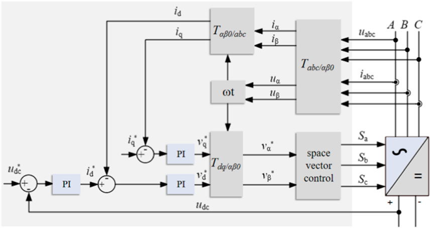
FIGURE 2. The double closed-loop control of the inverter.
As shown in Equations 1 and Eq. 2, and Eq. 3, the specific process of the double closed-loop control can be described as follows: The current ia, ib, ic and the voltage ua, ub, uc can be obtained from the power grid sampling. The voltage can be obtained from the DC side sampling. The voltage phase angle can be obtained from the grid voltage, by the
Considering the frequency drop after an event, it is necessary to use an appropriate controller to adjust the active power output of the PV to keep the system frequency at the nominal frequency, as shown in Figure 3. Targeting at frequency response control, the measured frequency is transmitted to calculate the frequency deviation. Passing through a PI control, the output will be added to the active power reference for power reallocation, so the system frequency can be gradually restored.
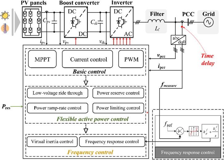
FIGURE 3. The time delay in the control system.
In the normal operation process, there will inevitably be corresponding communication delay and operation delay from voltage transformer, current transformer to data processor, resulting that the control of the grid-connected photovoltaic power generation system is not strictly real-time control. In this case, if such a long delay occurs in a distributed system, the operation of the system will be greatly impacted. In addition, due to the delay of system control, when the system is disturbed, the system cannot timely intervene the disturbance. In serious cases, the control behavior of the control system will even have the opposite result, reducing the stability of the system. Thus, a reliable time-delay compensation strategy is required in the PV penetrated system when providing ancillary frequency service.
3 Data-driven time-delay compensation strategy
The time delay compensation strategy is based on LSTM networks, which have a strong capability of dealing with time series data. This section will demonstrate the basic idea of LSTM network, and the establishment of the data-driven time-delay compensation strategy based on LSTM.
3.1 Preliminaries on LSTM
To improve the numerical instability of RNNs, several tricks such as new structure design are developed and implemented in the sophisticated sequence models. LSTM is one of the promising models that solves the problem of preserving the long-term information and skipping short-term input (She et al., 2022). Figure 4 shows the basic cell of LSTM. Apart from the typical input and output, the cell also includes a few gates recurrent units (GRUs), memory, candidate memory and hidden state. They are illustrated as follows.
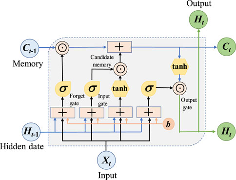
FIGURE 4. Basic cell of LSTM.
3.1.1 Gate recurrent units
There are three gate recurrent units utilized in LSTM: i). Input gate It is to decide whether to read data into the cell; ii). output gate Ot is responsible for reading out the entries from the cell; and iii). Forget gate Ft is designed for resetting the content of the cell. The hidden states and the input data are fed to the three units and processed by fully-connected layers with sigmoid activation functions. The output of the three GRUs are calculated as follows.
Where Wxi, Wxf, Wxo, Wni, Wnf, and Wno are weight parameters, and bi, bf, and bi are bias parameters.
3.1.2 Memory and candidate memory
LSTM can choose to remember or forget the information from the last time slot, leveraging the input gate and forget gate. First, candidate memory is generated using a tanh function as activation function.
where
Where
3.1.3 Hidden state
As shown in (13), hidden state Ht is calculated by integrating the current memory into the last hidden state. Ht belongs to [-1, 1] because it is processed by tanh before passed to the next cell.
With the special designs above, LSTM can finally capture the dependencies from historical data and predict the future value accurately.
3.2 Delay compensation strategy with LSTM
This subsection dives into the implementation of LSTM for delay compensation of frequency regulation of PV. Basically, the strategy can be split into two steps: the offline training and the online compensation. Details are demonstrated in the following subsections.
3.2.1 Offline training
As introduced in Section 3.1, the LSTM network is capable of predicting future data trend based on the historical data, so large sets of data need to be trained offline in advance. In the case of PV penetrated distribution system, various scenarios are simulated to feed the training, with different steady states and transient states. The steady state will cover different PV penetration and delay time constant, while the transient state will handle different load change amount and load change location. These scenario settings can cover most of the possibilities in the real world when the PV provides the frequency regulation under load variations, since severe contingencies will cause the PV to be cut off, in which case time delay can no longer take the major effect.
For each scenario, the Power System Computer Aided Design (PSCAD) performs the simulation and stores the PV bus frequency with and without time delay. The delayed bus frequency will be packaged as the input for the LSTM training, while the undelayed bus frequency will be the output.
3.2.2 Online compensation
After the offline training, the trained LSTM network is ready for the online compensation purpose. Figure 5 shows the overall structure of the time-delay compensation strategy. In a grid-tied PV system, the voltage and current are measured from the local PCC point. The PMU at the same bus collects the frequency magnitude as well as the phase angle. Typically, the time delay happens from the PMU to the frequency control inside the PV. With different disturbance types, the delay constant varies from dozens to hundreds of milliseconds. The trained LSTM is deployed before the measured frequency signal goes into the frequency controller so that the negative impact of the naturally-existed time delay can be reduced.
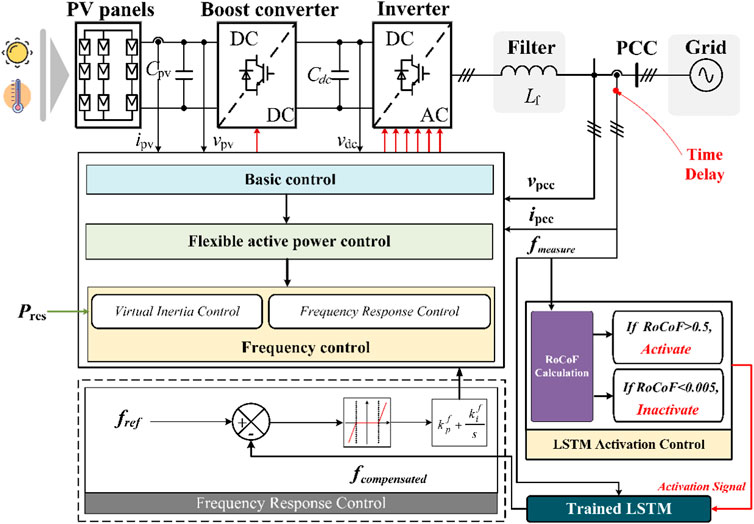
FIGURE 5. Time delay compensation strategy.
Considering the normal system conditions without any event, a threshold is designed to limit the redundant operation of the compensation control. An activation control is proposed to start or end the delay compensation strategy, which can be described in Eq. 8.
where RoCoF is the rate of change of frequency, which is the time derivative of the power system frequency, as shown in Eq. 9.
In the activation control, a RoCoF calculation block is equipped to receive the measured frequency and output the RoCoF value under same sampling rate. It is assumed that, when RoCoF is larger than 0.5 Hz/s, then the activation signal jumps to 1, indicating the LSTM compensation strategy is started. When RoCoF is smaller than 0.005 Hz/s, the activation signal becomes 0, which means the compensation block is deactivated. The starting and ending threshold avoid the frequent operation of the compensation block, since it is hard to predict the fluctuation of the frequency waveform under a normal system condition.
4 Case study
4.1 Model description
The IEEE 123 bus system is a widely used test model for research in distribution systems. As shown in Figure 6, the IEEE 123 bus system is divided into 5 sub-networks for location diversity. To observe the frequency response more clearly, the original voltage source connected to node 150 is replaced by a conventional generator. Two different buses are picked to be connected to the PV station: PV1 and PV2 are connected to node 151 and node 54 respectively. The modified IEEE 123 bus test model is established in PSCAD.
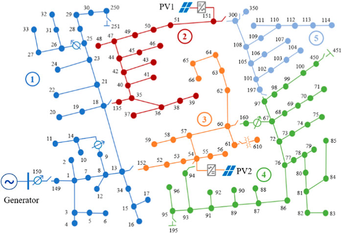
FIGURE 6. The topology of the modified IEEE 123 bus system.
4.2 LSTM training design
Before implementing the offline LSTM training, the dataset generation should be carefully designed to guarantee the sufficiency and comprehensiveness of the training data.
For each steady-state or transient-state variable, the training dataset is generated within certain range, listed in Table 1. Basically, ten points of each variable are picked as candidate training scenarios, so there are 1e4 groups of datasets in total. It is noted that for the two PV stations, the delay time in each PV may be same or different. If taking the delay time difference into account, there would be numerous possibilities. Therefore, it is critical to verify the generalization of the delay time constant, especially the different delay time constants in the two PVs of the untrained scenario.

TABLE 1. Datasets design.
The input of the LSTM is the delayed bus frequencies of PV1 and PV2, while the output of the LSTM is the original frequencies of the two PVs, which can be also considered as the expected compensated frequency signals.
After designing the training scenario and generating the datasets, the LSTM is conducted with the hyperparameters listed in Table 2. Then the well-trained LSTM can be applied in the compensation strategy in Figure 5 to predict and update the frequency signals in both PVs.
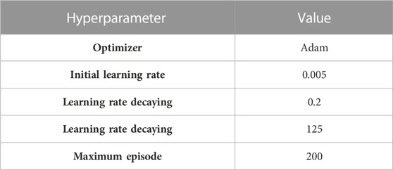
TABLE 2. LSTM hyperparameters.
4.3 Simulation results
To better validate the effectiveness of the LSTM base delay compensation strategy, two cases with different PV penetration, delay time constant, load change amount and load change location are designed in Table 3. The datasets for validation are distinguishable from the training datasets. In Case 1, the delay time constant is 100 m for both PV1 and PV2; while in Case 2, the delay time constant is 80 m for PV1 and 110 m for PV2. The two cases correspond to the trained (same time delay for each PV) and untrained (different time delay for each PV) scenarios, respectively.

TABLE 3. Validation cases.
The simulation results are compared with the traditional RNN network, which is the parent category of the LSTM network. Except the additional RoCoF calculation block as well as the LSTM activation control, all the input and output training data keep the same for RNN and the proposed time-delay compensation strategy.
Case 1. 1000 kW load increase at node 105 at t = 1s.
Figure 7 shows the dynamic response of the frequency signals at each PV station. The frequencies without delay, with delay and with two compensated strategies are compared in one diagram. From Figure 7, several observations can be carried out.
• The time delay degrades the performance of the frequency control from the following three aspects: 1) The frequency response delays 100 m for both two PVs when the contingency occurs; 2) Oscillation arises right after the load increase; 3) The frequency nadir is 0.004 Hz lower than the signal without delay for each PV.
• The frequency with the proposed compensated strategy can enhance the control effect with respect of both the starting period and the frequency nadir. When the frequency begins to drop after the load increase, the oscillation occurring in the delayed signal is diminished. In addition, the frequency nadir after the compensation is increased and very close to that of the frequency without delay. The frequency behavior indicates that the LSTM has a high prediction accuracy on the validating dataset.
• At the very beginning of the frequency drop, the compensated frequency is not fully tracked with the frequency without delay. Due to the LSTM activation control, the proposed delay compensation strategy will not be switched on until obvious RoCoF is detected. Therefore, the compensated frequency follows the delayed frequency for 100 m in both PVs. Based on this reason, the first cycle of frequency spike will be skipped since the duration of which is very short.
• Compared with the traditional RNN method, the proposed time-delay compensation strategy performs better to track the undelayed frequency signal in terms of the steady states and the key points, resulting from the LSTM activation control and the superior attributes of the LSTM network itself.
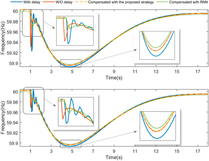
FIGURE 7. Frequency at PV1 and PV2 in case 1.
Case 2. 1200 kW load increase at node 18 at t = 1s.
Case 2 is designed under a bigger contingency, with a larger PV penetration (40%), a larger load increase amount (1200 kW), and an event location more adjacent to the generator. In addition, to verify the generalization of the different delay time constant in PV1 and PV2, the time delay in PV1 is 80 m and 110 m in PV2.
The dynamic response of frequency at each PV station is shown in Figure 8.
From Figure 8, the frequency without delay, with delay and with compensation are clearly compared. The following conclusions can be drawn in Case 2.
• With the different time delay in PV1 and PV2, the impact is still obvious but with some difference in the two PVs: 1) In PV1 (above), the delayed frequency lags 80 m to the frequency without delay; while in PV2 (below), the delayed frequency lags longer (110 m) than in PV1. 2) The nadir of the delayed frequency is 0.003 Hz lower than that of the frequency without delay at PV1; The nadir difference rises to 0.005 Hz at PV2. 3) In both PVs, the delayed frequency has oscillation after the load increase happens.
• Although the difference of delay time constant is not included in the training dataset, better performance can be achieved in both PV1 and PV2 when the delayed frequency is corrected with the compensation strategy. The oscillation at the contingency beginning period can be alleviated. The frequency nadir can be improved and close to that of frequency without delay.
• Similar drawbacks still exist regarding the first cycle of the frequency spike, which cannot be fully tracked by the compensated signal generated by the proposed compensation strategy. However, the frequency performance in the beginning and the nadir is still better compared to the RNN method.
To make the comparison more clearly, the compensation errors of the two methods are calculated according to (10) and listed in Table 4.
where CE is the compensation error. Fcom is the compensated frequency while fund is the undelayed frequency.
It can be concluded that the proposed time delay compensation strategy shows less error when predicting the undelayed frequency signal. Besides, the CE of Case 2 is larger than Case 1 for the following two reasons: the frequency deviates larger in Case 2 since the event is designed to be bigger; The scenario with different time delay constant in PV1 and PV2 is not trained, which may bring more error.
In general, the well-trained LSTM can provide accurate correction signals for frequency control. It has strong generalization ability for delay time constant, which is beneficial to its employment in real system. In addition, since LSTM method is inherently robust to noisy data, it can filter out noise and focus on the underlying patterns, which improves its feasibility for real-world data that often contains various sources of noise. With the delay compensator, the frequency control can address the random time delay and improve its control performance significantly.
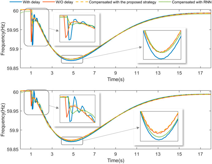
FIGURE 8. Frequency at PV1 and PV2 in case 2.
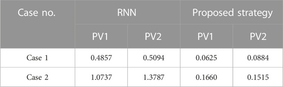
TABLE 4. Compensation error of each case.
5 Conclusion
In a modern distribution system with PV integration providing ancillary frequency regulation, the time delay issue in the measured frequency can degrade the performance of the frequency control in PV station and even results in instability. To address this issue, this paper further proposed a data-driven time-delay compensation strategy, which leverages an LSTM network and an LSTM activation control based on RoCoF calculation. The performance has been verified in a modified IEEE 123 bus system, and compared with traditional RNN network. In general, the proposed time-delay compensation strategy performs better to correct the delayed frequency signal in terms of the steady states and the key points, benefiting from the LSTM activation control and the superior attributes of the LSTM network. In addition, LSTM has a strong generalization ability for delay time constant and can deal with the random time delay caused by communication and disturbances in distribution systems. After employing the delay compensation approach, the performance of PV frequency regulation is improved significantly.
Data availability statement
The raw data supporting the conclusion of this article will be made available by the authors, without undue reservation.
Author contributions
MS: Conceptualization, Project administration, Writing–original draft. YD; Data curation, Methodology, Writing–original draft. KS: Funding acquisition, Investigation, Writing–original draft. K-JL: Supervision, Writing–review and editing.
Funding
The author(s) declare financial support was received for the research, authorship, and/or publication of this article. This work was supported by the Shandong Provincial Natural Science Foundation, China (ZR2022QE117).
Conflict of interest
The authors declare that the research was conducted in the absence of any commercial or financial relationships that could be construed as a potential conflict of interest.
Publisher’s note
All claims expressed in this article are solely those of the authors and do not necessarily represent those of their affiliated organizations, or those of the publisher, the editors and the reviewers. Any product that may be evaluated in this article, or claim that may be made by its manufacturer, is not guaranteed or endorsed by the publisher.
References
Akagi, S., Takahashi, R., Kaneko, A., Ito, M., Yoshinaga, J., Hayashi, Y., et al. (2018). Upgrading voltage control method based on photovoltaic penetration rate. IEEE Trans. Smart Grid 9, 3994–4003. doi:10.1109/TSG.2016.2645706
Al-Saffar, M., and Musilek, P. (2020). Reinforcement learning-based distributed BESS management for mitigating overvoltage issues in systems with high PV penetration. IEEE Trans. Smart Grid 11, 2980–2994. doi:10.1109/TSG.2020.2972208
Bellinaso, L. V., Figueira, H. H., Basquera, M. F., Vieira, R. P., Gründling, H. A., and Michels, L. (2019). Cascade control with adaptive voltage controller applied to photovoltaic boost converters. IEEE Trans. Industry Appl. 55, 1903–1912. doi:10.1109/TIA.2018.2884904
Callegari, J. M. S., Cupertino, A. F., Ferreira, V. de N., and Pereira, H. A. (2021). Minimum DC-link voltage control for efficiency and reliability improvement in PV inverters. IEEE Trans. Power Electron. 36, 5512–5520. doi:10.1109/TPEL.2020.3032040
Harag, N., Imanaka, M., Kurimoto, M., Sugimoto, S., Bevrani, H., and Kato, T. (2022). Autonomous dual active power-frequency control in power system with small-scale photovoltaic power generation. J. Mod. Power Syst. Clean Energy 10, 941–953. doi:10.35833/MPCE.2020.000700
Hoke, A. F., Shirazi, M., Chakraborty, S., Muljadi, E., and Maksimovic, D. (2017). Rapid active power control of photovoltaic systems for grid frequency support. IEEE J. Emerg. Sel. Top. Power Electron. 5, 1154–1163. doi:10.1109/JESTPE.2017.2669299
Huang, C., Li, F., Ding, T., Jiang, Y., Guo, J., and Liu, Y. (2016). A bounded model of the communication delay for system integrity protection schemes. IEEE Trans. Power Deliv. 31, 1921–1933. doi:10.1109/TPWRD.2016.2528281
Jahan, S., Biswas, S. P., Haq, S., Islam, Md. R., Mahmud, M. A. P., and Kouzani, A. Z. (2021). An advanced control scheme for voltage source inverter based grid-tied PV systems. IEEE Trans. Appl. Supercond. 31, 1–5. doi:10.1109/TASC.2021.3094446
Jain, C., and Singh, B. (2017). An adjustable DC link voltage-based control of multifunctional grid interfaced solar PV system. IEEE J. Emerg. Sel. Top. Power Electron. 5, 651–660. doi:10.1109/JESTPE.2016.2627533
Jampeethong, P., and Khomfoi, S. (2020). Coordinated control of electric vehicles and renewable energy sources for frequency regulation in microgrids. IEEE Access 8, 141967–141976. doi:10.1109/ACCESS.2020.3010276
Karbouj, H., Rather, Z. H., and Pal, B. C. (2021). Adaptive voltage control for large scale solar PV power plant considering real life factors. IEEE Trans. Sustain. Energy 12, 990–998. doi:10.1109/TSTE.2020.3029102
Ku, T.-T., Lin, C.-H., Chen, C.-S., and Hsu, C.-T. (2019). Coordination of transformer on-load tap changer and PV Smart inverters for voltage control of distribution feeders. IEEE Trans. Industry Appl. 55, 256–264. doi:10.1109/TIA.2018.2870578
Li, Q., and Baran, M. E. (2020). A novel frequency support control method for PV plants using tracking LQR. IEEE Trans. Sustain. Energy 11, 2263–2273. doi:10.1109/TSTE.2019.2953684
Li, Z., Cheng, Z., Si, J., Zhang, S., Dong, L., Li, S., et al. (2021). Adaptive power point tracking control of PV system for primary frequency regulation of AC microgrid with high PV integration. IEEE Trans. Power Syst. 36, 3129–3141. doi:10.1109/TPWRS.2021.3049616
Liang, Y., Ding, Z., Zhao, T., and Lee, W.-J. (2023). Real-time operation management for battery swapping-charging system via multi-agent deep reinforcement learning. IEEE Trans. Smart Grid 14, 559–571. doi:10.1109/TSG.2022.3186931
Mohammed Benaissa, O., Hadjeri, S., and Zidi, S. A. (2017). Modeling and simulation of grid connected PV generation system using matlab/simulink. IJPEDS 8, 392. doi:10.11591/ijpeds.v8.i1.pp392-401
Pandey, S. K., Kumar, S., and Singh, B. (2021). Robust frequency cascaded adaptive complex filter control for grid interactive PV system. IEEE Trans. Industry Appl. 57, 130–138. doi:10.1109/TIA.2020.3034285
Peng, Q., Yang, Y., Liu, T., and Blaabjerg, F. (2020). Coordination of virtual inertia control and frequency damping in PV systems for optimal frequency support. CPSS Trans. Power Electron. Appl. 5, 305–316. doi:10.24295/CPSSTPEA.2020.00025
Pranith, S., Kumar, S., Singh, B., and Bhatti, T. S. (2022). Improved Gaussian filter based solar PV-bes microgrid with PLL based islanding detection and seamless transfer control. IEEE Trans. Industrial Electron. 69, 5815–5825. doi:10.1109/TIE.2021.3088365
Prasad, K. K., Myneni, H., and Kumar, G. S. (2019). Power quality improvement and PV power injection by DSTATCOM with variable DC link voltage control from RSC-MLC. IEEE Trans. Sustain. Energy 10, 876–885. doi:10.1109/TSTE.2018.2853192
Procopiou, A. T., and Ochoa, L. F. (2017). Voltage control in PV-rich LV networks without remote monitoring. IEEE Trans. Power Syst. 32, 1224–1236. doi:10.1109/TPWRS.2016.2591063
Quan, X., Yu, R., Zhao, X., Lei, Y., Chen, T., Li, C., et al. (2020). Photovoltaic synchronous generator: architecture and control strategy for a grid-forming PV energy system. IEEE J. Emerg. Sel. Top. Power Electron. 8, 936–948. doi:10.1109/JESTPE.2019.2953178
Raiker, G. A., Loganathan, U., and Reddy, B. S. (2021). Current control of boost converter for PV interface with momentum-based perturb and observe MPPT. IEEE Trans. Industry Appl. 57, 4071–4079. doi:10.1109/TIA.2021.3081519
She, B., Dong, Y., and Liu, Y. (2022). Time delay of wide area damping control in urban power grid: model-based analysis and data-driven compensation. Front. Energy Res. 10. doi:10.3389/fenrg.2022.895163
Sherstinsky, A. (2020). Fundamentals of recurrent neural network (RNN) and long short-term memory (LSTM) network. Phys. D. Nonlinear Phenom. 404, 132306. doi:10.1016/j.physd.2019.132306
Singh, Y., Singh, B., and Mishra, S. (2022). Control of single-phase distributed PV-battery microgrid for smooth mode transition with improved power quality. IEEE Trans. Industry Appl. 58, 6286–6296. doi:10.1109/TIA.2022.3178388
Su, Y., Li, H., Cui, Y., You, S., Ma, Y., Wang, J., et al. (2021). An adaptive PV frequency control strategy based on real-time inertia estimation. IEEE Trans. Smart Grid 12, 2355–2364. doi:10.1109/TSG.2020.3045626
Sun, K., Li, K.-J., Zhang, Z., Liang, Y., Liu, Z., and Lee, W.-J. (2022). An integration scheme of renewable energies, hydrogen plant, and logistics center in the suburban power grid. IEEE Trans. Industry Appl. 58, 2771–2779. doi:10.1109/TIA.2021.3111842
Sun, K., Qiu, W., Dong, Y., Zhang, C., Yin, H., Yao, W., et al. (2023). WAMS-based HVDC damping control for cyber attack defense. IEEE Trans. Power Syst. 38, 702–713. doi:10.1109/TPWRS.2022.3168078
Sun, K., Qiu, W., Yao, W., You, S., Yin, H., and Liu, Y. (2021a). Frequency injection based HVDC attack-defense control via squeeze-excitation double CNN. IEEE Trans. Power Syst. 36, 5305–5316. doi:10.1109/TPWRS.2021.3078770
Sun, K., Xiao, H., Pan, J., and Liu, Y. (2021b). VSC-HVDC interties for urban power grid enhancement. IEEE Trans. Power Syst. 36, 4745–4753. doi:10.1109/TPWRS.2021.3067199
Varma, R. K., and Akbari, M. (2020). Simultaneous fast frequency control and power oscillation damping by utilizing PV solar system as PV-STATCOM. IEEE Trans. Sustain. Energy 11, 415–425. doi:10.1109/TSTE.2019.2892943
Varma, R. K., and Salehi, R. (2017). SSR mitigation with a new control of PV solar farm as STATCOM (PV-STATCOM). IEEE Trans. Sustain. Energy 8, 1473–1483. doi:10.1109/TSTE.2017.2691279
Wang, Y., Zhao, T., Ju, C., Xu, Y., and Wang, P. (2020). Two-level distributed volt/var control using aggregated PV inverters in distribution networks. IEEE Trans. Power Deliv. 35, 1844–1855. doi:10.1109/TPWRD.2019.2955506
Xu, R., Zhang, C., Xu, Y., Dong, Z., and Zhang, R. (2022). Multi-objective hierarchically-coordinated volt/var control for active distribution networks with droop-controlled PV inverters. IEEE Trans. Smart Grid 13, 998–1011. doi:10.1109/TSG.2021.3126761
Yang, J., Tushar, W., Saha, T. K., Alam, M. R., and Li, Y. (2022). Prosumer-driven voltage regulation via coordinated real and reactive power control. IEEE Trans. Smart Grid 13, 1441–1452. doi:10.1109/TSG.2021.3125339
Yi, Z., Dong, W., and Etemadi, A. H. (2018). A unified control and power management scheme for PV-Battery-Based hybrid microgrids for both grid-connected and islanded modes. IEEE Trans. Smart Grid 9, 5975–5985. doi:10.1109/TSG.2017.2700332
Zhou, Y., Ding, Z., Wen, Q., and Wang, Y. (2023). Robust load forecasting towards adversarial attacks via bayesian learning. IEEE Trans. Power Syst. 38, 1445–1459. doi:10.1109/TPWRS.2022.3175252
Zeraati, M., Hamedani Golshan, M. E., and Guerrero, J. M. (2019). A consensus-based cooperative control of PEV battery and PV active power curtailment for voltage regulation in distribution networks. IEEE Trans. Smart Grid 10, 670–680. doi:10.1109/TSG.2017.2749623
Keywords: PV, time delay, frequency control, LSTM, time-delay compensation strategy
Citation: Shen M, Dong Y, Sun K and Li K-j (2023) A data-driven time-delay compensation strategy for ancillary service of the distribution photovoltaic generation system. Front. Energy Res. 11:1271738. doi: 10.3389/fenrg.2023.1271738
Received: 02 August 2023; Accepted: 26 September 2023;
Published: 16 October 2023.
Edited by:
Zhengmao Li, Aalto University, FinlandReviewed by:
Dawei Qiu, Imperial College London, United KingdomChunyu Chen, China University of Mining and Technology, China
Copyright © 2023 Shen, Dong, Sun and Li. This is an open-access article distributed under the terms of the Creative Commons Attribution License (CC BY). The use, distribution or reproduction in other forums is permitted, provided the original author(s) and the copyright owner(s) are credited and that the original publication in this journal is cited, in accordance with accepted academic practice. No use, distribution or reproduction is permitted which does not comply with these terms.
*Correspondence: Yuqing Dong, eWRvbmcyMkB1dGsuZWR1