 Jin Huang1
 Xingchuan Liao
- 1Environment and Resources Institute of Southwest University of Science and Technology, Mianyang, Sichuan, China
- 2Downhole Operation Company, CNPC Xibu Drilling Engineering Co, Ltd, Karamay, Xinjiang, China
- 3School of Civil Engineering and Geomatics, Southwest Petroleum University, Chengdu, Sichuan, China
Due to the characteristics of low porosity, low permeability and serious anisotropy in tight reservoirs, it is difficult for conventional hydraulic fracturing theory to accurately guide the efficient exploitation of tight reservoirs. It has been shown that the reservoir rock mechanical properties are the key factor impacting the fracturing effect, but the current research on the damage properties of tight reservoir rocks is not comprehensive enough. Therefore, in order to improve the fracturing theory of tight reservoirs, this paper first explores the evolution mechanism of rock fractures through uniaxial compression experiments. Secondly, based on the particle discrete element method, the damage and failure process of tight sandstone under uniaxial compression is simulated from the microscopic scale. The test results show that the rock failure mainly includes tensile failure, shear failure, and tensile-shear failure; Internal micro-fractures will interconnect during rock destruction to form primary fractures through the rock mass, while secondary micro-fractures will also be generated. The numerical simulation results show that when the rock is subjected to tensile-shear failure, with the increase of load, tensile micro-fractures are mainly produced in the specimen, accompanied by a few shear fractures. Under the joint action of shear failure and tensile failure, V-shaped cracks are easily formed in rock. The tensile strength of rock is mainly affected by the microscopic tensile strength, and the cohesive force, modulus, stiffness ratio, friction coefficient and friction angle have significant effects on the compressive strength of rock. Therefore, a reasonable choice of microscopic parameters can realistically simulate the compression-tensile strength ratio of the rock. The research results of this paper can provide the theoretical basis of rock mechanics for the efficient exploitation of tight reservoirs.
1 Introduction
Oil and natural gas as an important energy to promote the rapid development of the world, the demand is increasing year by year (He et al., 2023; Huang et al., 2022). With the depletion of conventional oil and gas resources, the effective development of unconventional reservoirs such as tight oil and tight gas is becoming a global trend (Huang et al., 2018; Huang et al., 2023; Zhang et al., 2022). Under the action of sedimentation, diagenesis and tectonic movement, the interior of this kind of low permeability reservoir is composed of irregularly shaped skeleton particles and cemented fill, accompanied by a large number of micro-fractures, so its interior presents typical characteristics such as discontinuity, anisotropy and heterogeneity (Bai et al., 2023; Huang et al., 2019; S; Huang et al., 2018; Li et al., 2022; Wang et al., 2022). Basic production capacity is basically not available after drilling, and it is necessary to achieve commercial development standards through hydraulic fracturing (Tan et al., 2021; Tan et al., 2017; Zhang et al., 2019). Hydraulic fracturing is a technical method to pump high pressure liquid into the rock to break the rock and increase the permeability of low permeability reservoir (Zhang et al., 2017; Huang et al., 2020; Dontsov, 2022). The effect of its reconstruction is influenced by many factors (Tan et al., 2020; Luo et al., 2022; Zheng et al., 2022). Previous studies have shown that the mechanical properties of reservoir rocks are the key to determining the fracturing effect except fracturing parameters and reservoir temperature (Detournay et al., 2022; Ji et al., 2015). Therefore, clarifying the mechanical properties of reservoir rock is the key to perfecting hydraulic fracturing technology.
The laboratory test can obtain the uniaxial tensile strength, uniaxial compressive strength and triaxial compressive strength of the rock. The stress-strain curve can be calculated to get the modulus of elasticity, Poisson’s ratio, friction coefficient, as well as the cohesion of the rock and the angle of internal friction and other macro-mechanical parameters of the rock (Huang et al., 2022; Du et al., 2022). Previous studies have shown that the macroscopic mechanical parameters of rocks have an important influence on the study of rock mechanical properties. However, they cannot explain the internal fracture initiation, fracture extension and anisotropy characteristics of rocks, so it is essential to further study the characteristics of rocks from the micro-scale or mesoscale (Tian et al., 2022; Zhang et al., 2023). Microscale studies are not applicable to reservoirs in meters and kilometers (Liu et al., 2021). While the meso scale (micron to millimeter range) is the statistical performance of the mechanical properties at the micro scale, which can be better linked with the macro scale. Moreover, the particle size range of most rocks belongs to the mesoscale range, so studying the mechanical properties of rocks on the mesoscale can better reflect the complex mechanical characteristics of rocks and provide a basis for the macroscopic mechanical properties of rocks (Lai et al., 2023). In this paper, the evolution process of rock fractures is explored on the basis of uniaxial compression test, and flat-joint damage model is established based on particle discrete element method, which can effectively describe rock mesoscopic damage. The damage process of rock is studied from the mesoscale, and the sensitivity analysis of rock mesoscopic parameters is carried out.
2 Uniaxial compression experiment
2.1 Experimental method
In order to study the fracture evolution process of low permeability sandstone, uniaxial compression test combined with non-contact three-dimensional deformation measurement system is used to track the deformation and strain conditions of rock specimen surface, obtain the stress-strain curve of rock and analyze the fracture evolution of rock sample during deformation and failure. This uniaxial compression experiment adopts a microcomputer controlled electro-hydraulic servo universal testing machine (Figure 1A), which can exert a maximum pressure of 1,000 kN. The Aramis system (Figure 1B) is used to measure strain and deformation failure of the rock sample during uniaxial loading. The Aramis system consists of two high-resolution cameras (resolution: 2,448 × 2050 pixels, acquisition speed: 15 Hz), graphics workstation, controller and display. It has the advantages of high measurement accuracy, wide range and intuitive results, and can synchronize time, pictures and analog signals accurately. The sample size can be measured from 1 mm to 1,000 mm, the accuracy is 0.01%, and the measurement range is 0.01%–500%.
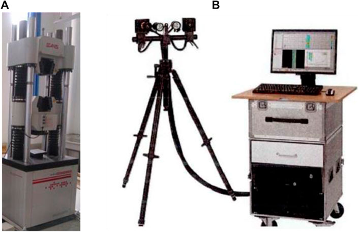
FIGURE 1. Monitoring system of rock uniaxial compression failure: (A) Universal testing machine; (B) ARAMIS strain measurement system.
2.2 Analysis of experimental results
The rock samples used in this experiment are taken from the low permeability tight sandstone reservoir of Chang 6, Zhenying area, Ordos Basin. The rock samples in this area are mainly lithic feldspar sandstone and feldspar lithic sandstone. A total of 9 standard cores with a height of 50 mm and a diameter of 25 mm are taken from the low permeability tight sandstone reservoir at a depth of 900–1,600 m, and the loading rate is 0.01 mm/s during the experiment. Three representative cores with numbers A3, A6 and A7 are selected for results analysis in those experimental results.
Figure 2 and Figure 3 show the stress-strain curve and failure process of core A3. Corresponding feature points such as A, B, C and D can be found in the curve in Figure 2. The curve can be divided into four stages, namely, OA stage, AB stage, BC stage and CD stage. The OA stage is the pore and fracture compaction stage. The micro-fractures and structural planes in the core will gradually close under the action of external pressure. The deformation in this stage is nonlinear, showing an upward concave trend, and the stiffness of the sample will gradually increase. Phase AB is a linear elastic process, and the stress-strain curve is approximately straight line. It can be find that the stiffness of the specimen is basically kept constant. The BC stage is the unstable development stage of the fracture. With the increase of the external load of the rock, the stress concentration at the fractures and pores inside the rock becomes more and more obvious. The fracture changes from stable expansion to unstable expansion, and the energy inside the rock gathers rapidly. When it extends to the critical energy release point, the fracture develops rapidly into a macroscopic fracture. When it develops to a certain stage, the stress will reach the peak strength of 52.01 MPa, that is, point C. In the BC stage, shear fractures are formed at the end of the core and extended rapidly. With the increase of stress, new shear fractures are formed and quickly connected with the previous shear fractures. At this time, the surface of the sample remained intact and do not collapse, as shown in Figure 3. The CD stage is the post-rupture stage. Under the action of macroscopic cracks, the internal structure of the core is destroyed and continues to load. The macroscopic cracks penetrate through each other and form the macroscopic fracture surface.
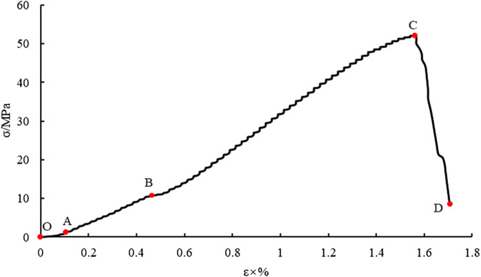
FIGURE 2. Stress-strain curve of core A3.
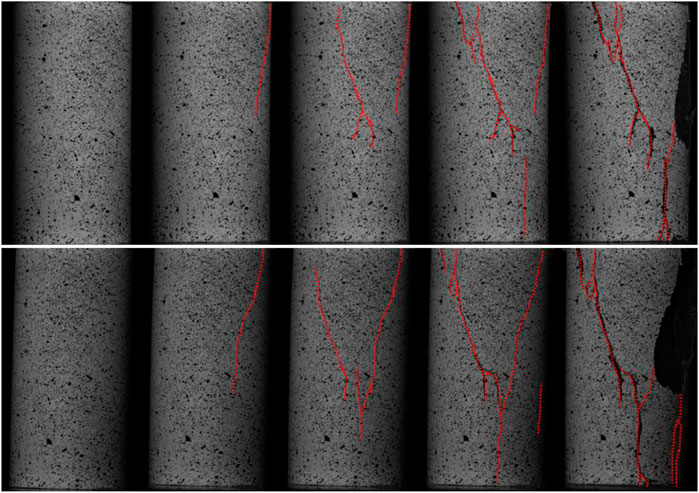
FIGURE 3. Failure process of core sample A3, the upper part is shot by the left camera, the lower part is shot by the right camera, and the red dotted line indicates the fracture.
Figure 4 and Figure 5 show the stress-strain curve and core failure process of A6 core. The stress-strain curve follows the O-A-B-C process, which is similar to the process of A3 core, including pore and fracture compaction stage, linear elastic stage and fracture unstable development stage. After the peak stress point C, the rock still has some residual strength, which is due to the core failure in the BC stage is split failure, in other words, a tensile fracture is produced. After the peak stress, there are new shear fractures and tensile fractures generated, when the internal fractures of the core have not yet penetrated the whole core. Following the redistribution of stresses within the core, the sample showed a certain increase in stress at point D and finally fell to point E. At this time, a number of tensile fractures and shear fractures occurred in the sample, and the internal structure of the sample is damaged, as shown in Figure 5.
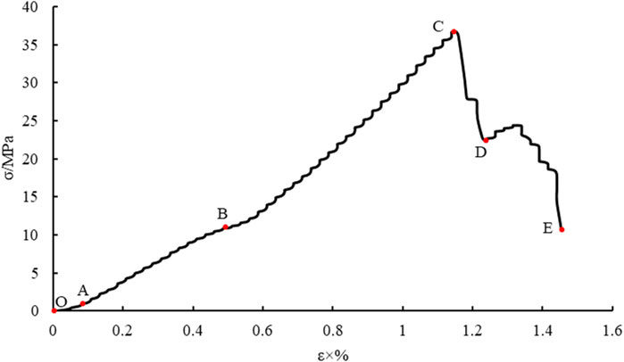
FIGURE 4. Stress-strain curve of core A6.
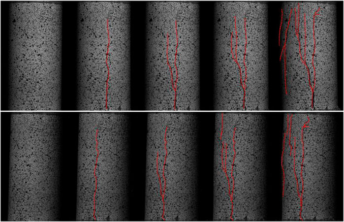
FIGURE 5. Failure process of core sample A6 the upper part is shot by the left camera, the lower part is shot by the right camera, and the red dotted line indicates the fracture.
Figure 6 shows the stress-strain curve of core A7, which has a double peak stress intensity, and the uniaxial compression process stage before point C is similar to that of core A3 and A6.
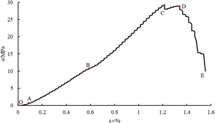
FIGURE 6. Stress-strain curve of core A7.
The first peak strength (29.07 MPa) at point C is due to shear fractures appearing at the top of the core with the increase of stress and strain in section BC, resulting in local fractures in the core. Local instability leads to the reduction of the core bearing capacity, but the overall structure of the core is not damaged, as shown in Figure 7. When the stress drops to a certain extent, the internal stress of the core is redistributed, and the ability of the core to withstand external loads increases. At the same time, the core cracked under the combined action of tension and shear, which expanded rapidly and the stress reached the second peak strength (28.94 MPa) at point D. Continuing to apply the load, the fracture penetrates the entire specimen, and the interior of the core is damaged, so that the stress falls rapidly to the E point, while the opening of the fracture increases.
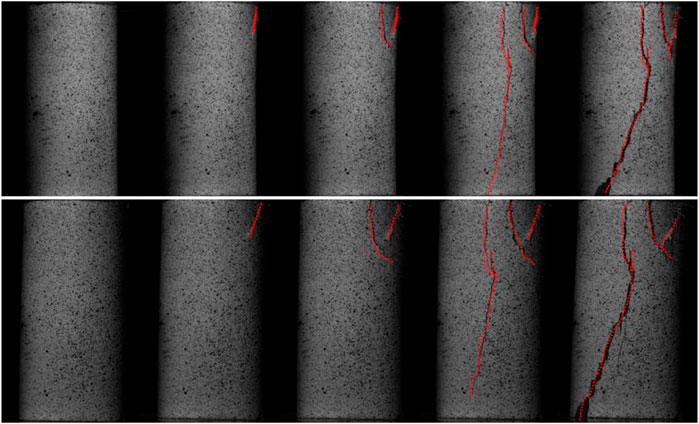
FIGURE 7. Failure process of core sample A7, the upper part is shot by the left camera, the lower part is shot by the right camera, and the red dotted line indicates the fracture.
3 Basic theory of particle discrete element method
Most of the large deformation in engineering is interpreted as the relative movement along various soft surfaces and contact zones. The deformation of these materials mainly comes from the slip and rotation of particles and the opening and locking of the contact interface, rather than from the deformation of a single particle itself. In order to obtain the internal mechanical properties of the rock, the rock can be regarded as a particle binder with complex shape, as shown in Figure 8A. Cundall proposed the discrete element method in 1979, which is gradually developed into the block discrete element method and the particle discrete element method (Cundall and Strack, 1979). Particle discrete element method is used to simulate the motion and interaction of granular medium by circular (or polygon) discrete element method, which does not need to add other conditions to simulate the rock fracture process indirectly. The parallel bond model and parallel joint model proposed by Potyondy can directly simulate the rock fracture process with nonlinear (Potyondy and Cundall, 2004), heterogeneous and anisotropic characteristics, and this method can study the mechanical properties of rock at mesoscale. Therefore, the particle discrete element method is selected for simulation in this paper. The particle discrete element method makes the following assumptions in the simulation process.
(1) The particle unit is a rigid body.
(2) Contact occurs in a very small range, that is, point contact.
(3) The contact is flexible contact, and the contact is allowed to have a certain amount of “overlap".
(4) The amount of “overlap” is related to the contact force, and the amount of “overlap” is small compared with the particle size.
(5) The contact has a special connection strength.
(6) The particle unit is circular (or spherical).
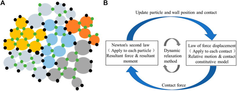
FIGURE 8. Particle discrete element method: (A) Rock mass model; (B) Calculating the cycle process (Potyondy, 2012).
The particle discrete element method uses the dynamic relaxation method to calculate and transforms the nonlinear statics problem into the dynamic problem to solve, which can reduce the computational storage and thus reduce the waste of computing resources. The cyclic process of particle discrete element method in calculation is shown in Figure 8B. The contact force and displacement between particles are updated according to the physical equation (force-displacement equation) and the equation of motion (Newton’s second law). In calculation, the generation of fractures in the specimen is automatically judged by the constitutive model used and realized automatically within the program.
(1) Physical equations - force and displacement equations
The force-displacement equation describes the direct relationship between the contact force and the relative displacement at the contact point between particles. Assuming that the normal contact force at the contact is Fn N) and the relative displacement is un m), the tangential force at the contact is described by increment, that is, the tangential force increment at the contact is ∆Fs N) and the relative displacement is us m). The normal force and tangential forces-displacement equation at the contact is expressed by the following formula:
Where
(2) Equations of motion - Newton’s second Law
In the discrete element method, the particle is assumed to be a rigid body, and the contact force exists between the particle and the particle. Under the action of external forces, the particles are in an unbalanced state, which will cause the particles to generate acceleration and velocity. At this time, the particles will produce rotation and dynamic behavior, and the contact force will be updated with the change of particle force and displacement. Assuming that at time t s), the resultant force of particles in the direction i is Fi, the bending moment is Mi (Nm), the mass of particles is m (kg), and the moment of inertia is Ii (kgm2), then the translational acceleration üi (m/s2) and rotational acceleration
At t+∆t/2, the translational velocity and rotational velocity of the particle in the direction i are as follows:
where
At t+∆t, the displacement of the particle in the i direction is as follows:
(3) Boundary conditions
In the discrete element method, the particle system can be loaded by assigning force or velocity to the particle, and the fixed edge particles can be used as the boundary constraint of the particle system. The boundary setting is flexible, and complex boundary conditions can be realized by writing functions.
(4) Constitutive model selection
In the particle discrete element method, the constitutive model of the material is defined by assigning the contact model to the contact between particles. It mainly includes four models: linear parallel bond model (Wu et al., 2021), flat-joint model (Potyondy, 2012), smooth-joint model (Fener et al., 2005)and soft-bond model (Huang et al., 2023). The flat-joint model is composed of rigid grains, and the grains are bonded by the contact of the flat-joint. The grains are composed of circular (2D) or spherical (3D) particles and notional surfaces. A grain surface can have multiple abstract surface units, and the abstract surface unit is rigidly connected with the corresponding grain. Therefore, the effective contact between the grains becomes the contact between the abstract surfaces. Flat-joint contact describes the behavior of the intermediate contact surface between abstract surfaces, as shown in Figure 9. In the two-dimensional model, the contact is a straight-line segment that can be discretized into several small units of equal length. In the three-dimensional model, the contact is a disc with a certain thickness, which can be discretized into a number of small units of equal volume from the radial and circular directions. Each element may be bonded, non-bonded with friction, so that the mechanism behavior of the intermediate contact surface may be bonded, non-bonded friction type, or vary along the contact surface. Compared with the linear parallel bonding model, this model can solve the problems such as low compression-tensile strength ratio, small internal friction angle and linear strength envelope. Compared with the linear parallel bond model, this model can solve problems such as low compression-tensile strength ratio, small internal friction angle, linear strength envelope and so on. The element failure at the bond adopts the constitutive relation curve of Figure 10. Since the contact in the flat-joint model contains multiple elements, the failure of each element remains independent, so the model can characterize the damage process in the failure of the specimen.
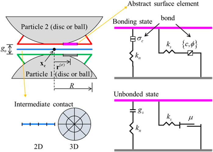
FIGURE 9. Schematic diagram of flat-joint model (Potyondy, 2012).
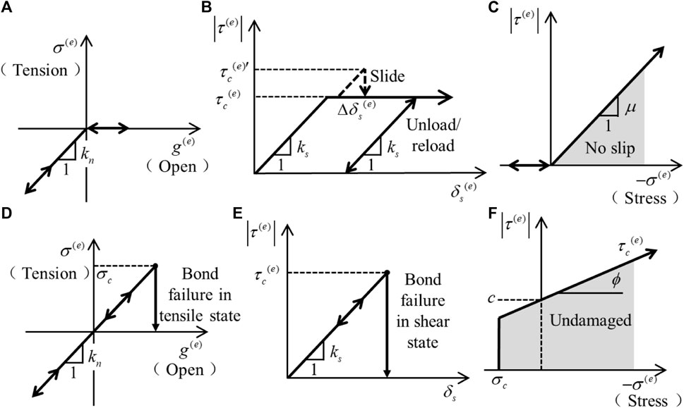
FIGURE 10. Constitutive relation curve of the flat-joint model, a-c Is the force-displacement curve of the unbonded flat-joint element, d-f Is the force-displacement curve of the flat-joint element in the bonded state: (A) Normal force and contact unit spacing curve; (B) Shear force and relative shear displacement curve; (C) Slip envelope; (D) Normal force and contact unit spacing curve; (E) Shear force and relative shear displacement curve; (F) Failure envelope.
4 Numerical simulation of microscopic damage
4.1 Numerical model
The flat-joint model can well simulate the microscopic damage of rock, so this paper adopts the model to investigate the microscopic parameters and damage process of rock. Some scholars have carried out sensitivity analysis on the microscopic parameters such as modulus (Ec) stiffness ratio (Kn/Ks), tensile strength (σt), bond strength (C)l, friction coefficient μ) and friction angle Φ) in the flat-joint model, and proposed a fast parameter calibration method (Wu and Xu, 2016). Therefore, this chapter does not reiterate the parameter calibration method. The physical parameters of tight sandstone, shale and coal rock in low permeability reservoirs are quite different. On the basis of previous studies, this paper selects the relevant macro parameters, and calibrates the meso parameters for rock uniaxial compression experiment and numerical calculation. The macro and meso parameters of rock are shown in Table 1. The sample used for numerical simulation is 100 mm in height and 50 mm in width. The contact between particles contains two abstract surface elements. The maximum particle radius is 0.6 mm, while the ratio of maximum radius to minimum radius is 1.8, and the particle density ρ) is 2,500 kg/m3.
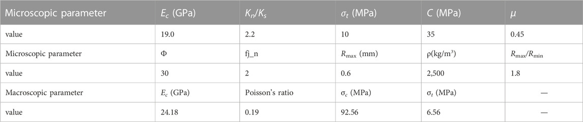
TABLE 1. Macro and microscopic parameters of rocks.
The particle contact in the plane joint model can be divided into several abstract surface units, each of which can break separately. Therefore, it is assumed that the contact is broken only when the last broken abstract surface unit at the contact between particles is broken, and microcracks appear at this time. The abstract surface units that are broken before the contact are the damage of the contact. This model is defined in this paper as the flat-joint damage model. In the ordinary flat-joint model, if the abstract surface element at the contact is broken, there will be a micro-fracture. Hence, the results of the flat-joint damage model are consistent with those of the flat-joint model, but the number of micro-fractures produced is inconsistent.
Figure 11 shows the numerical simulation results of the sample. Figure 11A shows that rock failure is accompanied by the generation of multiple fragments. At this time, multiple shear fractures and tensile fractures appear in the rock macroeconomically, moreover, the shear fractures run through the entire sample. Figure 11B shows the stress-strain curve of the specimen. There is a certain fluctuation in the initial stress increase of the curve, which is due to the stress change caused by the decrease of the porosity of the sample under compression and the densification of the particle structure. While the stress continues to increase, the stress-strain curves show linear characteristics, and there are micro-fractures in the specimen. It can be seen from Figure 12 that the generated micro-fractures are mainly tensile failure micro-fractures. The number of tensile micro-fractures in the flat-joint damage model is significantly lower than that in the flat-joint model, that is, there are two failure modes between rock particles. With the increase of stress, the shear failure micro-fractures gradually appear in the sample. The comparison of tensile micro-fractures in two different models shows that the number of micro-fractures in contact damage and tensile failure continues to increase. When the stress reaches its peak, the shear failure micro-fractures increase rapidly, and the tensile failure micro-fractures increase linearly. When the strain exceeds the peak strength, the stress decreases, and the number of shear failure micro-fractures and tensile micro-fractures continues to increase. At this time, the rock sample is destroyed and a V-shaped shear fracture is formed. After stopping loading, a total of 6,265 micro-fractures are generated in the flat-joint damage model (including 4,968 tensile failure micro-fractures and 1,297 shear failure micro-fractures), and a total of 13,771 micro-fractures are generated in the flat-joint model (including 11,658 tensile failure micro-fractures and 2,113 shear failure micro-fractures). The number of tensile break micro-fractures in the flat-joint model is more than twice that of those in the flat-joint damage model. Therefore, in the process of core failure, there are two failure modes of shear failure and tensile failure at the contact, but the damage is mainly tensile failure. After reaching the peak stress, the shear micro-fractures appear rapidly and gradually form a V-shaped shear fracture throughout the whole specimen.
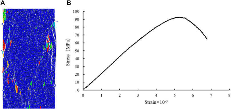
FIGURE 11. Numerical simulation of uniaxial compression, when the strength is 70% of the peak strength, the loading is stopped: (A) Failure pattern of specimens (multiple particles of the same color are rock fragments); (B) Stress-strain curve.
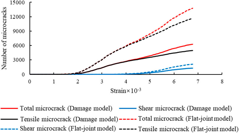
FIGURE 12. The variation curve of micro-fractures with strain during uniaxial compression failure of rock.
4.2 Influence of microscopic parameters on compression-tensile strength ratio and micro-fracture
Compressive strength, tensile strength and the compression and tension ratio are important factors affecting the mechanical properties of rock (Fener et al., 2005; Nazir et al., 2013). At the same time, the type of micro-fractures is an important factor affecting rock failure. Therefore, based on the above-mentioned uniaxial compression damage simulation research of rock, the numerical simulation of uniaxial compression and direct tension is further carried out to explore the influence of microscopic parameters on compressive strength, tensile strength, compression-tensile strength ratio and the change of fracture type.
(1) The effect of the microscopic modulus (Ec)
Figure 13 shows the influence curve of compressive strength and tensile strength with the change of microscopic parameter modulus. With the increase of microscopic modulus, the tensile strength changes little, the compressive strength increases rapidly at first and then slowly, while the compression-tensile strength ratio remains above 10, which is consistent with the trend of compressive strength. Therefore, the microscopic modulus has a small effect on the tensile strength and a great effect on the compressive strength, as well as a significant effect on the compression-tensile strength ratio.
(2) Influence of microscopic stiffness ratio (Kn/Ks)
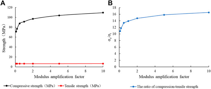
FIGURE 13. Relation curve between modulus (Ec) and strength: (A) Modulus (Ec); (B) Compression-tensile strength ratio.
Figure 14 shows the influence curve of the meso-parameter stiffness ratio on the strength. When the stiffness ratio is within the range of 1–2.4, the compressive strength fluctuates up and down to a certain extent. After the stiffness ratio is greater than 2.4, the tensile strength decreases with the increase of the stiffness ratio. The tensile strength decreases with the increase of microscopic stiffness ratio, while the compression-tensile strength ratio increases overall. Therefore, the variation of microscopic stiffness ratio has a definite effect on the compressive strength, tensile strength and compression-tensile strength ratio.
(3) The influence of microscopic friction coefficient μ) and microscopic friction angle Φ)
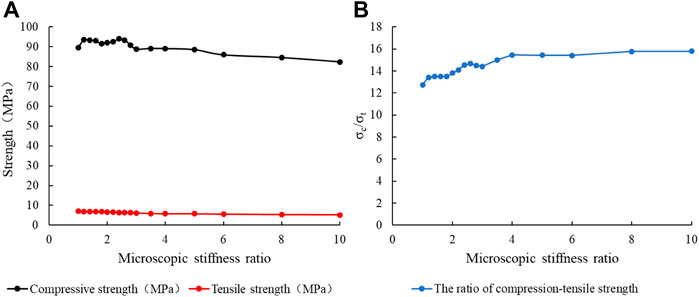
FIGURE 14. Relation curve between microscopic stiffness ratio and strength: (A) Microscopic stiffness ratio (Kn/Ks); (B) Compression-tensile strength ratio.
The friction coefficient μ) and the friction angle Φ) of the microscopic parameters have slight effect on the tensile strength, while the compressive strength and the compression-tensile strength ratio have some influence. As the microscopic coefficient of friction increases, the compressive strength and compression ratio increase, as shown in Figure 15 and Figure 16. The influence of microscopic friction angle on compressive strength and compression-tensile strength ratio is more significant than that of microscopic friction coefficient.
(4) Influence of microscopic tensile strength (σt)
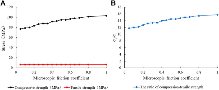
FIGURE 15. Relation curve between microscopic friction coefficient (μ) and microscopic strength: (A) Microscopic friction coefficient (μ); (B) Microscopic compression-tensile strength ratio.
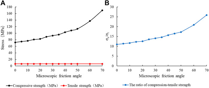
FIGURE 16. Relation curve between friction angle (Φ) and strength: (A) Friction angle (Φ); (B) Compression-tensile strength ratio.
Figure 17 shows the relationship between microscopic tensile strength and strength. When the microscopic tensile strength is in the range of 1–50 MPa, the compressive strength and tensile strength increase with the increase of microscopic tensile strength. However, the compression-tensile strength ratio is opposite. This is because as the inter-particle microscopic tensile strength increases, the resistance to tensile stress inside the specimen increases, and the proportion of tensile micro-fractures in all micro-fractures decreases, while the shear micro-fractures increase, as shown in Figure 18. When the inter-particle tensile strength increases to greater than the maximum shear stress inside the sample, there will be all shear micro-fractures inside the sample during the uniaxial compression test. That is to say, when the microscopic tensile strength increases from 50 MPa to 80 MPa, the compressive strength and tensile strength change little, at the same time, the ratio of compression-tensile strength also changes little. When the microscopic tensile strength exceeds 80 MPa, the compressive strength, tensile strength and compression-tensile strength ratio will remain unchanged.
(5) Effect of microscopic cohesion C)
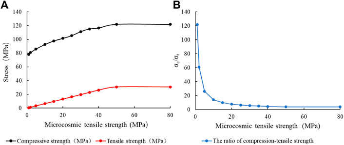
FIGURE 17. Relationship between microscopic tensile strength and strength: (A) Microscopic tensile strength (σt); (B) Compression-tensile strength ratio.

FIGURE 18. Influence curve of microscopic tensile strength (σc) on micro-fracture (UCS).
Figure 19 shows the relationship between microscopic cohesion and strength. When the microscopic cohesion is within 5 MPa, the internal tensile strength of the sample is larger than the shear strength, so the micro-fractures of the sample are all shear micro-fractures (Figure 20). The tensile strength and compressive strength increase with the increase of microscopic cohesion, while the compression-tensile strength ratio decreases. When the microscopic cohesion is greater than 10 MPa, the compressive strength increases with the increase of the microscopic cohesion, the tensile strength remains unchanged, the compression-tensile strength ratio is consistent with the trend of the compressive strength, and the shear micro-fracture will decrease while the tensile micro-facture will increase.
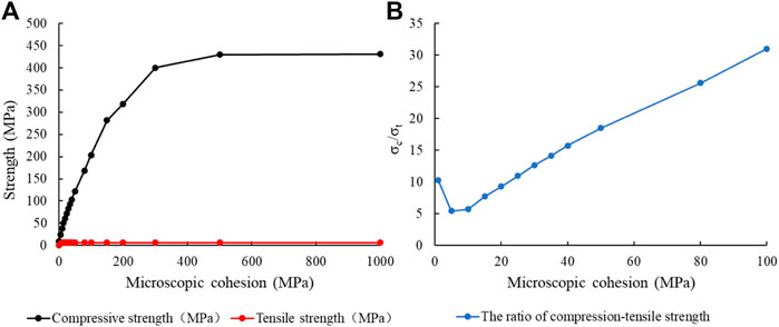
FIGURE 19. Relation curve between cohesion (C) and strength: (A) Microscopic cohesion (C); (B) Compression-tensile strength ratio.
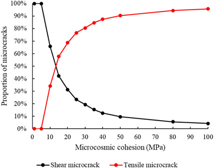
FIGURE 20. Influence curve of Microscopic cohesion (C) on micro-fracture (UCS).
5 Discussion
The microscopic parameters of rock are one of the important factors affecting the mechanical properties of rock. It is a key step to reveal the damage mechanism of rock by clarifying the change mechanism of rock properties under various parameters. The above research shows that, in addition to the tensile strength (microscopic), the rest of the rock meso-parameters change the ratio between the two micro-fractures by affecting the compressive strength of the rock. Under conventional conditions, the rock sample is squeezed from the height direction by uniaxial compression, and the two sides of the rock sample are continuously expanding outward under the action of internal force. Since the compressive strength of the rock is much greater than the tensile strength, the ability of the rock sample to withstand external expansion is much lower than the ability to withstand pressure. At this time, the inside of the rock sample slips downward while expanding to both sides, forming a large number of tensile micro-fractures, and the surface of the rock sample shows obvious V-shaped fractures. The compressive strength of the rock increases with the increase of rock microscopic parameters, but the tensile strength is almost unchanged. Compared with the normal condition, the vertical bearing capacity of the rock is greatly enhanced. Under the same pressure, the vertical displacement of the rock sample is smaller, but the outward expansion trend on both sides is almost unchanged, so it is difficult for the fracture to appear as a V-shape. However, the increase of pressure bearing capacity will inevitably lead to the accumulation of a large amount of pressure inside the rock, making the rock fracture more sudden and lack of buffer stage.
The absence of fracture buffer stage will make the rock fracture change from ductile failure to brittle failure, which is obviously unfavorable. In order to effectively identify the mechanism of rock failure, the ratio of compressive strength to tensile strength can be introduced to effectively predict the ratio of shear micro-fractures and tensile micro-fractures during rock failure, so as to determine the fracture mode of rock. However, how to accurately locate the transition point of rock fracture mechanism under compression-tensile strength ratio is still a difficult problem to be solved.
6 Conclusion
In order to study the fracture evolution process of low permeability sandstone, a laboratory uniaxial compression experiment is conducted to investigate the failure mode and evolution process of rock. Secondly, using the discrete element method, the damage process of rock under uniaxial compression is simulated by the flat-joint model which can characterize the damage. The influence of various microscopic parameters on the strength of the sample and the type of micro-fractures are analyzed. The results show that.
(1) The fracture evolution is complex and varied, and the failure modes include tensile failure, shear failure, and tensile-shear failure;
(2) Internal micro-fractures will interconnect during rock destruction to form primary fractures through the rock mass, while secondary micro-fractures will also be generated;
(3) With the increase of external pressure, the rock mainly produces tensile micro-fractures accompanied by a few shear micro-fractures. When the rock damage reaches a certain extent, the shear micro-fractures and tensile micro-fractures increase rapidly. At this point, the micro-fractures interconnect with each other to form macroscopic main fractures and secondary fractures, and the rock presents V-shaped shear failure.
(4) Rock microscopic parameters mainly change the ratio between the two kinds of micro-fractures by affecting the compressive strength of the rock. The larger the microscopic parameters, the greater the compressive strength of the rock and the more tensile micro-fractures.
Data availability statement
The raw data supporting the conclusion of this article will be made available by the authors, without undue reservation.
Author contributions
JH: Data curation, Writing–original draft. JX: Software, Writing–original draft. XL: Project administration, Writing–review and editing. YR: Data curation, Writing–original draft. KD: Data curation, Writing–original draft. JT: Data curation, Investigation, Writing–original draft.
Funding
The author(s) declare financial support was received for the research, authorship, and/or publication of this article.
Acknowledgments
The authors acknowledge the support provided by the Ph.D. Programs Foundation of Southwest University of Science and Technology (19zx7104), Open Research Fund of State Key Laboratory of Geomechanics and Geotechnical Engineering, Institute of Rock and Soil Mechanics, Chinese Academy of Sciences (Grant No. Z020009), and natural science starting project of SWPU (No.2022QHZ009).
Conflict of interest
JX was employed by Downhole Operation Company, CNPC Xibu Drilling Engineering Co, Ltd.
The remaining authors declare that the research was conducted in the absence of any commercial or financial relationships that could be construed as a potential conflict of interest.
Publisher’s note
All claims expressed in this article are solely those of the authors and do not necessarily represent those of their affiliated organizations, or those of the publisher, the editors and the reviewers. Any product that may be evaluated in this article, or claim that may be made by its manufacturer, is not guaranteed or endorsed by the publisher.
References
Bai, L., Huang, W., Qin, J., Zhang, Z., Ba, Z., Bai, Z., et al. (2023). Genesis and microscopic characteristics of tight reservoirs in the Fengcheng Formation, at the southern margin of the Mahu Sag. Energy Geosci. 4, 100162. doi:10.1016/j.engeos.2023.100162
Cundall, P. A., and Strack, O. D. (1979). A discrete numerical model for granular assemblies. Geotechnique 29, 47–65. doi:10.1680/geot.1979.29.1.47
Detournay, C., Damjanac, B., Torres, M., Cundall, P., Ligocki, L., and Gil, I. (2022). Heat advection and forced convection in a lattice code – implementation and geothermal applications. Rock Mech. Bull. 1, 100004. doi:10.1016/j.rockmb.2022.100004
Dontsov, E. V. (2022). Analysis of a constant height hydraulic fracture driven by a power-law fluid. Rock Mech. Bull. 1, 100003. doi:10.1016/j.rockmb.2022.100003
Du, K., Li, X., Su, R., Tao, M., Lv, S., Luo, J., et al. (2022). Shape ratio effects on the mechanical characteristics of rectangular prism rocks and isolated pillars under uniaxial compression. Int. J. Min. Sci. Technol. 32, 347–362. doi:10.1016/j.ijmst.2022.01.004
Fener, M., Kahraman, S., Bilgil, A., and Gunaydin, O. (2005). A comparative evaluation of indirect methods to estimate the compressive strength of rocks. Rock Mech. Rock Eng. 38, 329–343. doi:10.1007/s00603-005-0061-8
He, R., Yang, J., Li, L., Yang, Z., Chen, W., Zeng, J., et al. (2023). Investigating the simultaneous fracture propagation from multiple perforation clusters in horizontal wells using 3D block discrete element method. Front. Earth Sci. 11, 1–19. doi:10.3389/feart.2023.1115054
Huang, L., Dontsov, E., Fu, H., Lei, Y., Weng, D., and Zhang, F. (2022a). Hydraulic fracture height growth in layered rocks: perspective from DEM simulation of different propagation regimes. Int. J. Solids Struct. 238, 111395. doi:10.1016/j.ijsolstr.2021.111395
Huang, L., Tan, J., Fu, H., Liu, J., Chen, X., Liao, X., et al. (2023). The non-plane initiation and propagation mechanism of multiple hydraulic fractures in tight reservoirs considering stress shadow effects. Eng. Fract. Mech. 292, 109570. doi:10.1016/j.engfracmech.2023.109570
Huang, L., Liu, J., Ji, Y., Gong, X., and Qin, L. (2018). A review of multiscale expansion of low permeability reservoir cracks. Petroleum 4, 115–125. doi:10.1016/j.petlm.2017.09.002
Huang, L., Liu, J., Zhang, F., Dontsov, E., and Damjanac, B. (2019). Exploring the influence of rock inherent heterogeneity and grain size on hydraulic fracturing using discrete element modeling. Int. J. Solids Struct. 176–177, 207–220. doi:10.1016/j.ijsolstr.2019.06.018
Huang, L., Liu, J., Zhang, F., Fu, H., Zhu, H., and Damjanac, B. (2020). 3D lattice modeling of hydraulic fracture initiation and near-wellbore propagation for different perforation models. J. Pet. Sci. Eng. 191, 107169. doi:10.1016/j.petrol.2020.107169
Huang, Y., Yang, S., Tian, W., and Wu, S. (2022b). Experimental and DEM study on failure behavior and stress distribution of flawed sandstone specimens under uniaxial compression. Theor. Appl. Fract. Mech. 118, 103266. doi:10.1016/j.tafmec.2022.103266
Ji, Y., Wang, J., and Huang, L. (2015). Analysis on inflowing of the injecting Water in faulted formation. Adv. Mech. Eng. 7, 1–10. doi:10.1177/1687814015590294
Lai, Y., Zhao, K., He, Z., Yu, X., Yan, Y., Li, Q., et al. (2023). Fractal characteristics of rocks and mesoscopic fractures at different loading rates. Geomech. Energy Environ. 33, 100431. doi:10.1016/j.gete.2022.100431
Li, Q., Lu, H., Li, J., Wu, S., Wu, Y., Wen, L., et al. (2022). Characteristics and formation mechanism of the tight tuff reservoirs of the Upper Triassic Chang 7 member in the southern Ordos Basin, China. Mar. Pet. Geol. 139, 105625. doi:10.1016/j.marpetgeo.2022.105625
Liu, Y., Dong, X., Chen, Z., Hou, Y., Luo, Q., and Chen, Y. (2021). A novel experimental investigation on the occurrence state of fluids in microscale pores of tight reservoirs. J. Pet. Sci. Eng. 196, 107656. doi:10.1016/j.petrol.2020.107656
Luo, H., Xie, J., Huang, L., Wu, J., Shi, X., Bai, Y., et al. (2022). Multiscale sensitivity analysis of hydraulic fracturing parameters based on dimensionless analysis method. Lithosphere 2022. doi:10.2113/2022/9708300
Nazir, R., Momeni, E., Armaghani, D. J., and Amin, M. F. M. (2013). Correlation between unconfined compressive strength and indirect tensile strength of limestone rock samples. Electron. J. Geotech. Eng. 18 I, 1737–1746.
Potyondy, D. O. (2012). “A flat-jointed bonded-particle material for hard rock,” in 46th US rock mech./geomech. Symp (Chicago, Illinois: ACM), 1510–1519.
Potyondy, D. O., and Cundall, P. A. (2004). A bonded-particle model for rock. Int. J. Rock Mech. Min. Sci. 41, 1329–1364. doi:10.1016/j.ijrmms.2004.09.011
Tan, P., Jin, Y., Han, K., Hou, B., Guo, X., Gao, J., et al. (2017). Analysis of hydraulic fracture initiation and vertical propagation behavior in laminated shale formation. Fuel 206, 482–493. doi:10.1016/j.fuel.2017.05.033
Tan, P., Jin, Y., and Pang, H. (2021). Hydraulic fracture vertical propagation behavior in transversely isotropic layered shale formation with transition zone using XFEM-based CZM method. Eng. Fract. Mech. 248, 107707. doi:10.1016/j.engfracmech.2021.107707
Tan, P., Pang, H., Zhang, R., Jin, Y., Zhou, Y., Kao, J., et al. (2020). Experimental investigation into hydraulic fracture geometry and proppant migration characteristics for southeastern Sichuan deep shale reservoirs. J. Pet. Sci. Eng. 184, 106517. doi:10.1016/j.petrol.2019.106517
Tian, G., Deng, H., Xiao, Y., and Yu, S. (2022). Experimental study of multi-angle effects of micron-silica fume on micro-pore structure and macroscopic mechanical properties of rock-like material based on NMR and SEM. Mater. (Basel) 15, 3388. doi:10.3390/ma15093388
Wang, X., Song, Y., Guo, X., Chang, Q., Kong, Y., Zheng, M., et al. (2022). Pore-throat structure characteristics of tight reservoirs of the middle permian lucaogou formation in the jimsar sag, Junggar basin, northwest China. J. Pet. Sci. Eng. 208, 109245. doi:10.1016/j.petrol.2021.109245
Wu, M., Huang, R., and Wang, J. (2021). DEM simulations of cemented sands with a statistical representation of micro-bond parameters. Powder Technol. 379, 96–107. doi:10.1016/j.powtec.2020.10.047
Wu, S., and Xu, X. (2016). A study of three intrinsic problems of the classic discrete element method using flat-joint model. Rock Mech. Rock Eng. 49, 1813–1830. doi:10.1007/s00603-015-0890-z
Zhang, F., Damjanac, B., and Maxwell, S. (2019). Investigating hydraulic fracturing complexity in naturally fractured rock masses using fully coupled multiscale numerical modeling. Rock Mech. Rock Eng. 52, 5137–5160. doi:10.1007/s00603-019-01851-3
Zhang, F., Dontsov, E., and Mack, M. (2017). Fully coupled simulation of a hydraulic fracture interacting with natural fractures with a hybrid discrete-continuum method. Int. J. Numer. Anal. Methods Geomech. 41, 1430–1452. doi:10.1002/nag.2682
Zhang, F. S., Huang, L. K., Yang, L., Dontsov, E., Weng, D. W., Liang, H. B., et al. (2022). Numerical investigation on the effect of depletion-induced stress reorientation on infill well hydraulic fracture propagation. Pet. Sci. 19, 296–308. doi:10.1016/j.petsci.2021.09.014
Zhang, Z., Wang, E., Li, N., Zhang, H., Bai, Z., and Zhang, Y. (2023). Research on macroscopic mechanical properties and microscopic evolution characteristic of sandstone in thermal environment. Constr. Build. Mater. 366, 130152. doi:10.1016/j.conbuildmat.2022.130152
Keywords: tight reservoirs, uniaxial compression, damage mechanism, particle discrete elements, hydraulic fracturing
Citation: Huang J, Xing J, Liao X, Ren Y, Ding K and Tan J (2023) Study on mechanical properties and microscopic damage mechanism of tight sandstone reservoir under uniaxial compression. Front. Energy Res. 11:1272086. doi: 10.3389/fenrg.2023.1272086
Received: 03 August 2023; Accepted: 06 September 2023;
Published: 19 September 2023.
Edited by:
Peng Tan, CNPC Engineering Technology R & D Company Limited, ChinaCopyright © 2023 Huang, Xing, Liao, Ren, Ding and Tan. This is an open-access article distributed under the terms of the Creative Commons Attribution License (CC BY). The use, distribution or reproduction in other forums is permitted, provided the original author(s) and the copyright owner(s) are credited and that the original publication in this journal is cited, in accordance with accepted academic practice. No use, distribution or reproduction is permitted which does not comply with these terms.
*Correspondence: Xingchuan Liao, bGlhb3hjMTk5OEAxNjMuY29t