 Sobhy M. Abdelkader
 Ernest F. Morgan
 Tamer F. Megahed1,2
 Wesam Rohouma
 Omar Abdel-Rahim
- 1Electrical Power Engineering, Egypt-Japan University of Science and Technology (E-JUST), New Borg El-Arab City, Egypt
- 2Electrical Engineering Department, Faculty of Engineering, Mansoura University, El-Mansoura, Egypt
- 3Electrical Power and Renewable Energy, University of Doha for Science and Technology, Doha, Qatar
- 4Electrical Engineering Department, Faculty of Engineering, Aswan University, Aswan, Egypt
Wind energy has emerged as a prominent player in the realm of renewable energy sources, both in terms of capacity and technological adaptability. Among the various renewable energy technologies, wind turbine generators stand out as the most widely employed. Recently, gearless permanent magnet synchronous generators have gained traction in the wind energy sector due to their appealing features, such as reduced maintenance costs and the elimination of gearboxes. Nevertheless, challenges remain, particularly concerning the grid-friendly integration of wind turbines, specifically with regard to high voltage ride-through (HVRT) and low voltage ride-through (LVRT) improvements. These challenges pose a threat to grid stability, impede Wind Turbine Generator performance, and may lead to significant damage to wind turbines. To address these concerns, this research proposes an integrated strategy that combines a model predictive control (MPC) superconducting magnetic energy storage (SMES) device with a modified WTG grid-side converter control. By coupling SMES devices to the dc-link of Permanent Magnet Synchronous Generator WTGs, the proposed approach aims to achieve an overvoltage suppression effect during grid disturbances and provide support for grid reactive power. Through various test scenarios, the feasibility and practicality of this suggested technique are demonstrated.
1 Introduction
Governments worldwide have shown significant interest in renewable energy production, leading to substantial investments and development efforts. The wind sector experienced remarkable growth. Globally, 77.6 GW of new wind power capacity was connected to power grids in 2022, bringing total installed wind capacity to 906 GW, a year-on-year (YoY) growth of 9%. Projections indicate that the total installed wind capacity will reach 2 TW by 2030 (Global Wind Energy Council, 2023). This surge in wind energy has prompted network operators and researchers to focus on enhancing the efficiency of wind power generators integrated into electrical grids. Consequently, the integration of wind power facilities using permanent magnet synchronous generators (PMSGs) into utility networks is on the rise (Jiang et al., 2021; Abdel-Rahim et al., 2022; Morgan et al., 2022a; Raouf et al., 2023).
PMSG wind turbine generators (WTGs) offer numerous advantages, such as excellent operational efficiency, self-excitation capability, gearbox elimination, high power factor, and reliability (Abdel-Rahim et al., 2014). However, the impact of wind energy on power networks necessitates addressing issues related to security, stability, and operation. Controlling voltage, frequency, and power while avoiding network disruptions is crucial. In the event of a malfunction, it was previously acceptable to isolate wind energy conversion systems (WECs) from the electric grid. However, to prevent power outages, strict grid codes have been established by transmission line operators worldwide, mandating wind turbines to remain connected to the grid even under adverse conditions. Failure to provide adequate protection can lead to disconnection of WTGs or damage to turbine and converter switches (Lyu et al., 2020).
To address these challenges, fault ride-through (FRT) methods have been developed. Notably, direct-drive PMSG wind turbines (WTs) have the advantage of contributing minimally to fault currents, allowing them to meet FRT criteria to some extent. However, they lack the ability to stabilize system voltage during grid variations. To maintain grid voltage, WTGs must contribute reactive power (López et al., 2009; Sarkar et al., 2018). As a result, FRT is crucial for WTs to withstand voltage fluctuations without disconnection from the grid. The main focus of FRT in direct-drive PMSG WTGs is to manage excess energy stored in the WTG’s internal dc-link while supporting the grid with reactive power during disturbances (Hu et al., 2017).
Various FRT methods incorporate hardware schemes, such as braking choppers, dynamic voltage restorers (DVRs), energy storage systems (ESS), and STATCOM, as well as soft schemes like modified control for back-to-back converters (Benali et al., 2018; Djagarov et al., 2019; Huang et al., 2020a; Kim and Kim, 2021; Nasiri and Arzani, 2022). To enhance grid connection efficiency, using ESS to offset erratic active power supply during grid faults has been considered favorable (Makhad et al., 2022). High-capacity energy storage devices play a crucial role in quick dynamic power adjustment, which improves transient stability and guarantees consistent electricity output (Abhinav and Pindoriya, 2016). However, batteries used for reactive power assistance result in frequent charging and discharging cycles, reducing battery lifespan (Das et al., 2018). Hence, superconducting magnetic energy storage (SMES) is a more suitable option for FRT compared to other high-capacity energy storage devices like battery energy storage (BES). SMES devices offer advantages such as high energy storage efficiency, minimal self-discharge rate (when coupled with a superconducting switch), extended lifespan, and minimal environmental impact (Bar et al., 2021). Research has shown that SMES outperforms BES in terms of faster response and better dc voltage stabilization in dc-dc converters (Nikolaidis and Poullikkas, 2018).
SMES devices are widely used in WTG applications, either integrated into the WTG’s dc-link or linked to the point of common coupling (PCC) outside the WTG. At the dc-link, SMES controls its dc-dc chopper to reduce excess power and compensate for reactive power from the WTG to the grid. When connected at PCC, SMES supports voltage and compensates for delivered wind power from PCC to the grid.
However, some SMES-based schemes that involve adding a dc-ac inverter and control adjustments in the external circuit can lead to increased capital costs and control complexity (Zheng et al., 2017; Morgan et al., 2022b). Additionally, these schemes may not be cost-effective since they require additional devices like SMES to enhance FRT in PMSG WTGs. A more viable approach is to incorporate a modified control scheme for the WTG to maintain the DC link voltage close to a constant. Various control methods have been employed to achieve this objective, including fuzzy logic controllers (FLCs) and artificial neural network (ANN) controllers. However, these methods have drawbacks, such as complex architecture and lengthy training times (Mukherjee and Rao, 2019; Ahsan and Mufti, 2020).
In contrast, proportional-integral (PI) controllers have proven effective in modern manufacturing processes due to their resilience, broad stability margin, simplicity, and low cost (Jannati et al., 2016). Despite these advantages, PI controllers may encounter challenges in heavy nonlinear systems, particularly when uncertainties are involved. Various optimization techniques, such as the genetic algorithm, continuous mixed p-norm (CMPN) algorithm, grey wolf optimizer, water cycle algorithm, and whale optimization algorithm, have been suggested for fine-tuning PI controllers for industrial applications (Dahiya et al., 2019; Qais et al., 2019; Qais et al., 2020a; Soliman et al., 2020; Joseph et al., 2022). While these algorithms excel in finding the best global optimum solution, they are time-consuming and require intricate flowcharts. To address these issues, the model predictive control (MPC) method is adopted in this study. MPC offers rapid dynamic response, adaptability to multiple variables and inequalities, improved resilience, and stability. MPC is extensively used in industry, has a straightforward calculating procedure, and has undergone rigorous long-term practice tests (Qais et al., 2020b; Chen et al., 2020).
Previous research has explored the coordination of SMES devices and modified converter control for other wind turbine types. However, these techniques cannot be directly applied to PMSG WTGs, necessitating further research into cooperative schemes involving enhanced WTG control and SMES to improve the stable grid connection of future wind farms.
To address these challenges, this paper presents a comprehensive control strategy that combines SMES with auxiliary reactive power support. A modified WTG converter control and a model predictive control SMES system are employed to achieve the objectives. The paper’s main contributions are as follows:
1) A cooperative control strategy is proposed to enhance FRT using SMES.
2) A prediction model of SMES is established, and a corresponding model predictive control method is proposed to track power instructions for storing, charging, and discharging. Simulation results compare the performance of MPC with other control algorithms.
2 FRT grid code requirement for PMSG wind turbines
Various countries have pursued diverse approaches to enhance their wind power generation capacities. In regions where the wind energy industry is well-established, grid codes have been implemented to accommodate the specific requirements of grid integration. One crucial aspect of wind power integration is the ability to withstand faults and disturbances in the grid, which is known as fault ride-through (FRT) capability (Abdel-Rahim and Funato, 2014; Huang et al., 2020b).
Utility grid standards impose requirements on wind turbine generators (WTGs) to possess sufficient High Voltage Ride-Through (HVRT) and Low Voltage Ride-Through (LVRT) capabilities. Figure 1 provides an illustrative example of the HVRT and LVRT criteria. According to these standards, the WTG should remain connected to the grid when the grid voltage falls within the shaded gray region. On the other hand, if the grid voltage exceeds this region, the WTG can safely trip without any adverse consequences. Moreover, when the terminal voltage ranges from 0.9 per unit (p.u.) to 1.1 p.u., the wind turbines should continue operating, but under different voltage conditions, a brief disconnection might be necessary (Luo et al., 2018; Abdel Aleem et al., 2017).
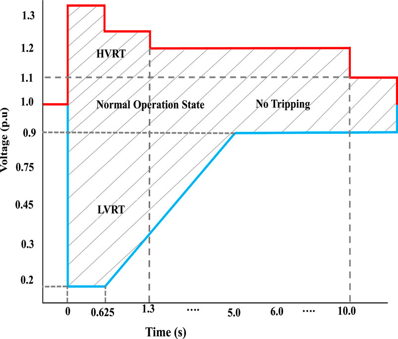
FIGURE 1. A typical grid code for fault ride-through (FRT).
3 Mathematical modeling of the proposed hybrid WECS-SMES
The comprehensive system under study is depicted in Figure 2, encompassing components such as a wind turbine (WT) model, a Permanent Magnet Synchronous Generator (PMSG), power converters, a Superconducting Magnetic Energy Storage (SMES) device, and a grid model. The proposed method entails the parallel connection of the SMES device to the direct current (dc) link of the 1.5 MW integrated WTG. The essential characteristics of the integrated 1.5 MW WTG are summarized in Table 1.
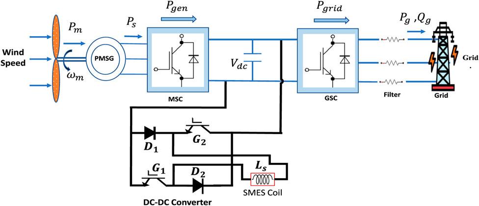
FIGURE 2. PMSG-SMES based wind turbine connected to the Grid.
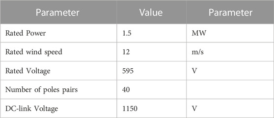
TABLE 1. Key features of the PMSG WTG system.
3.1 Mathematical modeling of WECS
The mechanical power produced from the wind by the PMSG-WT is expressed as (Okedu, 2022):
In Eq. 1,
Where
Eq. 2 incorporates coefficients
The variables in question are as follows:
3.2 Mathematical modeling of PMSG
The dynamic model of the PMSG wind turbine in the d-q reference rotating frame is presented as shown in reference (Wang et al., 2018).
In the dynamic model of the PMSG wind turbine, the following variables are involved:
The active and reactive power of the Permanent Magnet Synchronous Generator (PMSG) are expressed as follows:
The electro-torque of the wind generator with pole pairs (p) is represented as follows:
In the case of a surface-seated Permanent Magnet Synchronous Generator (PMSG), it is reasonable to assume that
3.3 SMES Modeling
Among the various commercial energy storage devices (ESD) available, superconducting magnetic energy storage (SMES) stands out due to its rapid response speed, high power density, and extended lifespan (Gouda et al., 2020). In this study, SMES is emulated as an inductor with negligible resistance. The DC-DC side of the converter comprises two Insulated Gate Bipolar Transistors (IGBT) and two diodes, enabling a bidirectional, two-quadrant operation of the SMES magnet. This allows the SMES to charge, store, and discharge energy while the current is positive. The switching pattern of the transistors is adjusted to produce either positive or negative voltage at the magnet’s terminals, turning it into an intrinsic zero-voltage device. The fundamental electrical circuit for the SMES chopper is depicted in Figure 3.
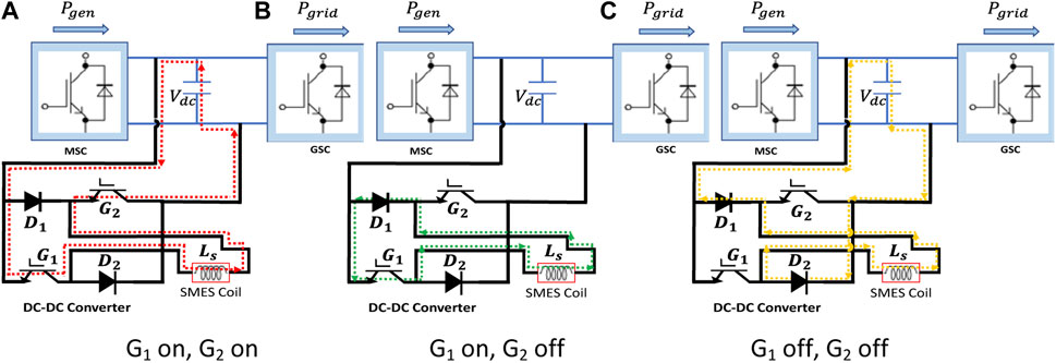
FIGURE 3. Operation mode of SMES (A) Charging mode (B) Standby mode (C) Discharging mode.
In the charging mode, when the controller commands the SMES to absorb energy, the current path is illustrated in Figure 3A. During this mode, IGBT G1 and IGBT G2 are activated to charge the SMES from the DC bus. The voltage V(t) across the inductor can be expressed as follows:
The expression for the energy stored in the SMES can be obtained as follows, taking into account the DC bus voltage (V), the coil inductance (
In the discharge mode, IGBT G1 and G2 are turned off, and the controller manages the duty cycle of IGBT G2 to achieve the desired output current
When the SMES does not require power exchange with the power grid, the chopper operates in standby mode to maintain the stored energy in the SMES. In this standby state, the current path is depicted in Figure 3C, where IGBT G1 remains continuously turned on, and IGBT G2 remains continuously turned off. The current flowing in the superconductor during the storage process can be represented as follows:
If the superconductor material exhibits zero resistance (
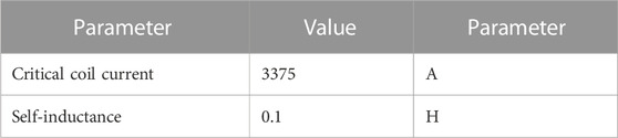
TABLE 2. Key features of SMES Tokyo Model (Xu et al., 2019).
4 Principle of operation
The dual operation modes of the protection circuit exist, as described below:
4.1 During voltage sag and swell
Eq. 21 illustrates the behavior of the DC link, where C and
During High Voltage Ride-Through (HVRT), if the grid voltage increases, the output of the MSC (
To address this issue, the excess energy received by the dc-link capacitor during voltage fluctuations needs to be dissipated, or alternatively, the total capacitance of the DC-link (C_Total) should be increased, as depicted in Eq. 22, to maintain the dc-link voltage within a safe range (De Siqueira and Peng, 2021).
4.2 Converter and SMES control
The primary aim of this study is to enhance the Fault Ride-Through (FRT) capability in the PMSG-based Wind Turbine Generator (WTG). To achieve this objective, the methods presented in Nielsen et al. (2010), which pertain to Machine and Grid Side Converter control, are adopted. Consequently, these methods will not be reiterated in this work. Instead, this section focuses on a modified control strategy for the grid-side converter that incorporates SMES to address the FRT issue, as illustrated in Figure 4.
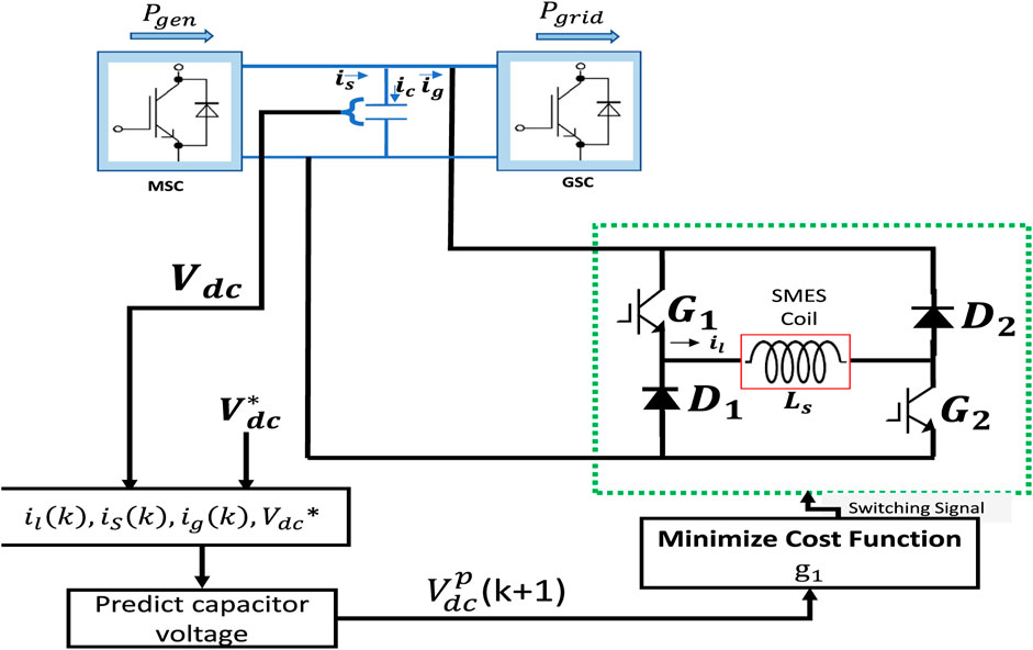
FIGURE 4. Schematic representation of the MPC-based SMES control system.
4.3 Model predictive control strategy for SMES
The dc-dc chopper operates with binary on and off settings. Consequently, it has a set of switching states that encompass all possible permutations. However, certain combinations leading to short-circuits in the DC link are avoided. To determine the optimal switching state of the dc-dc chopper corresponding to the dc-link voltage, an optimization process is carried out. Subsequently, the optimal switching states are applied. Unlike traditional PID control, where pulse width modulation (PWM) is used to generate switching signals for the converters, the MPC-based SMES system directly produces the required switching signals for the chopper. Figure 5 illustrates the predictive control method for the dc-dc chopper. For calculating the expected voltage across the dc link, the predicted current flowing through the SMES coil at the sampling time
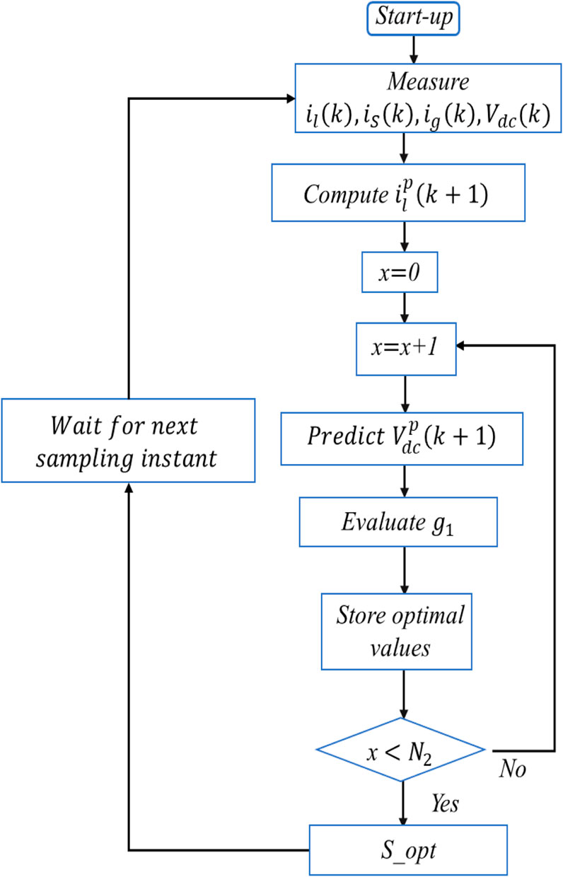
FIGURE 5. Algorithm for controlling the systems as implemented.
The expected SMES current at time k is given by:
Where,
With its accompanying switching function as:
Table 3 illustrates the complete switching sequence for the DC-DC chopper. Where
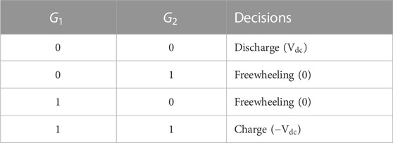
TABLE 3. DC-DC chopper Switching States.
At time k, the capacitor’s expected current is:
But since the SMES coil is considered already charged, the next available state is the discharge state, hence
The relationship between voltage and capacitor current is as follows:
The derivative capacitor voltage
where,
The cost functions
Where
Figure 6 depicts the control algorithm used by the MPC-based SMES system. The dc voltage forecast relies on Eq. 29.
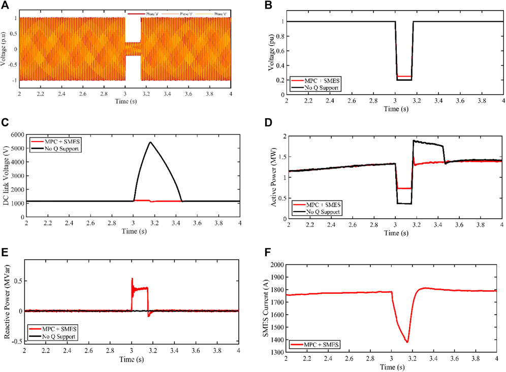
FIGURE 6. PMA wind generator response for 0.80pu balanced voltage sag (A) Phase abc of PCC voltage profile (B) RMS of Terminal voltage (C) DC-link voltage (D) Active power (E) Reactive power (F) SMES current profile.
4.4 Modified Grid Side Converter control
For grid voltage angle detection, a phase-locked loop (PLL) is utilized (Yuan et al., 2020). During regular operation, iqref is set to 0, enabling the Grid-Side Converter (GSC) to operate in unity power factor mode. However, when the WTG is in Fault Ride-Through (FRT) mode, the dynamic reactive current reference is determined based on the magnitude of the voltage dips, as expressed in Eq. 31.
In Eq. 32, K represents the coefficient, i_gqref denotes the reactive current reference, and V refers to the instantaneous terminal voltage.
The threshold current of the IGBT is denoted as
During High Voltage Ride-Through (HVRT) and Low Voltage Ride-Through (LVRT) events, the Grid-Side Converter (GSC) is configured to operate in the Q-priority mode. This means that the converter prioritizes the contribution of reactive current over the contribution of active current.
5 Case studies
In Matlab∖Simulink, a 1.5 MW PMSG-based WECS with a model predictive control SMES model is developed. The following are the conditions for the test case studies:
Case 1:. 80% balanced voltage sag.
Case 2:. 20% balanced voltage swell.
5.1 Case 1: Behaviours under 80% symmetrical voltage sag
In this experimental study, a balanced voltage drop of 0.80 pu is applied to the grid at t = 3s and persists for 150 m. Figure 6A illustrates the 0.80 pu voltage drop at the grid-connected point during the fault. The root mean square value of the voltage drop at the grid-connected point is depicted in Figure 6B. Without any Q support, the voltage at the grid-connected point peaks at 0.2 pu and gradually increases to 0.25 pu when the SMES is controlled by MPC (Model Predictive Control).
Figure 6C presents the behavior of the DC-link voltage. Without Q support, the DC-link voltage exhibits uncontrolled growth, exceeding the fault period, resulting in a 5,450 V increase over a time period of 3.5s, surpassing the fault duration. However, when MPC-controlled SMES is activated, the DC-link voltage is effectively regulated to 1,200 V, enabling the wind turbine to ride through the fault within the fault period.
Figure 6D depicts the active power management profile under two scenarios: without Q support and with SMES + MPC schemes. Without Q support, the grid’s active power decreases from its nominal value of 1.5 MW to approximately 0.365 MW until t = 3.47s, before returning to its nominal value. When SMES regulated by MPC is engaged, the grid-side active power is cushioned at around 0.736 MW until t = 3.15s, before returning to its nominal value.
Similarly, Figure 6E shows the behavior of the grid’s reactive power. Without any Q support mechanism, there is no grid reactive power support during the fault. However, with the MPC + SMES technique, the reactive power reaches 0.35 MVar to facilitate PCC (Point of Common Coupling) voltage recovery. As depicted in Figure 6F, the SMES’s active current is injected into the grid during this recovery period. Following the elimination of the grid fault, the SMES current, controlled by MPC, is increased to 1,750 A, ensuring that these operations remain below the SMES critical current threshold.
Table 4 provides a summary of the advantages of MPC in the proposed technique, as detailed in reference (Aimene et al., 2022). The comparison includes the percentage change in the DC-link voltage (Δ V_dc) and the control settling time (s). Table 4 demonstrates that the MPC + SMES technique, owing to its capability to handle control uncertainties, facilitates a reasonable system recovery.
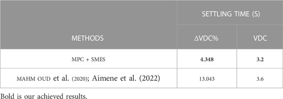
TABLE 4. Results for 0.80 pu balanced Voltage sag conditions.
5.2 Case 2: Behaviours under 20% symmetrical voltage swell
In this experimental study, a balanced voltage swell of 0.20 pu is applied to the grid at t = 3s and lasts for 150 m. Figure 7A illustrates the 0.20 pu voltage swell at the grid-connected point during the fault. The root mean square value of the voltage swell at the grid-connected point is depicted in Figure 7B.
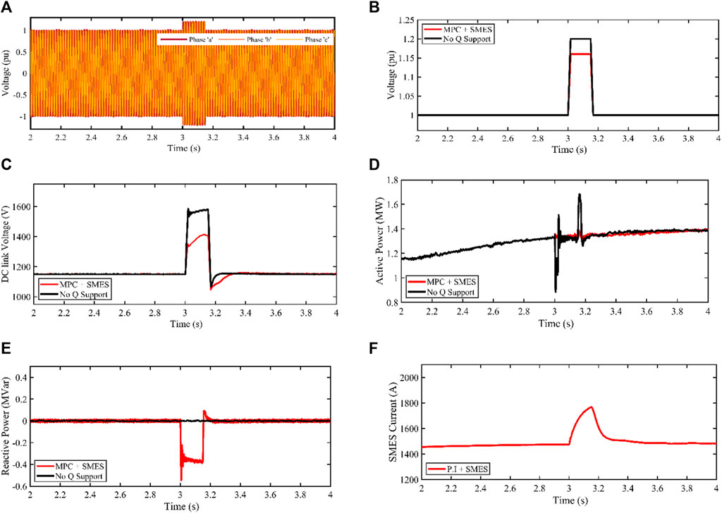
FIGURE 7. PMA wind generator response for 0.20 pu balanced voltage swell (A) Phase abc of PCC voltage profile (B) RMS Terminal voltage (C) DC-link voltage (D) Active power (E) Reactive power (F) SMES current profile.
Without any Q support, the voltage at the grid-connected point peaks at 1.2 pu and gradually decreases to 1.16 pu when the SMES is controlled by MPC (Model Predictive Control). The DC-link behavior is shown in Figure 7C. If no Q support mechanism is introduced, the DC-link voltage would increase uncontrollably, resulting in a 1,600 V rise in the DC-link voltage. However, when MPC-controlled SMES is activated, the DC-link voltage decreases to about 1,250 V, enabling the wind turbine to ride through the fault within the fault period.
Figure 7D depicts the active power management profile under two scenarios: without Q support and with MPC + SMES schemes. Without Q support, the grid’s active power decreases from its nominal value of 1.5 MW to around 1 MW until t = 3.2s, before returning to its nominal value. When SMES regulated by MPC is engaged, the grid-side active power is cushioned at about 1.3 MW for a duration of t = 3.15s before returning to its nominal value.
Similarly, Figure 7E shows the behavior of the grid’s reactive power. Without any Q support mechanism, there is no grid reactive power support during faults. However, with the MPC-SMES technique, the reactive power reaches a noticeable rise of −0.4 MVar to facilitate PCC (Point of Common Coupling) voltage recovery.
As shown in Figure 7F, during the voltage swell at t = 3s, the SMES coil increases, leading to a positive slope with MPC. Energy is transferred from the grid to the SMES coil during this recovery period. Following the elimination of the grid fault, the SMES current returns steadily to 1,500 A, which is well below its critical current threshold.
Table 5 provides a summary of MPC’s advantages over other techniques proposed in the literature. The comparison includes the percentage change in the DC-link voltage (
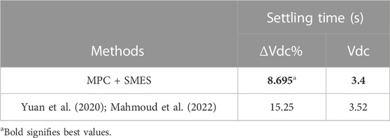
TABLE 5. Results for 0.20 pu balanced Voltage Swell conditions.
6 Conclusion
In this paper, a grid-tied PMA wind turbine with SMES connected at the dc-link. The model incorporates a wind turbine with a capacity of 1.5 MW, an SMES device, and a machine and grid-side converter.
The WECS performance was evaluated under balanced voltage sag and swell scenarios.
The 80% voltage dip experiences an overvoltage of up to 5450 V on the DC-link, while the 0.20% swell reaches 1000 V from the reference value, indicating how detrimental sags are to the dc-link capacitor.
This means that PMA wind turbines are at a higher risk from balanced voltage sags compared to balanced voltage swells. Reactive power is managed via a strategy that regulates its transfer between the grid and the converter. Reactive power flows from the grid to the converter during a swell and the other way around during a sag. This contributes to the reliability of the power system.
There is clear evidence that the suggested ride through technique improves the performance of PMA-WTG in the face of grid voltage fluctuations.
Data availability statement
The raw data supporting the conclusion of this article will be made available by the authors, without undue reservation.
Author contributions
SA: Formal Analysis, Methodology, Supervision, Writing–review and editing. EM: Conceptualization, Formal Analysis, Methodology, Resources, Validation, Writing–original draft. TM: Supervision, Writing–review and editing. WR: Data curation, Resources, Writing–review and editing. OA-R: Conceptualization, Formal Analysis, Methodology, Resources, Validation, Writing–review and editing.
Funding
The author(s) declare financial support was received for the research, authorship, and/or publication of this article. This work was supported by the Qatar National Library (QNL).
Conflict of interest
The authors declare that the research was conducted in the absence of any commercial or financial relationships that could be construed as a potential conflict of interest.
Publisher’s note
All claims expressed in this article are solely those of the authors and do not necessarily represent those of their affiliated organizations, or those of the publisher, the editors and the reviewers. Any product that may be evaluated in this article, or claim that may be made by its manufacturer, is not guaranteed or endorsed by the publisher.
References
Abdel Aleem, S. H. E., Abdelaziz, A. Y., and Zobaa, A. F. (2017). “Egyptian grid code of wind farms and power quality,” in Handbook of distributed generation: electric power technologies, economics and environmental impacts (Berlin, Germany: Springer), 227–245. doi:10.1007/978-3-319-51343-0_7
Abdel-Rahim, O., Chub, A., Vinnikov, D., and Blinov, A. (2022). DC integration of residential photovoltaic systems: a survey. IEEE Access 10, 66974–66991. doi:10.1109/ACCESS.2022.3185788
Abdel-Rahim, O., and Funato, H. (2014). “A novel model predictive control for high gain switched inductor power conditioning system for photovoltaic applications,” in Proceedings of the 2014 IEEE Innovative Smart Grid Technologies - Asia (ISGT ASIA), Kuala Lumpur, Malaysia, May, 2014, 170–174. doi:10.1109/ISGT-Asia.2014.6873784
Abdel-Rahim, O., Funato, H., Abu-Rub, H., and Ellabban, O. (2014). “Multiphase Wind Energy generation with direct matrix converter,” in Proceedings of the 2014 IEEE International Conference on Industrial Technology (ICIT), Busan, Korea (South), February, 2014, 519–523. doi:10.1109/ICIT.2014.6894994
Abhinav, R., and Pindoriya, N. M. (2016). “Grid integration of wind turbine and battery energy storage system: review and key challenges,” in Proceedings of the 2016 IEEE 6th International Conference on Power Systems, ICPS, New Delhi, India, March. 2016. doi:10.1109/ICPES.2016.7583998
Ahsan, H., and Mufti, M. ud D. (2020). Systematic development and application of a fuzzy logic equipped generic energy storage system for dynamic stability reinforcement. Int. J. Energy Res. 44 (11), 8974–8987. doi:10.1002/ER.5606
Aimene, M., Payman, A., and Dakyo, B. (2022). Comparative study between flatness-based and field-oriented control methods of a grid-connected wind energy conversion system. Process. 2022 10 (2), 378. doi:10.3390/PR10020378
Barra, P. H. A., de Carvalho, W. C., Menezes, T. S., Fernandes, R. A. S., and Coury, D. v. (2021). A review on wind power smoothing using high-power energy storage systems. Renew. Sustain. Energy Rev. 137, 110455. doi:10.1016/J.RSER.2020.110455
Benali, A., Khiat, M., Allaoui, T., and Denaï, M. (2018). Power quality improvement and low voltage ride through capability in hybrid wind-pv farms grid-connected using dynamic voltage restorer. IEEE Access 6, 68634–68648. doi:10.1109/ACCESS.2018.2878493
Chen, T., Abdel-Rahim, O., Peng, F., and Wang, H. (2020). An improved finite control set-MPC-based power sharing control strategy for islanded AC microgrids. IEEE Access 8, 52676–52686. doi:10.1109/ACCESS.2020.2980860
Dahiya, P., Sharma, V., and Naresh, R. (2019). Optimal sliding mode control for frequency regulation in deregulated power systems with DFIG-based wind turbine and TCSC–SMES. Neural Comput. Appl. 31 (7), 3039–3056. doi:10.1007/s00521-017-3250-y
Das, C. K., Bass, O., Kothapalli, G., Mahmoud, T. S., and Habibi, D. (2018). Overview of energy storage systems in distribution networks: placement, sizing, operation, and power quality. Renew. Sustain. Energy Rev. 91, 1205–1230. doi:10.1016/J.RSER.2018.03.068
De Siqueira, L. M. S., and Peng, W. (2021). Control strategy to smooth wind power output using battery energy storage system: a review. J. Energy Storage 35, 102252. doi:10.1016/J.EST.2021.102252
Djagarov, N., Grozde, Z., Enchev, G., and Djagarova, J. (2019). “Mathematical model for study of low-voltage ride through of wind permanent magnet synchronous generator by means of STATCOM,” in Proceedings of the 2019 20th International Scientific Conference on Electric Power Engineering, EPE 2019, Kouty nad Desnou, Czech Republic, May 2019. doi:10.1109/EPE.2019.8778121
Global Wind Energy Council, (2023). Global wind report 2023. Available: https://gwec.net/wp-content/uploads/2023/03/GWR-2023_interactive.pdf.
Gouda, E. A., Abd-Alaziz, A., and El-Saadawi, M. (2020). Design modeling, and control of multi-stage SMES integrated with PV system. J. Energy Storage 29, 101399. doi:10.1016/j.est.2020.101399
Hu, Y. L., Wu, Y. K., Chen, C. K., Wang, C. H., Chen, W. T., and Il Cho, L. (2017). A review of the low-voltage ride-through capability of wind power generators. Energy Procedia 141, 378–382. doi:10.1016/J.EGYPRO.2017.11.046
Huang, C., Zheng, Z., Xiao, X., and Chen, X. (2020b). Cooperative strategy of SMES device and modified control for cost-effective fault ride-through enhancement and power smoothing of 10 MW class superconducting wind turbine. J. Renew. Sustain. Energy 12 (3), 033302. doi:10.1063/1.5143565
Huang, C., Zheng, Z., Xiao, X., and Chen, X. (2020a). Enhancing low-voltage ride-through capability of PMSG based on cost-effective fault current limiter and modified WTG control. Electr. Power Syst. Res. 185, 106358. doi:10.1016/J.EPSR.2020.106358
Jannati, M., Hosseinian, S. H., Vahidi, B., and jie Li, G. (2016). ADALINE (ADAptive Linear NEuron)-based coordinated control for wind power fluctuations smoothing with reduced BESS (battery energy storage system) capacity. Energy 101, 1–8. doi:10.1016/j.energy.2016.01.100
Jiang, P., van Fan, Y., and Klemeš, J. J. (2021). Impacts of COVID-19 on energy demand and consumption: challenges, lessons and emerging opportunities. Appl. Energy 285, 116441. doi:10.1016/J.APENERGY.2021.116441
Joseph, S. B., Dada, E. G., Abidemi, A., Oyewola, D. O., and Khammas, B. M. (2022). Metaheuristic algorithms for PID controller parameters tuning: review, approaches and open problems. Heliyon 8 (5), e09399. doi:10.1016/J.HELIYON.2022.E09399
Kim, C., and Kim, W. (2021). Low-voltage ride-through coordinated control for pmsg wind turbines using de-loaded operation. IEEE Access 9, 66599–66606. doi:10.1109/ACCESS.2021.3076787
López, J., Gubía, E., Olea, E., Ruiz, J., and Marroyo, L. (2009). Ride through of wind turbines with doubly fed induction generator under symmetrical voltage dips. IEEE Trans. Industrial Electron. 56 (10), 4246–4254. doi:10.1109/TIE.2009.2028447
Luo, X., Wang, J., Wojcik, J., Wang, J., and Draganescu, M., (2018). Review of voltage and frequency grid code specifications for electrical energy storage applications. Energies 11 (5), 1070. doi:10.3390/EN11051070
Lyu, J., Ma, B., Yan, H., Ji, Z., and Ding, J. (2020). A modified finite control set model predictive control for 3L−NPC Grid−Connected inverters using virtual voltage vectors. J. Electr. Eng. Technol. 15 (1), 121–133. doi:10.1007/s42835-019-00305-8
Mahmoud, M. M., Aly, M. M., Salama, H. S., and Abdel-Rahim, A.-M. M. (2022). An internal parallel capacitor control strategy for DC-link voltage stabilization of PMSG-based wind turbine under various fault conditions. Wind Eng. 46 (3), 983–992. doi:10.1177/0309524X211060684
Makhad, M., Zazi, K., Zazi, M., and Loulijat, A. (2022). Adaptive super-twisting terminal sliding mode control and LVRT capability for switched reluctance generator based wind energy conversion system. Int. J. Electr. Power & Energy Syst. 141, 108142. doi:10.1016/J.IJEPES.2022.108142
Morgan, E. F., Abdel-Rahim, O., Megahed, T. F., Suehiro, J., and Abdelkader, S. M. (2022a). Fault ride-through techniques for permanent magnet synchronous generator wind turbines (PMSG-WTGs): a systematic literature review. Energies 15 (23), 9116. doi:10.3390/EN15239116
Morgan, E. F., Megahed, T. F., Suehiro, J., and Abdelkader, S. M. (2022b). A Fault Ride-Through technique for PMSG wind turbines using superconducting magnetic energy storage (SMES) under grid voltage sag conditions. Renew. Energy Power Qual. J. 20, 79–83. doi:10.24084/REPQJ20.223
Mukherjee, P., and Rao, V. v. (2019). Superconducting magnetic energy storage for stabilizing grid integrated with wind power generation systems. J. Mod. Power Syst. Clean Energy 7 (2), 400–411. doi:10.1007/s40565-018-0460-y
Nasiri, M., and Arzani, A. (2022). Robust control scheme for the braking chopper of PMSG-based wind turbines–A comparative assessment. Int. J. Electr. Power & Energy Syst. 134, 107322. doi:10.1016/J.IJEPES.2021.107322
Nielsen, K. E., and Molinas, M. (2010). “Superconducting Magnetic Energy Storage (SMES) in power systems with renewable energy sources,” in Proceedings of the 2010 IEEE International Symposium on Industrial Electronics, Bari, Italy, July, 2010, 2487–2492. doi:10.1109/ISIE.2010.5637892
Nikolaidis, P., and Poullikkas, A. (2018). Cost metrics of electrical energy storage technologies in potential power system operations. Sustain. Energy Technol. Assessments 25, 43–59. doi:10.1016/J.SETA.2017.12.001
Okedu, K. E. (2022). Improving the performance of pmsg wind turbines during grid fault considering different strategies of fault current limiters. Front. Energy Res. 10. doi:10.3389/fenrg.2022.909044
Qais, M. H., Hasanien, H. M., Alghuwainem, S., and Elgendy, M. A. (2019). “Output power smoothing of grid-tied pmsg-based variable speed wind turbine using optimal controlled SMES,” in Proceedings of the 2019 54th International Universities Power Engineering Conference, Bucharest, Romania, September. 2019. doi:10.1109/UPEC.2019.8893530
Qais, M. H., Hasanien, H. M., and Alghuwainem, S. (2020a). Output power smoothing of wind power plants using self-tuned controlled SMES units. Electr. Power Syst. Res. 178, 106056. doi:10.1016/J.EPSR.2019.106056
Qais, M. H., Hasanien, H. M., and Alghuwainem, S. (2020b). Whale optimization algorithm-based Sugeno fuzzy logic controller for fault ride-through improvement of grid-connected variable speed wind generators. Eng. Appl. Artif. Intell. 87, 103328. doi:10.1016/j.engappai.2019.103328
Raouf, A., Tawfiq, K. B., Tag Eldin, E., Youssef, H., and E El-Kholy, E. (2023). Wind energy conversion systems based on a synchronous generator: comparative review of control methods and performance. Energies 16 (5), 2147. doi:10.3390/en16052147
Sarkar, M. N. I., Meegahapola, L. G., and Datta, M. (2018). Reactive power management in renewable rich power grids: a review of grid-codes, renewable generators, support devices, control strategies and optimization Algorithms. IEEE Access 6, 41458–41489. doi:10.1109/ACCESS.2018.2838563
Soliman, M. A., Hasanien, H. M., Al-Durra, A., and Alsaidan, I. (2020). A novel adaptive control method for performance enhancement of grid-connected variable-speed wind generators. IEEE Access 8, 82617–82629. doi:10.1109/ACCESS.2020.2991689
Wang, D., Gao, X., Meng, K., Qiu, J., Lai, L. L., and Gao, S. (2018). Utilisation of kinetic energy from wind turbine for grid connections: a review paper. IET Renew. Power Gener. 12 (6), 615–624. doi:10.1049/iet-rpg.2017.0590
Xu, L., Lin, R., Ding, L., Zhang, H., Li, S., and Huang, C. (2019). A new frt method of pmsg under grid faults by using improved msc control and smes device. IOP Conf. Ser. Mater Sci. Eng. 490 (7), 072032. doi:10.1088/1757-899X/490/7/072032
Yuan, L., Meng, K., Huang, J., Dong, Z. Y., Zhang, W., and Xie, X. (2020). Development of HVRT and LVRT control strategy for PMSG-based wind turbine generators. Energies 13, 5442–5520. doi:10.3390/en13205442
Keywords: fault ride-through, grid faults, model predictive control, permanent magnet synchronous generators, wind energy
Citation: Abdelkader SM, Morgan EF, Megahed TF, Rohouma W and Abdel-Rahim O (2023) A model predictive control strategy for enhancing fault ride through in PMSG wind turbines using SMES and improved GSC control. Front. Energy Res. 11:1277954. doi: 10.3389/fenrg.2023.1277954
Received: 15 August 2023; Accepted: 09 October 2023;
Published: 25 October 2023.
Edited by:
Joshuva Arockia Dhanraj, Hindustan Institute of Technology and Science, IndiaReviewed by:
Kenneth E. Okedu, Melbourne Institute of Technology, AustraliaAngalaeswari S., Vellore Institute of Technology (VIT), India
Copyright © 2023 Abdelkader, Morgan, Megahed, Rohouma and Abdel-Rahim. This is an open-access article distributed under the terms of the Creative Commons Attribution License (CC BY). The use, distribution or reproduction in other forums is permitted, provided the original author(s) and the copyright owner(s) are credited and that the original publication in this journal is cited, in accordance with accepted academic practice. No use, distribution or reproduction is permitted which does not comply with these terms.
*Correspondence: Wesam Rohouma, d2VzYW0ucm9ob3VtYUB1ZHN0LmVkdS5xYQ==; Omar Abdel-Rahim, by5hYmRlbHJhaGltQGFzd3UuZWR1LmVn