 Yang Liu
 Pingping Xie
- Power Dispatch and Control Center, Guangdong Power Grid Company Lmt., Guangzhou, China
Recently, the power systems with a high penetration of renewables and power electronics have come into being. In these power systems, complex system dynamics, emergency faults, and insufficient frequency regulation reserve pose threats to system frequency stability. Based on the clustering development of energy storage, to ensure the system frequency stability when emergency faults occur, this paper proposes a decentralized frequency emergency control (FEC) strategy considering the participation of energy storage clusters (ESCs). First, the overall framework of the optimal-droop-based FEC strategy is introduced, which achieves the coordination between FEC and conventional frequency regulation strategies. Second, to appropriately allocate the unbalanced power among the generators and ESCs, a general design method for optimal droop coefficients is proposed, which is applicable to various control objectives. The optimality of the droop coefficients is rigorously proven. This case study is carried out on an electromagnetic transient simulation platform, and the simulation results verify the effectiveness and optimality of the proposed FEC strategy.
1 Introduction
With the vigorous development of renewable energy generation and the integration of a large number of power electronic devices [such as high-voltage direct current (HVDC) transmission systems], the power systems with a high penetration of renewables and power electronics have come into being (Xu et al., 2022; Yang et al., 2022; Zhu et al., 2022). In such power systems, the complex system dynamics have brought new challenges to the system operation and control (Pillai et al., 2020; Yang et al., 2021a). This paper focuses on the frequency control in the power systems with a high penetration of renewables and power electronics. On one hand, the emergency faults (e.g., HVDC blocking faults) are prone to occur in the power systems with a high penetration of renewables and power electronics, which will cause considerable unbalanced power and seriously threaten the system frequency stability. On the other hand, due to the integration of a large number of power electronic devices, the frequency regulation reserve and the inertia level of the power systems are insufficient, which cannot meet the frequency regulation requirements in case of emergency faults (Lyu et al., 2021; Zhang et al., 2023). Therefore, in the power systems with a high penetration of renewables and power electronics, the conventional frequency regulation strategies might not ensure system frequency stability, and frequency emergency control (FEC) strategies are urgently required.
Traditional FEC strategies in power systems mainly include generator-tripping strategies and load-shedding strategies. However, the above strategies usually cause serious economic losses (Song et al., 2016; Li et al., 2020; Darbandsari and Amraee, 2022). In recent years, energy storage technology has been developing rapidly, which effectively promotes the integration of renewable energy generation and facilitates the secure and stable operation of power systems. Considering the clustering development of energy storage, multiple energy storage systems within a certain region can be regarded as an energy storage cluster (ESC). In the transmission network, an ESC equivalently performs as energy storage with fairly large capacity and strong regulation ability. Therefore, if the cluster energy storage is able to participate in the frequency emergency control of the power system, system frequency stability can effectively be improved (Teixeira and Carmen, 2020; Zhang et al., 2021). However, currently, there is no research basis about the frequency emergency control considering the participation of ESCs, and the following issues need to be solved: (i) In which way (centralized, distributed, or decentralized) can the ESCs participate in FEC? (ii) How to reasonably allocate the unbalanced power among multiple ESCs for fairness consideration? (iii) How to coordinate FEC and the conventional frequency regulation strategies? This paper aimed to address the above issues.
Currently, there is no research about the FEC design considering the participation of ESCs in the existing literature. However, if ESCs are regarded as one kind of flexible frequency regulation resources (flexible frequency regulation resources include renewable energy generation systems and HVDC transmission systems), there are studies being carried out to utilize the short-time overload capability of HVDC transmission systems to provide frequency emergency support for power systems. Xu et al. (2015) proposed a response-based FEC method for AC–DC hybrid systems, which outputs the DC power emergency control order based on the real-time response characteristics of the power system operation. However, the FEC strategy in the the work of Xu et al. (2015) is a centralized strategy. On one hand, the centralized control strategy requires a control center to collect system global information, calculate the control commands, and send the commands to the local control units; thus, the centralized control strategy has high requirements for the efficiency and reliability of the communication system. On the other hand, the single-point faults are prone to occur when adopting the centralized control strategy, which might cause control mismatch when emergency faults occur. Therefore, the decentralized control logic that does not require communication among control units is more appropriate when designing FEC strategies. Torres L. et al. (2014) and He et al. (2023) proposed the decentralized virtual-synchronous machine (VSG)-based control strategy for energy storage, which enables energy storage to provide both frequency and inertia support for the power systems. However, the control strategy in the work of Torres L. et al. (2014) and He et al. (2023) is a proportional-integral-derivative (PID)-type control, and the control parameter selection of the PID-type control usually relies on subjective judgment and practical engineering experience, which makes it difficult to optimize the control parameters. Droop control is a type of decentralized control logic that is easy to optimize the parameters and has wide applications in engineering practices. Hence, if the droop control is utilized for the FEC design, the unbalanced power can be reasonably distributed by the optimal selection of the droop coefficients. Han et al. (2023) proposed a joint cooperative frequency control method for multiple energy storage systems based on the droop control, which selects the droop coefficients by the centralized estimation of the maximal frequency deviation and realizes the power allocation among multiple energy storage systems. Li et al. (2021) proposed a primary frequency regulation strategy for energy storage based on dynamic droop coefficients and dynamic set-point of the state of charge (SoC), which adaptively adjusts the droop coefficients according to the real-time SoC of energy storage. Both the centralized optimization of droop coefficients and the adaptive droop design is carried out for a single control objective. However, in engineering practice, different control objectives are usually selected according to the actual operating conditions; thus, it is of vital significance to study the unified droop coefficient optimization method that can be applied to a variety of control objectives.
In summary, in order to enable ESCs to participate in the FEC of power systems in a decentralized manner, this paper proposes a decentralized FEC strategy based on the optimal droop. First, the overall scheme of the optimal-droop-based FEC is proposed to realize the cooperative participation of the ESCs and the synchronous generators in the control process. Then, in order to reasonably allocate the unbalanced power among multiple control units, a unified construction method of the optimal control problem is proposed by selecting two different typical control objectives in engineering practice, and the analytical expressions of the optimal droop coefficients are provided. Furthermore, the optimality of the droop coefficients is proven rigorously.
The subsequent sections of this paper are organized as follows: Section 2 introduces the state-space modeling of the power system with ESCs. Section 3 introduces the overall scheme of the optimal-droop-based FEC, formulates the optimal control problem, provides the expression of the optimal droop coefficient, and rigorously proves the optimality. Section 4 builds a test power system with ESCs based on the electromagnetic transient (EMT) simulation platform and verifies the effectiveness and optimality of the proposed FEC strategy. Section 5 provides the conclusion to this paper.
2 Modeling
This section introduces the power system model with ESCs. Figure 1 shows the system topology, where
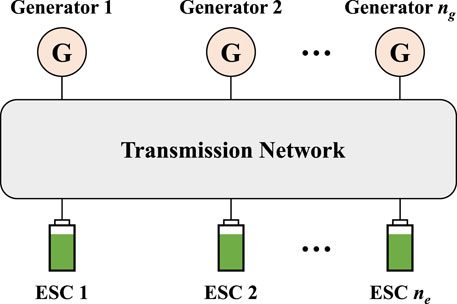
FIGURE 1. Topology of the power system with ESCs.
From the perspective of graph theory, the power system with ESCs can be represented as a graph
where
3 Frequency emergency control design
In this section, the overall scheme of the optimal-droop-based FEC is provided first. Then, the optimal control problem is formulated, the design method of optimal droop coefficients is introduced, and the optimality of the droop coefficients is rigorously proven. Moreover, the engineering deployment scheme of the designed control strategy in the power system with ESCs is provided.
3.1 Overall control scheme
Based on the practical engineering needs, the FEC strategy considering the participation of ESCs should meet the following three requirements: (i) Since the designed control strategy mainly deals with emergency faults, ESCs should only work in the case of emergency faults and not participate in the conventional frequency control (e.g., primary frequency regulation). (ii) In order to enable ESCs to respond quickly and reliably to emergency faults, the FEC strategy should be designed as a decentralized strategy that does not require communication among control units. (iii) In order to reasonably distribute the unbalanced power among multiple control units during control process, the control parameters should be optimally selected to meet certain control objectives (e.g., the two control objectives selected in Section 3.2).
According to the above three requirements, this paper adopts the decentralized droop control idea to design the frequency emergency control strategy. We assume that ESCs and the generators can provide enough power support to deal with the unbalanced power, and so, the load-shedding strategies are not considered. The overall scheme of the optimal-droop-based FEC strategy is shown in Figure 2, which mainly comprises three parts. Since ESCs do not participate in conventional primary frequency regulation, the ESC droop control and the primary frequency control are independent of each other, and the control scheme shown in Figure 2 should be designed to make the ESC droop control to work as a supplementary support for primary frequency control in emergency situations.
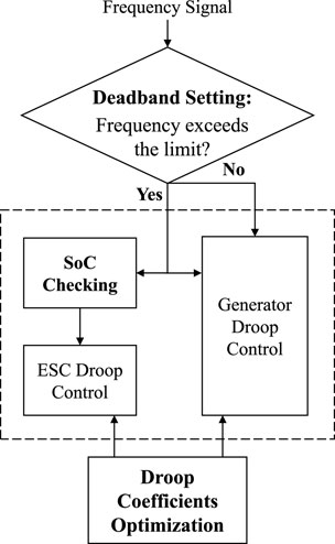
FIGURE 2. Framework of the optimal-droop-based FEC.
3.1.1 Deadband setting
When a fault occurs and causes the system frequency to change, the deadband setting is used to determine whether it is an emergency fault and whether the droop control of ESCs needs to be enabled. There are two commonly used deadband setting methods, namely, the frequency deviation limitation and the frequency change rate limitation. This paper adopts the frequency deviation limitation method. Considering frequency drops in the transmission network, the system operator would like to utilize the ESC power support instead of the load-shedding strategies to deal with emergency faults. Thus, the frequency limitation value of the deadband is supposed to be higher than the trigger value of the load-shedding strategies.
3.1.2 SoC checking
If it is necessary to enable the droop control of ESCs, SoC checking is further performed for each ESC. If the SoC of an ESC is lower than a certain threshold, the droop control of that ESC is blocked.
3.1.3 Droop coefficient optimization
In order to achieve a reasonable distribution of the unbalanced power among multiple ESCs and multiple synchronous generators, the droop coefficients of the ESCs and synchronous generators are optimized cooperatively. The formulation of the specific optimization problem and the optimal droop coefficients are described in detail in Section 3.2 and Section 3.3, respectively.
3.2 Problem formulation
In the FEC process, in order to reasonably distribute the unbalanced power among multiple ESCs and multiple synchronous generators, the optimal droop coefficients are obtained by formulating the optimal frequency emergency control problem. The optimization objective of the optimal frequency emergency control problem is to minimize the defined control cost. In the following, the two typical control objectives were selected to illustrate the general formulation method of the optimal frequency emergency control (OFC) problem.
3.2.1 Control objective I
ESC with a larger power regulation margin (PRM) provides more emergency power support. Let
where
where
3.2.2 Control objective II
ESC with larger SoC provides more emergency power support. The cost function of the generator is still as shown in Eq. 5. For each ESC, in order to make the ESC with larger SoC provide more emergency power support, the control cost of ESC i under control objective II is defined as follows:
where
In engineering practice, a variety of control objectives are usually considered comprehensively. For example, if the above two control objectives need to be considered in FEC, the above two control costs is weighted, and the control cost of ESC i is
where
When considering both control objective I and control objective II, the OFC problem is shown as follows:
where the constraint represents the power balance constraint of the entire power system. Based on the OFC problem shown in Eq. 9, the next section presents the optimal droop coefficient design method.
3.3 Optimal droop coefficients
Since the OFC problem shown in Eq. 9 is strictly convex, there exists at most one global optimal solution and no suboptimal solution. We assume that the OFC problem shown in Eq. 9 is feasible; then, the optimal droop coefficients of the generators and ESCs are analytically expressed as follows:
Furthermore, the design idea of the optimal droop coefficients is illustrated; i.e., when the optimal droop coefficients shown in Eq. 10 are adopted, the closed-loop system dynamics are equivalent to the partial primal-dual algorithm which solves the OFC problem shown in Eq. 9. Let
From Eq. 9, the objective function of the dual OFC problem is (Boyd, Boyd, and Vandenberghe, 2004)
where
According to Eqs 13 and 14, the dual variable
The dual OFC problem (DOFC) is expressed as follows:
The Lagrangian function of the DOFC problem is
where
where
3.4 Optimality analysis
This section proves the optimality of the droop coefficients in Eq. 10 rigorously. Since the OFC problem (Eq. 9) is a strictly convex optimization problem and the constraints are all linear, the Karush–Kuhn–Tucker (KKT) conditions can describe the optimal solution of the optimization problem (Shen et al., 2017; Yang et al., 2021b). We choose the phase angle of bus 1 as the reference phase angle, and the relative phase angle is defined as
Let
Then, we have the following theorem about the optimality.
Theorem 1. When the droop coefficients (Eq. 10) are adopted, if
Proof: To prove Theorem 1, we only need to show that the KKT conditions of the OFC problem are satisfied at the equilibrium point of the closed-loop system (Eqs 1–4). When at the equilibrium point, we have
where
Therefore, the stationary conditions of KKT conditions are satisfied (M. Li, 2019). Furthermore, by substituting
Thus, the feasibility conditions of KKT conditions are also satisfied. In summary, KKT conditions are satisfied at the equilibrium point of the closed-loop system, and the corresponding
3.5 Control implementation
The implementation scheme of the optimal-droop-based FEC strategy in the ESC system is shown in Figure 3.
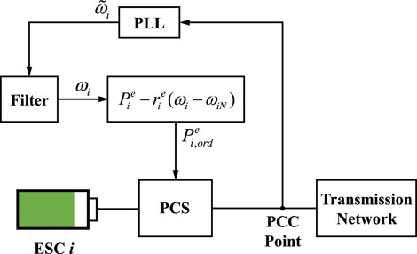
FIGURE 3. Control implementation in the ESC system.
At the droop control layer, the frequency signal at the grid-connected point is first measured by the phase-locked loop (PLL), and then, the frequency signal is input into the droop controller through the filter. The droop controller outputs the power control command for ESC. At the ESC control layer, the power control of ESC is mainly realized by the power conversion system (PCS), which is usually comprised of the DC–AC bidirectional converter and the control unit. The PCS is connected between the battery system and the power grid and realizes the bidirectional power conversion, which makes the ESC system have a constant power control mode, constant power factor control mode, and constant current control mode. Therefore, when the constant power control mode is adopted, ESC can realize rapid power regulation, according to the power control command from the droop controller, and provide emergency power support.
4 Case study
4.1 Test system
This section verifies the effectiveness and optimality of the proposed FEC strategy. A test system with ESCs is built on the electromagnetic transient (EMT) simulation platform, and the topology of the test system is shown in Figure 4. In this test system, the AC transmission network adopts the IEEE 39-bus system, which contains seven generators and is connected to three ESCs (ESC1, ESC2, and ESC3). The proposed optimal-droop-based FEC strategy is implemented in ESCs, and the generators adopt the primary droop control.
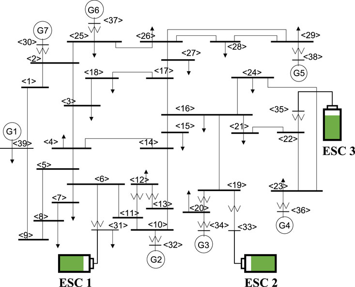
FIGURE 4. Topology of the test system.
Let the active power base-value of the test system be
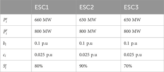
TABLE 1. Parameters of ESCs.
Based on the above parameter settings, the optimal droop coefficients can be obtained, according to Eq. 10. It should be noted that in order to reflect the control effect of the FEC strategy under two control objectives, the two control objectives are verified separately in the subsequent case analysis; i.e., when adopting control objective I,
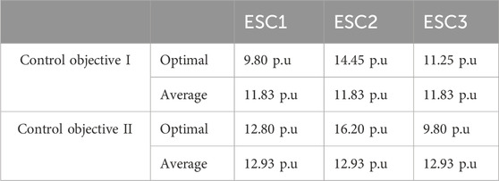
TABLE 2. Optimal/average droop coefficients of ESCs.
We set a
4.2 Effectiveness verification
First, the effectiveness of the FEC strategy considering the participation of ESCs is verified. We set two groups of simulations: (i) ESCs have no droop control. (ii) ESCs are implemented with droop control, and the droop coefficients are the optimal droop coefficients under control objective I. The system frequencies in the two groups of simulations are shown in Figure 5, and the active power of ESCs is shown in Figure 6.

FIGURE 5. Frequency of the test system.
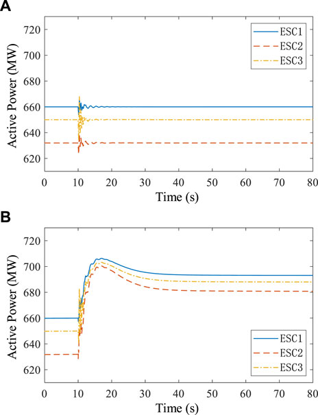
FIGURE 6. Active power of ESCs. (A) ESC without a droop control. (B) ESC with a droop control.
According to Figure 5, it can be seen that when ESCs have no droop control, after the emergency fault occurs, the steady-state frequency of the system is lower than 49.8 Hz, and the frequency overshoot is large, which would have caused serious frequency instability in practical engineering. When ESCs are implemented with the designed optimal droop control, after the emergency fault occurs, the steady-state frequency of the system is higher than 49.8 Hz, and the frequency overshoot is small. Therefore, the FEC strategy, considering the participation of ESCs, can effectively enhance the frequency stability of the power system and can improve the steady-state and transient characteristics of the system frequency response.
Furthermore, as shown in Figure 6A, since ESCs have no droop control, after the emergency fault occurs, the steady-state active power of ESCs remains unchanged. Figure 6B shows that the power of ESCs is rapidly increasing under the effect of the droop control, which effectively supports the system frequency after the emergency fault. The above results verify the effectiveness of the FEC strategy, considering the participation of the ESCs.
4.3 Optimality verification
This section verifies the optimality of the FEC control strategy. For the two control objectives, let the ESCs adopt the optimal droop coefficients and the average droop coefficients, respectively. Under the same emergency fault setting, the active power of ESCs is output to verify the control objectives. The active power of ESCs under control objective I is shown in Figure 7, and the active power of ESCs under control objective II is shown in Figure 8.
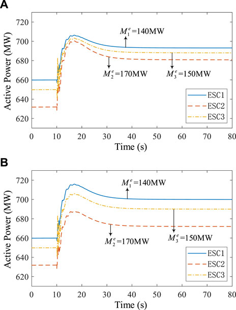
FIGURE 7. Active power of ESCs under control objective I. (A) Optimal droop coefficients. (B) Average droop coefficients.
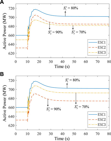
FIGURE 8. Active power of ESCs under control objective II. (A) Optimal droop coefficients. (B) Average droop coefficients.
According to Figure 7, since the active power upper bounds of the three ESCs are set to be the same, the power regulation margins of the three ESCs satisfy
As shown in Figure 8, when considering control objective II, the SoC of the three ESCs satisfy
5 Conclusion
In this paper, a decentralized FEC strategy considering the participation of ESCs is proposed to effectively ensure the frequency stability of the power systems with a high penetration of renewables and power electronics. First, an overall scheme of the optimal-droop-based FEC strategy is proposed, in which the deadband setting realizes the coordination between the FEC strategy and the conventional frequency regulation measures. Then, in order to reasonably allocate the unbalanced power among multiple ESCs and multiple generators, a unified design method for optimal droop coefficients is proposed based on two typical control objectives. The optimal frequency emergency control problem is formulated, and the optimal droop coefficients are obtained analytically. Furthermore, the optimality of the droop coefficients is rigorously proven based on KKT conditions, and the implementation scheme of the proposed FEC strategy in engineering practice is provided. In this case study, a full EMT simulation model of a power system with ESCs is built, and the simulation results verify the effectiveness and optimality of the proposed FEC strategy.
Considering the future extensions of this paper, the FEC strategy with the participation of multiple flexible frequency regulation resources is suggested to be studied, and the coordination mechanism of multiple energy storage systems within one ESC when participating in the FEC strategy should be investigated further.
Data availability statement
The raw data supporting the conclusion of this article will be made available by the authors, without undue reservation.
Author contributions
YL: conceptualization, formal analysis, methodology, software, writing–original draft, and writing–review and editing. PX: conceptualization, methodology, and writing–review and editing. GW: conceptualization, formal analysis, and writing–review and editing. YC: formal analysis, software, and writing–review and editing. XL: investigation, methodology, and writing–review and editing. QL: conceptualization, funding acquisition, supervision, and writing–review and editing.
Funding
The authors declare that financial support was received for the research, authorship, and/or publication of this article. This work was supported by the Science and Technology Project of China Southern Power Grid [03600KK52200049 (GDKJXM20201978)].
Conflict of interest
Authors YL, PX, GW, YC, XL, and QL were employed by Guangdong Power Grid Company Ltd.
Publisher’s note
All claims expressed in this article are solely those of the authors and do not necessarily represent those of their affiliated organizations, or those of the publisher, the editors, and the reviewers. Any product that may be evaluated in this article, or claim that may be made by its manufacturer, is not guaranteed or endorsed by the publisher.
References
Boyd, S., Boyd, S. P., and Vandenberghe, L. (2004). Convex optimization. Cambridge University Press.
Darbandsari, A., and Amraee, T. (2022). Under frequency load shedding for low inertia grids utilizing smart loads. Int. J. Electr. Power & Energy Syst. 135 (February), 107506. doi:10.1016/j.ijepes.2021.107506
Han, H., Li, Q., and Lv, Z. (2023). A coordinated frequency modulation method based on adaptive selection of droop coefficient for multiple energy storage combined voltage sources. Power Syst. Clean Energy 39 (3), 116–125.
He, P., Zhao, L., Jin, H., Zhao, C., Fan, J., and Wu, X. (2023). An adaptive VSG control strategy of battery energy storage system for power system frequency stability enhancement. Int. J. Electr. Power & Energy Syst. 149 (July), 109039. doi:10.1016/j.ijepes.2023.109039
Kundur, P., J Balu, N., and Lauby, M. G. (1994). Power system stability and control, 7. New York: McGraw-Hill.
Li, C., Wu, Y., Sun, Y., Zhang, H., Liu, Y., Liu, Y., et al. (2020). Continuous under-frequency load shedding scheme for power system adaptive frequency control. IEEE Trans. Power Syst. 35 (2), 950–961. doi:10.1109/tpwrs.2019.2943150
Li, J., Gao, Z., Hong, Y., Lin, L., Shen, B., and Fan, X. (2021). Primary frequency regulation control strategy of energy storage based on dynamic droop coefficient and SOC reference. Power Syst. Prot. Control 49 (5), 1–10. doi:10.19783/j.cnki.pspc.200472
Li, M. (2019). Generalized Lagrange multiplier method and KKT conditions with an application to distributed optimization. IEEE Trans. Circuits Syst. II Express Briefs 66 (2), 252–256. doi:10.1109/tcsii.2018.2842085
Lyu, X., Jia, Y., and Dong, Z. (2021). Adaptive frequency responsive control for wind farm considering wake interaction. J. Mod. Power Syst. Clean Energy 9 (5), 1066–1075. doi:10.35833/mpce.2020.000237
Pillai, A. G., Rita Samuel, E., and Unnikrishnan, A. (2020). Optimal load frequency control through combined state and control gain estimation for noisy measurements. Prot. Control Mod. Power Syst. 5 (1), 24–12. doi:10.1186/s41601-020-00169-5
Shen, X., Zhang, Y., Shen, T., and Khajorntraidet, C. (2017). Spark advance self-optimization with knock probability threshold for lean-burn operation mode of SI engine. Energy 122, 1–10. doi:10.1016/j.energy.2017.01.065
Song, Z., Lin, Y., Liu, C., Ma, Z., and Ding, L. (2016). “Review on over-frequency generator tripping for frequency stability control,” in 2016 IEEE PES Asia-Pacific Power and Energy Engineering Conference (APPEEC), Xi'an, 25-28 October 2016, 2240–2243.
Teixeira, T. P., and Carmen, L. T. B. (2020). Operation strategies for coordinating battery energy storage with wind power generation and their effects on system reliability. J. Mod. Power Syst. Clean Energy 9 (1), 190–198. doi:10.35833/MPCE.2019.000492
Torres, L., Miguel, A., Luiz, A. C., Lopes, L. A., Morán, T., José, R., et al. (2014). Self-tuning virtual synchronous machine: a control strategy for energy storage systems to support dynamic frequency control. IEEE Trans. Energy Convers. 29 (4), 833–840. doi:10.1109/tec.2014.2362577
Wang, Z., Liu, F., Low, S. H., Zhao, C., and Mei, S. (2017). Distributed frequency control with operational constraints, Part I: per-node power balance. IEEE Trans. Smart Grid 10 (1), 40–52. doi:10.1109/tsg.2017.2731810
Wood, A. J., Bruce, F. W., and Sheblé, G. B. (2013). Power generation, operation, and control. John Wiley & Sons.
Xu, B., Zhang, G., Li, K., Li, B., Chi, H., Yao, Y., et al. (2022). Reactive power optimization of a distribution network with high-penetration of wind and solar renewable energy and electric vehicles. Prot. Control Mod. Power Syst. 7 (1), 51. doi:10.1186/s41601-022-00271-w
Xu, S., Wu, P., Zhao, B., Sun, H., Yi, J., Chen, Z., et al. (2015). Coordinated control strategy of interconnected grid integrated with UHVDC transmission line from hami to zhengzhou. Power Syst. Technol. 39 (07), 1773–1778. doi:10.13335/j.1000-3673.pst.2015.07.002
Yang, N., Dong, Z., Wu, L., Zhang, L., Shen, X., Chen, D., et al. (2021a). A comprehensive review of security-constrained unit commitment. J. Mod. Power Syst. Clean Energy 10 (3), 562–576. doi:10.35833/mpce.2021.000255
Yang, N., Qin, T., Wu, L., Huang, Y., Huang, Y., Xing, C., et al. (2022). A multi-agent game based joint planning approach for electricity-gas integrated energy systems considering wind power uncertainty. Electr. Power Syst. Res. 204, 107673. doi:10.1016/j.epsr.2021.107673
Yang, N., Yang, C., Wu, L., Shen, X., Jia, J., Li, Z., et al. (2021b). Intelligent data-driven decision-making method for dynamic multisequence: an E-seq2seq-based SCUC expert system. IEEE Trans. Industrial Inf. 18 (5), 3126–3137. doi:10.1109/tii.2021.3107406
Yang, P., Liu, F., Wang, Z., and Shen, C. (2019). Distributed stability conditions for power systems with heterogeneous nonlinear bus dynamics. IEEE Trans. Power Syst. 35 (3), 2313–2324. doi:10.1109/tpwrs.2019.2951202
Zhang, C., Liu, L., Cheng, H., Liu, D., Zhang, J., and Li, G. (2021). Frequency-constrained Co-planning of generation and energy storage with high-penetration renewable energy. J. Mod. Power Syst. Clean Energy 9 (4), 760–775. doi:10.35833/mpce.2020.000743
Zhang, Y., Le, W., Fu, W., Chen, X., and Hu, S. (2023). Secondary frequency control strategy considering DoS attacks for MTDC system. Electr. Power Syst. Res. 214, 108888. doi:10.1016/j.epsr.2022.108888
Keywords: frequency emergency control, energy storage cluster, droop control, optimal control, power system
Citation: Liu Y, Xie P, Wu G, Chen Y, Lin X and Lu Q (2024) Frequency emergency control strategy in power systems considering the participation of energy storage clusters. Front. Energy Res. 12:1355344. doi: 10.3389/fenrg.2024.1355344
Received: 13 December 2023; Accepted: 20 February 2024;
Published: 05 March 2024.
Edited by:
Nan Yang, China Three Gorges University, ChinaCopyright © 2024 Liu, Xie, Wu, Chen, Lin and Lu. This is an open-access article distributed under the terms of the Creative Commons Attribution License (CC BY). The use, distribution or reproduction in other forums is permitted, provided the original author(s) and the copyright owner(s) are credited and that the original publication in this journal is cited, in accordance with accepted academic practice. No use, distribution or reproduction is permitted which does not comply with these terms.
*Correspondence: Yang Liu, bGl1eWFuZ0BnZGRkLmNzZy5jbg==