 Gaojie Liu
 Aoyu Xu
 Yongqiang Wang
 Qin Lou
- 1School of Energy and Power Engineering, University of Shanghai for Science and Technology, Shanghai, China
- 2Shanghai Key Laboratory of Multiphase Flow and Heat Transfer for Power Engineering, Shanghai, China
Introduction: This study investigates the displacement of two miscible fluids within an inclined porous medium at the pore scale, highlighting how the pore-scale microstructure, inclination angle, and viscosity ratio affect the interfacial instability between two fluids during displacement processes.
Methods: The lattice Boltzmann Method (LBM) is employed to solve the governing equations. Two distribution functions are used to simulate the velocity field and the concentration field, respectively.
Results and discussion: An increase in inclination angle exacerbates the interfacial instability between fluids and the viscous fingering phenomenon. This viscous fingering expands the sweep range of displacing fluids, which improves the displacement efficiency. When θ > 50°, further increase in inclination angle will not cause significant changes in displacement efficiency. In addition, the viscosity ratio is a key factor affecting displacement efficiency. The larger the viscosity ratio, the greater the displacement efficiency. Furthermore, the critical viscosity ratio has been found, and any increase in the viscosity ratio above the critical value will not affect the displacement efficiency.
1 Introduction
Developing energy storage systems or technologies can provide long-term support for future low-carbon energy systems while reducing energy supply risk. At present, the main energy storage technology is pumped hydro energy storage (Rehman et al., 2015; Javed et al., 2020), and the research and application of phase change energy storage (Yang et al., 2020; Huo et al., 2022; Yang et al., 2022; Liu et al., 2023a), battery energy storage (Heyhat et al., 2020; Naghavi Sanjani et al., 2023) and other energy storage technologies are developing (Koohi-Fayegh and Rosen, 2020; Liu et al., 2023c). However, the energy storage technologies mentioned above are still unable to meet the demands for big capacity and long-term energy storage. Meanwhile, underground energy storage (Strobel et al., 2020; Zivar et al., 2021) can serve as both energy transmission and storage in the energy market, and it is a viable solution to the problem of big-capacity long-term energy storage.
Hydrogen energy (Lackey et al., 2023; Zhang et al., 2023) is an excellent solution to the problem of energy sustainability, with advantages such as a large number of sources, a high calorific value, no pollution, and a wide range of applications. Hydrogen has a lower molecular weight than natural gas, hence it requires more space and better sealing. Reservoir rocks, as a result, provide a conducive environment for large-scale hydrogen energy storage and are potential hydrogen storage sites (Lankof and Tarkowski, 2020). The process of underground hydrogen storage is extremely complicated because it involves the interaction of fluid flow with heat and mass transfer in porous media. One common issue in porous media is miscible displacement.
Miscible displacement refers to the displacement of two or more miscible fluids, such as seawater and freshwater, surface sewage and groundwater, tracer-containing fluids and pure fluids, supercritical carbon dioxide and crude oil, which are widely used in the fields of hydrology (Tosco et al., 2014), chemistry, medicine, and petroleum engineering (Jia et al., 2019; Bashir et al., 2022). Due to the differences in the pore structure characteristics (connectivity, tortuosity, etc.) and fluid flow characteristics (viscosity ratio of displacing fluid and displaced fluid, molecular diffusion, displacement flow rate, etc.) of porous media, fingering instabilities often occur during miscible displacement. When a less viscous fluid is intruded into a more viscous fluid, the interface between them can become unstable, resulting in viscous fingering (Saffman and Taylor, 1958). The main focus of this investigation is on the viscous fingering in the miscible displacement process.
The viscous fingering phenomenon has been extensively studied over the past several decades (Homsy, 1987; Bacri et al., 1991; Liu et al., 2023b), with the majority of the study being done at the representative elementary volume (REV) scale (Zimmerman and Homsy, 1992; De Wit and Homsy, 1997; Norouzi and Shoghi, 2014). At the REV scale, a porous medium containing a complex solid skeleton is averaged to a homogeneous medium. The structural properties of the porous medium are characterized only by two macroscopic structural parameters of the porous medium, namely, porosity and permeability. Comparatively, there is relatively less work focused on pore-scale viscous fingering. Viscous fingering involves complex processes such as fluid flow, diffusive mass transfer, and interfacial instabilities. Furthermore, at the pore scale, the displacement process in different directions of a porous medium significantly influences the development of viscous fingering and the progression of the displacing fluid. These processes are closely coupled with pore structure, and the development of the viscous fingering between large and small pores greatly determines the displacement process. Thus, the pore-scale investigation is important and can largely improve our understanding of the effects of these coupling processes and the microscopic pore structure on viscous fingering and displacement efficiency.
Existing studies on the miscible viscous fingering in porous media at the pore scale have mostly focused on the influence of factors such as viscosity ratio, porous media structure (Liu and Guo, 2015; Elgahawy and Azaiez, 2021), and chemical reactions (Lei and Luo, 2019; 2021), ignoring the effect of the gravity field. However, the interplay between the viscosity ratio and the gravity determines the interfacial instabilities (Jiao and Hötzl, 2004; Jiao and Maxworthy, 2008; Zeeshan Mohiuddin and Stokes, 2013). The viscosity ratio and the gravity either stabilize or destabilize the interface. The instabilities of the miscible displacement interface in porous media are determined by the angle of fluid flow relative to the direction of gravity and the viscosity ratio.
In this study, we use the lattice Boltzmann method to simulate viscous fingering in an inclined porous medium under miscible conditions. The complicated coupling between fluid flow, mass transfer, and pore structure is investigated. The effects of the inclination angle, viscosity ratio, and the structure of the porous media on displacement efficiency are also discussed.
2 Governing equations
In this study, the grayscale image of the porous medium is obtained by using computed tomography (CT) scanning technology, and then the two components of the porous medium skeleton and porous medium pores in the grayscale image are represented by different gray values, to obtain a digital porous medium. The definition of the porosity of the porous medium is
where Vpore represents the volume occupied by the pores, and Vtotal is the total volume of the porous medium.
We then simulate the displacement between two fluids in the two-dimensional porous medium of length L and width W, with gravity acting in the vertical direction, as shown in Figure 1. The porous medium is inclined at an angle θ to the horizontal, the x and y-axes are taken along and perpendicular to the porous medium, respectively. The porosity of the porous medium is φ = 0.865. At first, the displaced fluid (fluid 2) with the kinematic viscosity ν2 occupies the porous medium, and then the displacing fluid (fluid 1) with the kinematic viscosity ν1 is injected from the left boundary, the average fluid velocity along the x direction is maintained constant and equal to uin. The upper and lower boundaries of the system are no-slip and no-flux boundaries. Meanwhile, the solid skeleton is impermeable. Therefore, no-slip and no-flux boundaries are also adopted at the fluid-solid interface. At the outlet boundary, the Neumann boundary condition is used.
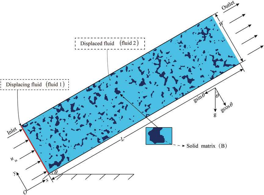
FIGURE 1. Schematic diagram of the initial state of the system.
Assuming that the two fluids are incompressible, the Boussinesq approximation can be adopted. The mixture density ρ and viscosity μ are assumed to be
where C ∈ [0, 1] is the mixture concentration, which represents the volume fraction of the displacing fluid; ρ2 is the density of the displaced fluid, βC is the solute expansion coefficient; μ2 is the viscosity of the displaced fluid,
The governing equations in this study include the continuity and Navier-Stokes equations, and the convection-diffusion equation for the concentration of the displacing fluid. The dimensionless governing equations can be written as follows:
The dimensionless parameters in Eqs 4–7 are defined as follows,
where u, v represent the velocity component in x and y directions, respectively; L* is the characteristic length, where L* is the width of the porous medium W; τ and p denote time and pressure; u* = ν2/W, t* = W2/ν2,
3 Lattice Boltzmann method
In this study, the lattice Boltzmann Method (LBM) is employed to solve the governing equations. Two distribution functions are used to simulate the velocity field and the concentration field, respectively.
The velocity field is described by the following evolution equation:
where fi(x, t) is the distribution function for particles at position x and time t with discrete velocity ci, δt is the time step, q is the number of discrete velocities, and Ωi(x, t) is the discrete collision operator, and Fi accounts for the body force F.
In LBM, the most widely used collision model is the single-relaxation-time or Bhatnagar-Gross-Krook (BGK) model. However, it has been shown that the BGK model has some shortcomings in pore-scale simulations, such as the unphysical viscosity-dependent permeability. On the other hand, the Multiple-Relaxtion-Time (MRT) model (Heyhat et al., 2020) can effectively solve the problem by introducing different relaxation times (Lallemand and Luo, 2000). Furthermore, the MRT model can also enhance the numerical stability, which is particularly useful for the present study where the viscosity ratio of the two fluids is large. Therefore, we will use the MRT model in the present study.
The collision operator in the MRT model can be expressed as:
where m and m(eq) are the moment and corresponding equilibria in moment space, respectively, and M is a q × q transformation matrix that maps the distribution functions to the moments’ space, m = M ⋅f, S = diag(s0, s1, … , sq−1) is a diagonal matrix of relaxation rates. In this work, we consider two-dimensional problems and use the two-dimensional nine-velocity (D2Q9) model where the discrete velocities are defined by
where c = δx/δt, with δx being lattice spacing. In the present work, c = 1. The transformation matrix M is defined as follows:
The corresponding discrete velocity moments of the distribution function are
where T represents the transpose operator, ρ is the fluid density, e and ɛ are related to the total energy and the energy square, jx and jy are components of the momentum, i.e., jx = ρux, jy = ρuy, qx and qy are the x and y components of the energy flux, pxx and pxy are related to the symmetric and traceless components of the stress tensor, respectively. For an incompressible fluid, the density of the fluid is approximately uniform and is denoted by ρ0, the density fluctuation is δρ, thus ρ = ρ0 + δρ. The corresponding equilibrium expressions of the moments are given by
and the relaxation matrix corresponding to the nine moments is
It should be noted that the fluid density and momentum are conserved during the collision process so that the relaxation rates corresponding to these moments, sρ and sj, can take arbitrary values. The other relaxation rates are given by se = sɛ = sν = 1/τν and sq = 8(2 − sν)/(8 − sν) (Pan et al., 2006), where τν is determined by the dimensionless kinematic viscosity ν(C),
The body force is defined as follows:
where
and
In the moment space, the body force
where
The fluid density and velocity can be obtained through the distribution function:
The concentration field is described by the lattice kinetic scheme (Inamuro, 2002), the evolution equation is given as:
where gi (x, t) accounts for the concentration C, and the discrete velocity set is the same as that used in the above MRT model for the velocity field; The equilibrium distribution function
where the weight coefficients are ω0 = 4/9, ω1−4 = 1/9, ω5−8 = 1/36,
The concentration is defined by the distribution function gi,
The concentration gradient in Eq. 26 can be obtained from the first-order moment of the non-equilibrium function at the given point,
and the final result is
Implementing boundary conditions is a fundamental problem in LBM (Lou et al., 2018). Since the fluid’s concentration and velocity are known at the inlet of the porous media, the non-equilibrium extrapolation scheme (Guo et al., 2002) is applied. The no-slip boundary condition is realized by the halfway bounce-back scheme (Ladd, 1994). It can be shown that if the relaxation rate τq is chosen as sq = 8(2 − sν)/(8 − sν) in the MRT model, the no-slip boundary condition can be realized accurately and spurious slip can be avoided (Pan et al., 2006). For the no-flux boundary condition, a similar bounce-back scheme is used (Wang et al., 2013). For the Neumann boundary condition at the outlet, the corresponding boundary condition scheme for the lattice Boltzmann method is given in Ref Lou et al. (2013).
The above LBM was previously proposed in Ref Liu et al. (2016) for solving Eqs 4–7. It has been validated that the above model has second-order accuracy in space, is insensitive to relaxation parameters, and is very stable at high Péclet number and large viscosity ratio compared with the lattice BGK model. As such, the model can accurately simulate the fluid flow and diffusion in porous media at high Péclet number and large viscosity ratio.
4 Results and discussion
We now use the LBM mentioned above to numerically simulate the miscible displacement in an inclined porous medium at the pore scale. The governing equations and boundary conditions for this problem are described in Sec. 2. The lattice size is 1,600 × 400. The robustness of our results has been tested successfully with longer and wider lattices (from 800 × 200 to 3,200 × 800), while keeping the same characteristic dimensionless numbers. The parameters are set as follows: Ra = 106, Sc = 80, and M = 54.6.
The temporal evolution of a dimensionless measure of the concentration of the displacing fluid “1” is plotted in Figure 2 to start the presentation of our results. The selected parameter values are typical of a situation in which a less viscous fluid displaces a more viscous fluid; in this case, one would expect the flow to be destabilized due to viscous contrasts and porous medium structure. As can be seen in Figure 2, at t = 0.125, the displacing fluid has just entered the porous medium and the fluid-fluid interface is clear. Then, the displacing fluid finds a path of least resistance, and the miscible displacement of fluid 2 by fluid 1 is accompanied by the development of instabilities, these manifest themselves via the formation of fingering structures. At t = 0.750 and 1.375, instabilities of the branching phenomena also arise from the structure of the porous medium. At the latter stages of the flow (t = 2.000), it can be seen that a distinct “dominant band” forms, and fingerings develop along this band in the porous medium.
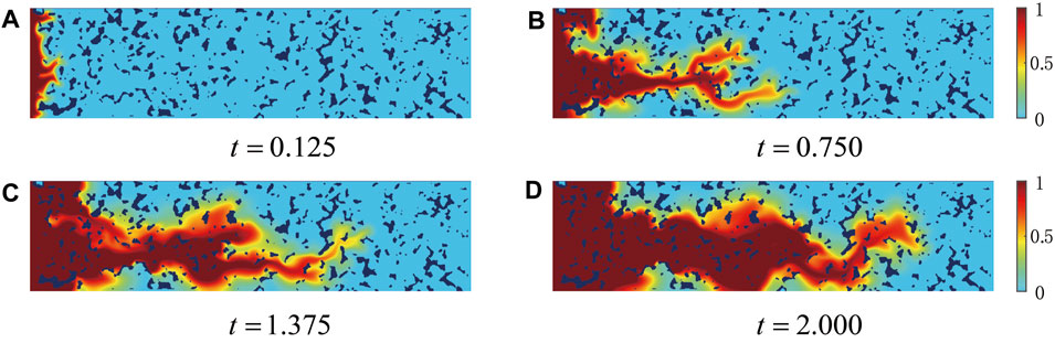
FIGURE 2. Evolution of concentration field without considering gravity field: (A) t = 0.125; (B) t = 0.750; (C) t = 1.375; and (D) t = 2.000.
4.1 Effects of inclination angle
The inclination angle significantly influences the development of viscous fingering and plays a crucial role in the miscible displacement process. We then focus on the effects of inclination angle on the displacement process, with the inclination angle ranging from θ = 0°–90°.
The miscible displacement considering the gravity is subsequently simulated. Figure 3 depicts the evolution of the concentration field for θ = 0°, 30°, 60°, and 90°, respectively. Figure 3A shows that the buoyancy effect appears early in the displacement process (t = 0.125). Compared to the cases of θ = 60° and 90°, the displacing fluid is impacted by the buoyancy and concentrated in the upper part of the porous medium the cases of θ = 0° and 30°. This effect is particularly noticeable at t = 0.750, 1.375 and 2.000. On the other hand, comparing Figures 2, 3, it can be observed that gravity has a substantial effect on miscible displacement behavior in porous media.
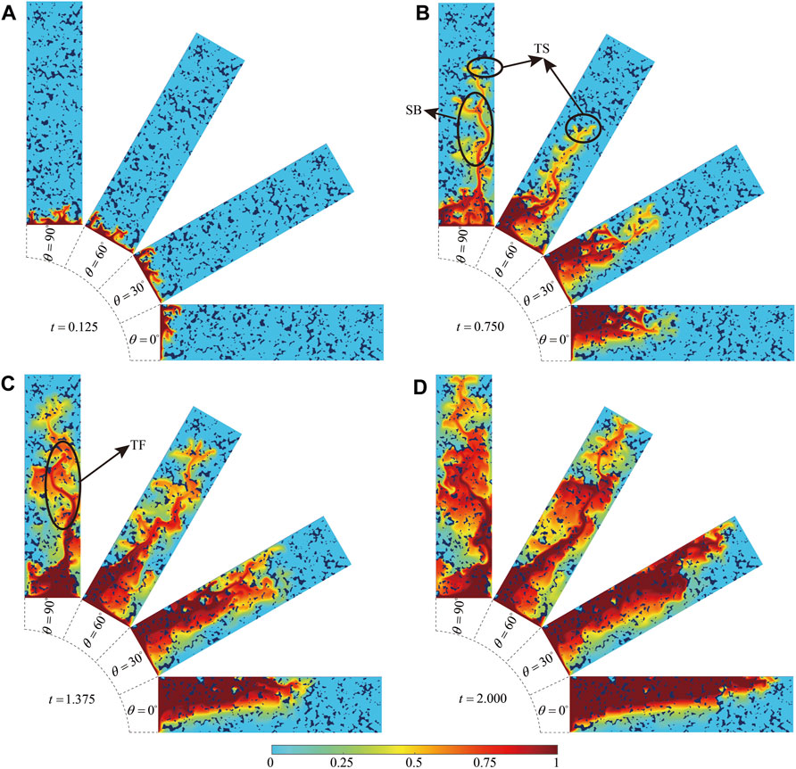
FIGURE 3. Evolution of concentration field at four different inclination angles: (A) t = 0.125; (B) t = 0.750; (C) t = 1.375; and (D) t = 2.000.
With the increase of time, the displacing fluid penetrates the displaced fluid in the form of fingerings. Figure 3B demonstrates “tip-splitting” (TS) and “side branching” (SB) phenomena in the front and middle of fingerings, respectively. At t = 1.375, weaker fingerings combine with stronger ones, resulting in the “tip-fusion” (TF) phenomenon (Meng and Guo, 2016). When t = 2.000, the displacement front is approaching the outlet, and it can be observed that the sweep range of the displacing fluid is larger at θ = 60° and 90° than at θ = 0° and 30°. Comparing 2 and 3, it can also be observed that displacement is faster when considering gravity. As shown in Figure 3, gradually increasing θ from 0° to 90° results in more rapid displacement.
To quantitatively analyze the effects of inclination angle on displacement, Figure 4 shows the displacement efficiency at different inclination angles. The displacement efficiency is defined as,
where V0.05 represents the volume occupied by the displacement fluid with C ≥ 0.05 in the porous medium at dimensionless time t, and V0 represents the total volume of the fluid.
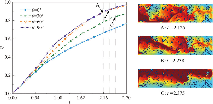
FIGURE 4. Evolution of displacement efficiency at different inclination angles, (A–C) represent the concentration fields when the displacing fluid front flows to the porous medium’s outlet at θ = 90°, 60°, and 30°, respectively.
Figure 4 shows the evolution of displacement efficiency at different inclination angles. It is clearly seen that the displacement efficiency progressively increases with time, and notably, a larger inclination angle corresponds to a higher displacement efficiency. However, when the inclination angle θ is equal to 60° and 90°, the difference in displacement efficiency is negligible. In Figure 4, points A (at t = 2.125), B (at t = 2.25), and C (at t = 2.375) represent the inflection points where the displacing fluid reaches the outlet at different angles; This is because the larger the θ, the greater the buoyancy force in the x direction and the faster the arrival at the outlet. As a result, increasing the inclination angle not only enhances the displacement efficiency but also shortens the time it takes for the displacing fluid to exit the outlet.
Figure 5 presents how displacement efficiency changes at times t = 0.750, 1.375, and 2.000 with varying inclination angles. The displacement efficiency can be divided into two zones as the inclination angle changes. In region I (θ = 0°–50°, displacement efficiency improves with the inclination angle. As the angle increases, the buoyancy force decreases in the y-direction and increases in the x-direction, making it easier for the displacing fluid to move forward and boosting efficiency. In region II (θ = 50°–90°, increasing the inclination angle does not impact the displacement efficiency, and the displacement efficiency tends to remain steady.
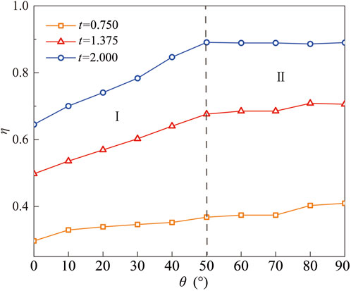
FIGURE 5. Displacement efficiencies at different inclination angles at t = 0.750, 1.375, and 2.000.
4.2 Effects of viscosity ratio
This section investigates the effects of the viscosity ratio (M) on the displacement process, with the inclination angle fixed at θ = 60° and other parameters set as follows: Ra = 106, Sc = 80. Initially, the cases of M ≥ 1 are studied. Figure 6 presents the concentration distribution evolution for seven different viscosity ratios, with subfigures (a)-(g) corresponding to M = 1.0, 2.72, 7.39, 20.09, 54.6, 79.84, and 100.0, respectively. It is observed that with the increase in the viscosity ratio, the effect of viscous fingering becomes more noticeable. Beyond a certain point, increasing the viscosity ratio has a minor impact on the morphology of fingering (for example: M = 54.6, M = 79.84, and M = 100.0). As the viscosity ratio increases, so does the differential in viscosity between the displacing and displaced fluids, resulting in more dramatic finger stretching in the displacement direction. Simultaneously, the force component in the x-direction on the displacing fluid increases, enhancing the buoyancy effect. This permits the displacing fluid to reach the porous medium’s outlet more quickly, resulting in longer and finer fingering forms.
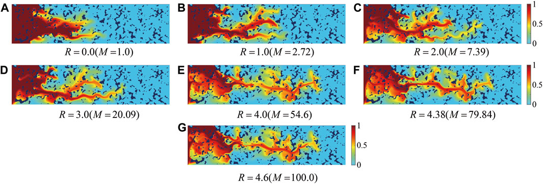
FIGURE 6. Concentration fields at different viscosity ratios at t = 1.125: (A) M = 1.0; (B) M = 2.72; (C) M = 7.39; (D) M = 20.09; (E) M = 54.6; (F) M = 79.84; and (G) M = 100.0.
The subsequent analysis focuses on displacement efficiency for certain viscosity ratios. Figure 7A shows that when the viscosity ratio increases, the displacement rate accelerates. When M = 1.0, there is no viscosity difference between the two fluids. In this case, the displacing fluid flows stably in the direction of displacement, with minimal influence from buoyancy, and is significantly affected by the permeability of the porous medium, resulting in the slowest displacement rate and the longest time for the leading edge to reach the outlet. Conversely, at M = 100.0, the flow characteristics display considerable fingering phenomena and are significantly influenced by buoyancy, resulting in the fastest displacement and the shortest time for the leading edge to reach the outlet. This indicates that an increase in viscosity ratio significantly enhances the rate of growth in displacement efficiency. From Figure 7B, it is observed that at t = 2.5, the displacement efficiency noticeably increases with the viscosity ratio. However, when M ≥ 54.6, the change in displacement efficiency becomes less pronounced, stabilizing at η = 0.97. This implies the existence of a critical viscosity ratio Mcr, beyond which the influence on the fluid flow pattern and displacement efficiency becomes less significant. In the cases discussed in this study, the critical viscosity ratio is Mcr = 54.6.
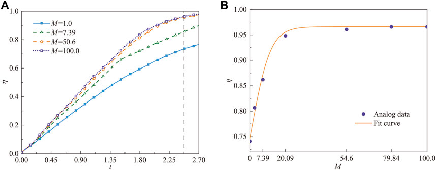
FIGURE 7. (A) Evolution of displacement efficiency at different viscosity ratios, and (B) the fitting curve of the displacement efficiency at t = 2.5.
Figure 8 illustrates the evolution of the average concentration in the x-direction at different viscosity ratios. The average concentration in the x-direction is defined as follows:
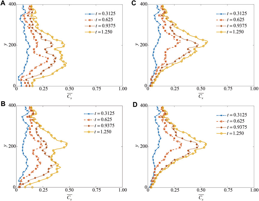
FIGURE 8. Variation of the average concentration in the x-direction at different viscosity ratios: (A) M = 1.0; (B) M = 20.09; (C) M = 54.6; and (D) M = 100.0.
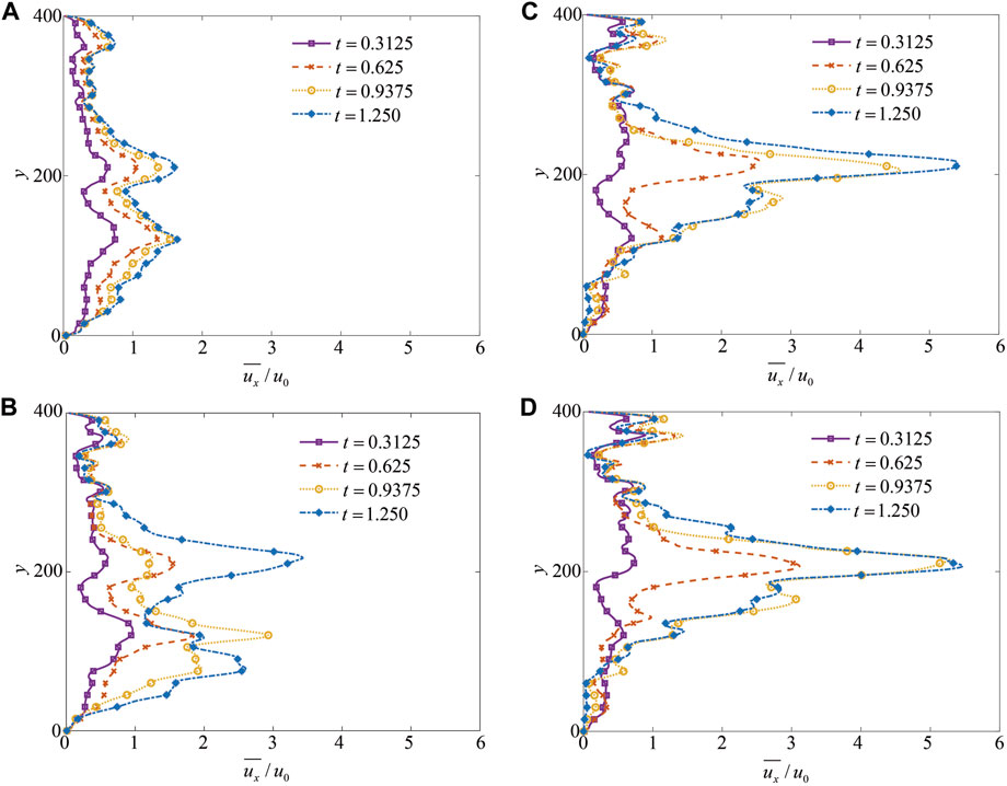
FIGURE 9. Variation of the mean velocity in the x-direction at different viscosity ratios: (A) M = 1.0; (B) M = 20.09; (C) M = 54.6; and (D) M = 100.0.
The discussion is also extended to the cases where the viscosity ratio M ≤ 1.0, with four distinct viscosity ratios selected and parameter settings consistent with the previous discussion. As shown in Figure 10, it is observed that when M < 1.0, there are no significant fingering instabilities. Furthermore, as the viscosity ratio decreases, the displacement rate slows, and the fingering instability eventually fades, resulting in a “plug flow” state. This is because when M < 1.0, the viscosity of the displacing fluid is much higher than that of the displaced fluid, leading to increased resistance to displacement, and reduced instability phenomenon.
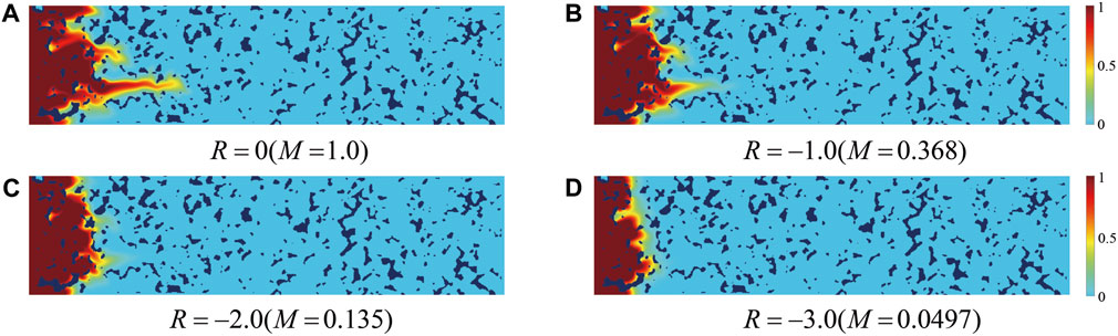
FIGURE 10. Concentration fields at t = 0.50: (A) M = 1.0; (B) M = 0.368; (C) M = 0.135; and (D) M = 0.0497.
4.3 Effects of porous medium structure
The above conclusions are based on the porous medium structure shown in Figure 1. To verify the generality of the preceding conclusions, we then select two different porous medium structures with different porosities for numerical simulation of miscible displacement. Choose the same porous medium for CT scanning, collect grayscale images of other parts, and use binary image processing to get two porous media with porosity of 0.763 and 0.805, as shown in Figure 11. It can be observed from Figures 1, 11 that the heterogeneity of the porous media in this study is not significant.

FIGURE 11. Porous media with porosities of (A) 0.763 and (B) 0.805, respectively.
Another fundamental property of porous media is permeability, which describes the difficulty of fluid flow in a porous medium and can be expressed as a second-order tensor, K,

TABLE 1. Porosity and permeability of porous media.
Figure 12 shows the concentration fields at different inclination angles at t = 2.0. The parameters are consistent with Sec. 4.1. It can be seen that although the structure of the porous medium has altered, the shape of the displacement fluid is similar to that described in Sec. 4.1. When the inclination angle is small (θ = 0° and 30°), the component force in the y-direction is larger, causing the displacing fluid to float upwards and flow along the upper wall. When the inclination angle is large (θ = 60° and 90°), the force in the x-direction increases, leading to rapid displacement along the x-direction.
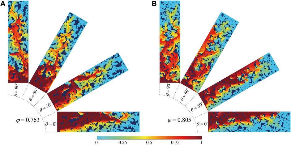
FIGURE 12. Concentration fields at different inclination angles at t = 2.000: (A) φ = 0.763; (B) φ = 0.805.
Figure 13 shows that under two different porous media structures, the change in displacement efficiency with increasing inclination angle can also be divided into two regions, namely, Region I and Region II. In Region I, as the inclination angle increases, the displacement efficiency increases; In Region II, the displacement efficiency remains relatively stable. This conclusion is consistent with the previous one. This indicates that the conclusions of the previous study are still applicable in porous media structures with low heterogeneity and anisotropy, indicating that the research findings are universal.
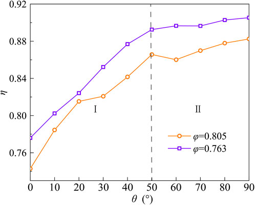
FIGURE 13. Displacement efficiencies at different inclination angles at t = 2.000.
5 Conclusion
In this paper, we have studied the displacement process of miscible fluids in porous media at the pore scale while taking gravity into account by using a LBM. The study investigated the temporal distribution of fluid concentration fields in porous media under gravitational influences. Gravity’s impact on the displacement process was explored by comparing it to cases with no gravitational influence. Additionally, the impact of inclination angle (θ) and viscosity ratio (M) on interface stability and displacement efficiency was investigated. The conclusions are as follows.
1) As the inclination angle increases, the viscous fingering instability in porous media becomes more apparent. The displacement efficiency is divided into two regions when the inclination angle increases. One region is when the inclination angle ranges from 0° to 50°. At this time, as the inclination angle increases, so does the displacement efficiency. In the other region, the inclination angle ranges from 50° to 90°, and as the inclination angle increases, the displacement efficiency remains relatively stable.
2) When the inclination angle is fixed (selected as θ = 60° in this study), an increase in the viscosity ratio (M) results in more pronounced fingering phenomena. The larger the viscosity ratio, the faster the viscous fingerings, gradually improving the displacement efficiency. There exists a critical viscosity ratio (Mcr) that stabilizes the displacement efficiency near the critical point. When (M < 1.0), the resistance to displacement increases, resulting in a “plug flow” state.
3) For porous media with less visible heterogeneity and anisotropy, the trend of displacement efficiency changing with inclination angle is consistent, indicating the universality of the above conclusions.
Data availability statement
The raw data supporting the conclusions of this article will be made available by the authors, without undue reservation.
Author contributions
GL: Methodology, Writing–original draft. AX: Conceptualization, Writing–original draft. YW: Data curation, Writing–review and editing. QL: Methodology, Writing–review and editing.
Funding
The author(s) declare financial support was received for the research, authorship, and/or publication of this article. This work was supported by the National Natural Science Foundation of China (Grant Nos. 51806142, 51976128, and 52376068).
Conflict of interest
The authors declare that the research was conducted in the absence of any commercial or financial relationships that could be construed as a potential conflict of interest.
Publisher’s note
All claims expressed in this article are solely those of the authors and do not necessarily represent those of their affiliated organizations, or those of the publisher, the editors and the reviewers. Any product that may be evaluated in this article, or claim that may be made by its manufacturer, is not guaranteed or endorsed by the publisher.
References
Bacri, J.-C., Salin, D., and Wouméni, R. (1991). Three-dimensional miscible viscous fingering in porous media. Phys. Rev. Lett. 67, 2005–2008. doi:10.1103/PhysRevLett.67.2005
Bashir, A., Sharifi Haddad, A., and Rafati, R. (2022). A review of fluid displacement mechanisms in surfactant-based chemical enhanced oil recovery processes: analyses of key influencing factors. Petroleum Sci. 19, 1211–1235. doi:10.1016/j.petsci.2021.11.021
De Wit, A., and Homsy, G. M. (1997). Viscous fingering in periodically heterogeneous porous media. I. Formulation and linear instability. J. Chem. Phys. 107, 9609–9618. doi:10.1063/1.475258
Elgahawy, Y., and Azaiez, J. (2021). Dynamics of buoyancy driven miscible iso-viscous flows in heterogeneous layered porous media. Phys. Fluids 33, 074104. doi:10.1063/5.0054659
Guo, Z., Zheng, C., and Shi, B. (2002). Discrete lattice effects on the forcing term in the lattice Boltzmann method. Phys. Rev. E 65, 046308. doi:10.1103/PhysRevE.65.046308
Heyhat, M. M., Mousavi, S., and Siavashi, M. (2020). Battery thermal management with thermal energy storage composites of PCM, metal foam, fin and nanoparticle. J. Energy Storage 28, 101235. doi:10.1016/j.est.2020.101235
Homsy, G. M. (1987). Viscous fingering in porous media. Annu. Rev. Fluid Mech. 19, 271–311. doi:10.1146/annurev.fl.19.010187.001415
Huo, Y., Yin, M., and Rao, Z. (2022). Heat transfer enhanced by angle-optimized fan-shaped porous medium in phase change thermal energy storage system at pore scale. Int. J. Therm. Sci. 172, 107363. doi:10.1016/j.ijthermalsci.2021.107363
Inamuro, T. (2002). A lattice kinetic scheme for incompressible viscous flows with heat transfer. Phil. Trans. R. Soc. Lond. A 360, 477–484. doi:10.1098/rsta.2001.0942
Javed, M. S., Ma, T., Jurasz, J., and Amin, M. Y. (2020). Solar and wind power generation systems with pumped hydro storage: review and future perspectives. Renew. Energy 148, 176–192. doi:10.1016/j.renene.2019.11.157
Jia, B., Tsau, J.-S., and Barati, R. (2019). A review of the current progress of CO2 injection EOR and carbon storage in shale oil reservoirs. Fuel 236, 404–427. doi:10.1016/j.fuel.2018.08.103
Jiao, C., and Hötzl, H. (2004). An experimental study of miscible displacements in porous media with variation of fluid density and viscosity. Transp 54, 125–144. doi:10.1023/A:1026383019300
Jiao, C., and Maxworthy, T. (2008). An experimental study of miscible displacement with gravity-override and viscosity-contrast in a Hele Shaw cell. Exp. Fluids 44, 781–794. doi:10.1007/S00348-007-0434-8
Koohi-Fayegh, S., and Rosen, M. (2020). A review of energy storage types, applications and recent developments. J. Energy Storage 27, 101047. doi:10.1016/j.est.2019.101047
Kuang, J., Maxworthy, T., and Petitjeans, P. (2003). Miscible displacements between silicone oils in capillary tubes. Eur. J. Mech. B/Fluids 22, 271–277. doi:10.1016/S0997-7546(03)00035-9
Lackey, G., Freeman, G. M., Buscheck, T. A., Haeri, F., White, J. A., Huerta, N., et al. (2023). Characterizing hydrogen storage potential in U.S. underground gas storage facilities. Geophys. Res. Lett. 50, e2022GL101420. doi:10.1029/2022GL101420
Ladd, A. J. C. (1994). Numerical simulations of particulate suspensions via a discretized Boltzmann equation. Part 1. Theoretical foundation. J. Fluid Mech. 271, 285–C309. doi:10.1017/S0022112094001771
Lallemand, P., and Luo, L. S. (2000). Theory of the lattice Boltzmann method: dispersion, dissipation, isotropy, galilean invariance, and stability. Phys. Rev. E 61, 6546–6562. doi:10.1103/physreve.61.6546
Lankof, L., and Tarkowski, R. (2020). Assessment of the potential for underground hydrogen storage in bedded salt formation. Int. J. Hydrogen Energy 45, 19479–19492. doi:10.1016/j.ijhydene.2020.05.024
Lei, T., and Luo, K. H. (2019). Pore-scale study of dissolution-driven density instability with reaction A + B → C in porous media. Phys. Rev. Fluids 4, 063907. doi:10.1103/PhysRevFluids.4.063907
Lei, T., and Luo, K. H. (2021). Pore-scale simulation of miscible viscous fingering with dissolution reaction in porous media. Phys. Fluids 33, 034134. doi:10.1063/5.0045051
Liu, C., Cheng, Q., Li, B., Liu, X., and Rao, Z. (2023a). Recent advances of sugar alcohols phase change materials for thermal energy storage. Renew. Sust. Energy Rev. 188, 113805. doi:10.1016/j.rser.2023.113805
Liu, G., and Guo, Z. (2015). Pore-scale study of the non-linear mixing of fluids with viscous fingering in anisotropic porous media. Comput. Phys. Commun. 17, 1019–C1036. doi:10.4208/cicp.2014.m347
Liu, G., Guo, Z., and Shi, B. (2016). A coupled lattice Boltzmann model for fluid flow and diffusion in a porous medium. Acta Phys. Sin. 65, 014702. doi:10.7498/aps.65.014702
Liu, G., Wang, Y., Zhang, C., and Lou, Q. (2023b). Numerical simulations of miscible displacement in an inclined channel by lattice Boltzmann method. Phys. Fluids 35, 032106. doi:10.1063/5.0135734
Liu, H., Yang, C., Liu, J., Hou, Z., Yachen Xie, X. S., and Shi, X. (2023c). An overview of underground energy storage in porous media and development in China. J. Nat. Gas. Sci. Eng. 117, 205079. doi:10.1016/j.jgsce.2023.205079
Lou, Q., Guo, Z., and Shi, B. (2013). Evaluation of outflow boundary conditions for two-phase lattice Boltzmann equation. Phys. Rev. E 87, 063301. doi:10.1103/physreve.87.063301
Lou, Q., Yang, m., and Xu, H. (2018). Wetting boundary condition in an improved lattice Boltzmann method for nonideal gases. Commun. Comput. Phys. 23, 1116–1130. doi:10.4208/cicp.OA-2016-0211
Meng, X., and Guo, Z. (2016). Localized lattice Boltzmann equation model for simulating miscible viscous displacement in porous media. Int. J. Heat. Mass Transf. 100, 767–778. doi:10.1016/j.ijheatmasstransfer.2016.04.095
Naghavi Sanjani, M. S., Silakhori, M., Ang, B. C., Simon Cornelis Metselaar, H., Mousavi Gazafroudi, S. M., and Noorollahi, Y. (2023). Experimental investigation on solar water heater integrated with thermal battery using phase change material and porous media. SSRN Electron. J. 15, 6439. doi:10.3390/su15086439
Norouzi, M., and Shoghi, M. R. (2014). A numerical study on miscible viscous fingering instability in anisotropic porous media. Phys. Fluids 26, 084102. doi:10.1063/1.4891228
Pan, C., Luo, L.-S., and Miller, C. T. (2006). An evaluation of lattice Boltzmann schemes for porous medium flow simulation. Comput. Fluids 35, 898–909. doi:10.1016/j.compfluid.2005.03.008
Rehman, S., Al-Hadhrami, L. M., and Alam, M. M. (2015). Pumped hydro energy storage system: a technological review. Renew. Sust. Energy Rev. 44, 586–598. doi:10.1016/j.rser.2014.12.040
Saffman, P. G., and Taylor, G. I. (1958). The penetration of a fluid into a porous medium or Hele-Shaw cell containing a more viscous liquid. Proc. R. Soc. Lond. A 245, 312–329. doi:10.1098/rspa.1958.0085
Strobel, G., Hagemann, B., Huppertz, T. M., and Ganzer, L. (2020). Underground bio-methanation: concept and potential. Renew. Sust. Energy Rev. 123, 109747. doi:10.1016/j.rser.2020.109747
Tan, C. T., and Homsy, G. M. (1986). Stability of miscible displacements in porous media: rectilinear flow. Phys. Fluids 29, 3549–3556. doi:10.1063/1.865832
Tosco, T., Petrangeli Papini, M., Cruz Viggi, C., and Sethi, R. (2014). Nanoscale zerovalent iron particles for groundwater remediation: a review. J. Clean. Prod. 77, 10–21. doi:10.1016/j.jclepro.2013.12.026
Wang, J., Wang, D., Lallemand, P., and Luo, L.-S. (2013). Lattice Boltzmann simulations of thermal convective flows in two dimensions. Comput. Math. Appl. 65, 262–286. doi:10.1016/j.camwa.2012.07.001
Yang, Y., Shen, Z., Wu, W., Zhang, H., Ren, Y., and Yang, Q. (2022). Preparation of a novel diatomite-based PCM gypsum board for temperature-humidity control of buildings. Build. Environ. 226, 109732. doi:10.1016/j.buildenv.2022.109732
Yang, Y., Wu, W., Fu, S., and Zhang, H. (2020). Study of a novel ceramsite-based shape-stabilized composite phase change material (PCM) for energy conservation in buildings. Constr. Build. Mat. 246, 118479. doi:10.1016/j.conbuildmat.2020.118479
Zeeshan Mohiuddin, M. H., Stokes, Y., and Haghighi, M. (2013). Pore level simulation of miscible injection with gravity domination. Energy Procedia 37, 6885–6900. doi:10.1016/j.egypro.2013.06.621
Zhang, Y., Yang, L., and Huang, W. (2023). Study on hydrogen flow and heat transfer in underground salt cavern hydrogen storage. J. Phys. Conf. Ser. 2599, 012017. doi:10.1088/1742-6596/2599/1/012017
Zimmerman, W. B., and Homsy, G. M. (1992). Viscous fingering in miscible displacements: unification of effects of viscosity contrast, anisotropic dispersion, and velocity dependence of dispersion on nonlinear finger propagation. Phys. Fluids A Fluid Dyn. 4, 2348–2359. doi:10.1063/1.858476
Keywords: miscible displacement, viscous fingering, inclined porous media, displacement efficiency, lattice Boltzmann method
Citation: Liu G, Xu A, Wang Y and Lou Q (2024) Pore-scale simulation of miscible displacement in an inclined porous medium. Front. Energy Res. 12:1366187. doi: 10.3389/fenrg.2024.1366187
Received: 05 January 2024; Accepted: 22 January 2024;
Published: 08 February 2024.
Edited by:
Haotian Liu, University of California, Los Angeles, United StatesReviewed by:
Xuejin Zhou, Huaqiao University, ChinaLei Wang, China University of Geosciences Wuhan, China
Copyright © 2024 Liu, Xu, Wang and Lou. This is an open-access article distributed under the terms of the Creative Commons Attribution License (CC BY). The use, distribution or reproduction in other forums is permitted, provided the original author(s) and the copyright owner(s) are credited and that the original publication in this journal is cited, in accordance with accepted academic practice. No use, distribution or reproduction is permitted which does not comply with these terms.
*Correspondence: Gaojie Liu, bGl1Z2pAdXNzdC5lZHUuY24=