 Luyao Xie
 Yu Zhang
 Youbing Zhang
 Yi Chen2
- 1College of Information Engineering, Zhejiang University of Technology, Hangzhou, China
- 2Zhijiang College of Zhejiang University of Technology, Shaoxin, China
- 3HRV ELECTRIC, Hangzhou, China
In a microgrid system where multiple virtual synchronous generators (VSGs) are interconnected through high impedance cables, the total output negative sequence and harmonic current of multiple VSGs cannot be coordinated based on the capacity of each power conversion system (PCS). In addition, there is significant distortion in the voltage at the point of common coupling (PCC). Because the impedance amplitude and impedance angle of the cable change with the harmonic frequency, the resistive virtual impedance reshaping method and fixed impedance angle virtual impedance reshaping method used in the current research cannot solve the harmonic current distribution problem. To solve the above problems, a multi-frequency points VSG impedance reshaping control strategy is proposed in this paper, which can adjust the resistive and inductive output impedance of each harmonic frequency independently. The strategy is based on the harmonic separation algorithm of LPF with Feedforward Compensation (FCLPF) and the voltage controller of Vector Proportional Integral (VPI) in fundamental dq rotation coordinate system, which effectively improve the flexibility and accuracy of harmonic impedance reshaping. Among them, FCLPF harmonic separation algorithm has the characteristics of target frequency bandpass and non-target frequency notch, and can eliminate the coupling interference of each harmonic virtual impedance when accumulating virtual impedance voltage references at various frequency points. The closed-loop transfer function of the multi-parallel VPI voltage controller has the characteristics of unit gain and zero phase shift at each harmonic frequency point, which means the static response error of virtual impedance voltage command can be almost completely eliminated. Under the proposed control strategy, the fundamental positive power can be allocated according to the droop coefficient, the fundamental negative current and harmonic current can be allocated according to the sum of the reshaped virtual impedance and the actual line impedance. Reshaping virtual impedance at each harmonic frequency to negative value can also compensate the harmonic voltage drop on the high impedance cable and improve the voltage quality at the PCC.
1 Introduction
Among various grid-forming controls, VSG control enables PCS to have similar P-F and Q-V characteristics as synchronous generators, providing inertia (Chen et al., 2023) and damping (Li et al., 2023a) for the power grid, which is beneficial for improving the stability of the power grid (Li et al., 2023b; Ji et al., 2023). Nowadays, the problem of coordinated allocation of fundamental positive sequence current in multi parallel systems under VSG control can be effectively solved through methods such as droop control (Xu et al., 2019; Rasool et al., 2023a). However, when it comes to the coordinated control of nonlinear and negative sequence currents, there are still some problems such as low current distribution accuracy and excessive voltage distortion (Moussa et al., 2018; Alwaz et al., 2019).
At present, virtual impedance control is used to solve the problem of harmonic current sharing and PCC voltage quality optimization of multi-PCS parallel systems under nonlinear and negative sequence load conditions. In terms of improving harmonic current sharing by virtual impedance reshaping, references (Das et al., 2021; Deng et al., 2022) realized the fixed resistance virtual impedance control based on the traditional droop control, and realized the harmonic current sharing in the whole frequency band. The harmonic current feedforward compensation control and impedance remodeling factor are introduced to adaptively reshape the harmonic impedance amplitude of the inverter with a fixed impedance angle, so as to realize the coordinated distribution of harmonic current and the optimization of PCC voltage quality (Wang et al., 2021; Wang et al., 2022). Without communication or additional sensors, (Vijay et al., 2021a; Vijay et al., 2021b), proposed a droop control strategy to reshape the fundamental positive and fundamental negative sequence virtual impedance, and realized the coordinated equalization of fundamental positive and fundamental negative sequence power. In general, part of the literature above assumes that the impedance of PCS feed line is resistive, and the problem of harmonics coordination can be solved by resistive virtual impedance. Or assume that the PCS feed line impedance is small, so the harmonic current coordination problem can be solved by the dominant virtual impedance. The above literature also discusses how to minimize the virtual impedance to reduce the voltage distortion at PCC while ensuring the accuracy of harmonic current distribution. However, the above-mentioned resistive virtual impedance or fixed impedance angle virtual impedance reshaping method cannot solve the problem of harmonic current distribution when the PCS feeder impedance is large or the feeder impedance angle is inconsistent. In order to solve the above problems, it is necessary to explore a virtual impedance reshaping method that can arbitrarily adjust the virtual resistance and virtual inductance at various harmonic frequency points.
At present, the implementation process of arbitrary impedance shaping strategy for multi-harmonic frequency points usually needs to construct the harmonic virtual impedance voltage drop through the harmonic current separation algorithm, and then use the harmonic voltage controller to accurately track the instructions. In terms of harmonic current separation algorithm, Low Pass Filter (LPF) is adopted in (Dong et al., 2018) to separate each harmonic component of voltage or current. Moving Average Filter (MAF) is adopted in (Qi et al., 2020) to separate the positive and negative sequence components in voltage or current. A LPF harmonic separation algorithm with feedforward of fundamental positive component is adopted in (Göthner et al., 2019) to improve the harmonic separation accuracy. Reference (Huang et al., 2020; Nguyen et al., 2022) successfully constructed the harmonic voltage drop of inductive virtual impedance using the bandpass characteristics of Second Order Generalized Integrator (SOGI) or Third Order Generalized Integrator (TOGI). However, SOGI or TOGI are high-order controllers and can only realize the integration operation at a single frequency point, which is too complicated in constructing the virtual impedance voltage drop command at multi-frequency points. In general, the harmonic separation algorithms in the above literature have the problem of coupling interference of voltage commands at each frequency point when constructing the harmonic virtual impedance voltage drop, which results in the decrease of the virtual impedance control accuracy. In terms of harmonic voltage control, PI controller in multi-dq coordinate system is adopted in (Dong et al., 2018) to realize the control of each harmonic voltage, but there are too many control loops and the calculation is complicated. PI and QPR controllers in dq coordinate system are adopted in (Göthner et al., 2019), which reduce the number of voltage controllers and simplify the calculation. Repetitive controller can also realize the control of multi-harmonic components (Xu et al., 2023). However, it introduces the delay link, which leads to the degradation of the dynamic performance of the system. Reference (Gong et al., 2021) demonstrates that the Bode plot of the closed-loop transfer function of the VPI controller is smooth around the target frequency point, and the control error is small compared to the QPR controller in the presence of frequency deviation. Overall, although all of the above voltage controllers are capable of controlling the harmonic voltage components, there are differences in the accuracy and dynamic performance, which may lead to further amplification of errors in virtual impedance control.
In order to solve the problem of harmonic current sharing and voltage quality optimization of microgrid system with multiple VSGs interconnected by high impedance cables, the main contributions of this paper are as follows:
A multi-frequency points VSG impedance reshaping control strategy combining the advantages of FCLPF harmonic separation algorithm and multi-parallel VPI controller is proposed in this paper. Among them, the harmonic separation algorithm based on FCLPF has the characteristics of bandpass filter at the target frequency, and the characteristics of notch at the non-target frequency. Based on each harmonic current extracted by FCLPF, the inductive and resistive impedance voltage drop of each harmonic frequency point can be independently constructed, and the coupling problem between the impedance voltage drop instructions of each frequency point can be solved. The voltage closed-loop transfer function of multi-parallel VPI voltage controller has unity gain and zero phase shift at each target frequency point, and the gain on both sides of each target frequency point decreases rapidly. It also has the decoupling characteristic of dq axis, which solves the problem that the traditional QPR voltage controller has low control accuracy at each harmonic frequency point. Based on the above characteristics, the multi-frequency VSG impedance reshaping control strategy proposed in this paper has advantages in the flexibility and accuracy of harmonic impedance reshaping, and can improve the precision of harmonic current coordination distribution and the voltage quality of PCC.
The structure of this article is arranged as follows. Firstly, the system structure of multi-VSG current coordinated distribution and voltage optimization control is introduced. Secondly, each part of multi-frequency VSG impedance reshaping control strategy is described and analyzed in detail. Then, based on multi-frequency VSG impedance reshaping control, the coordinated distribution of the total output current of multiple VSGs and the optimization of PCC voltage quality are discussed. Finally, a model of dual VSG parallel system based on Hardware In the Loop (HIL) simulation platform is built to verify the correctness and effectiveness of the control strategy proposed in this paper.
2 The system structure of multi-VSG current coordinated distribution and voltage optimization control
Under distorted load conditions, the system structure of multi-VSG current coordinated distribution and voltage optimization control is illustrated in Figure 1. In Figure 1,
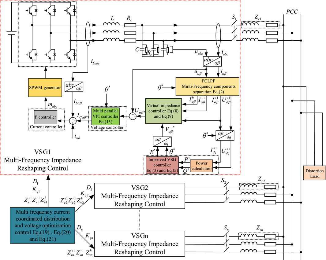
Figure 1. The system structure of multi-VSG current coordinated distribution and voltage optimization control.
The control structure in Figure 1 can be divided into two layers: the multi-frequency points virtual impedance reshaping control at the bottom layer and the coordinated current allocation and voltage optimization control at the top layer. The core of this article is multi-frequency points virtual impedance reshaping control. Firstly, FCLPF is used to extract the various frequency components of the load current. Then, virtual impedance voltage at multi-frequency points is constructed through a virtual impedance loop, and the fundamental positive voltage instruction
3 VSG control strategy based on multi frequency impedance reshaping
3.1 Harmonic separation strategy based on FCLPF
As shown in Figure 2, a harmonic separation strategy based on low-pass filtering and feedforward compensation in multi-synchronous rotating dq coordinate systems is adopted in this paper. The positive sequence component, negative sequence component and harmonic component are separated and multiplied by the independently adjustable virtual impedance to construct the voltage command of the virtual impedance at multiple frequencies.
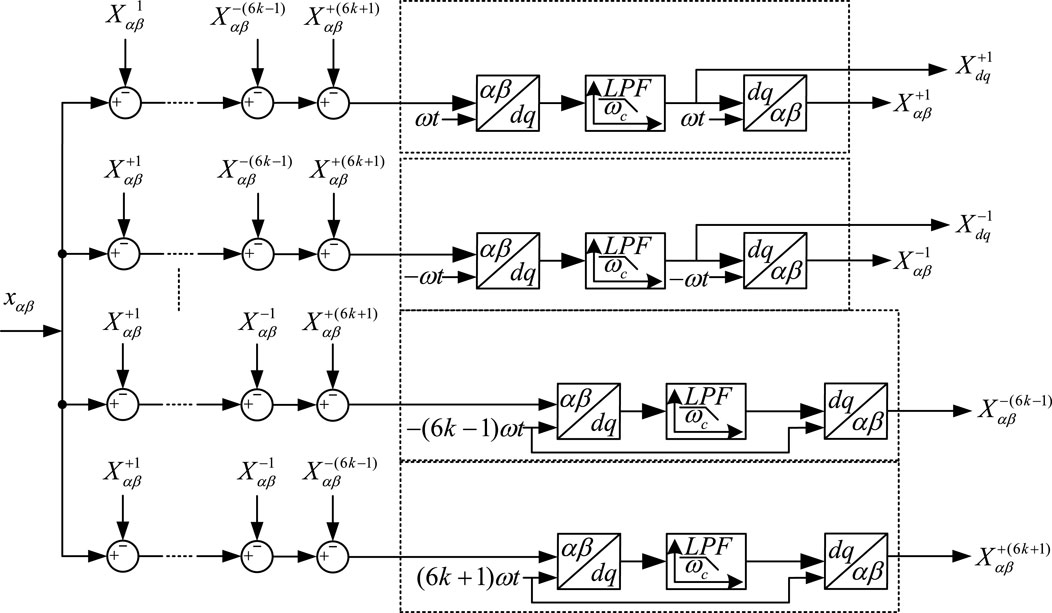
Figure 2. Multi-frequency points components separation strategy based on feedforward compensation and low pass filtering in multi synchronous dq reference frame.
In Figure 2,
Assuming that k is taken to 2, the relationship between the extracted harmonic static component and the original quantity in αβ coordinate system can be written as Eq. 1. According to the frequency shift theorem of Laplace transform, the closed-loop transfer function of the extracted static component and the original quantity in fundamental dq coordinate system can be obtained as Eq. 2, and the Bode plot is shown in Figure 3. Analyzing Figure 3, taking the fundamental positive sequence component extraction transfer function as an example, it has unit gain and zero phase offset at the target frequency of 0Hz, and the farther away from the target frequency, the smaller the gain. Its band-pass filtering characteristics can accurately extract the static component at the target frequency. At the non-target frequencies of −100Hz, ±300 Hz and ±600Hz, it has notch characteristics. When the virtual impedance voltage command is accumulated, it can well shield the influence of mutual coupling and has better extraction performance.

Figure 3. Bode diagram of harmonic separation transfer functions in fundamental positive sequence dq coordinate reference frame.
Where
Where
3.2 Multi-frequency virtual impedance voltage command generation
3.2.1 Fundamental positive voltage command generation
The improved VSG control loop is mainly divided into active power frequency regulator and reactive power voltage regulator. By referring to the rotor motion equation of the synchronous generator, the active power frequency regulator (Qu et al., 2021) can be written as shown in in Eq. 3, and the time constant of power loop is shown in Eq. 4:
Where
The traditional reactive power voltage regulator models the PCS output port as a constant-factor Q-V droop characteristic, which cannot realize the accurate distribution of reactive power among multiple PCSs because of not considering the impedance voltage drop of the feed line (Rasool et al., 2023b). In this paper, the static compensation term of the voltage drop on the virtual impedance and the actual impedance is added to make the Q-V droop characteristic at the PCC point a fixed coefficient, so as to achieve accurate reactive power distribution. The fundamental positive sequence virtual impedance value should follow the following principles: Firstly, the sum of the virtual impedance and the feed line impedance should be inductive to improve the decoupling performance of active power and reactive power in droop control; Secondly, the sum of the virtual impedance and the feed line impedance of each parallel branch is set according to the ratio of the reciprocal of PCS capacity, so as to compensate the inconsistency of line impedance and improve the distribution performance of fundamental power. The improved reactive power voltage regulator equation is shown in Eq. 5.
Where
According to Eqs 3, 5, the control block diagram of the improved VSG control strategy can be drawn, as shown in Figure 4.
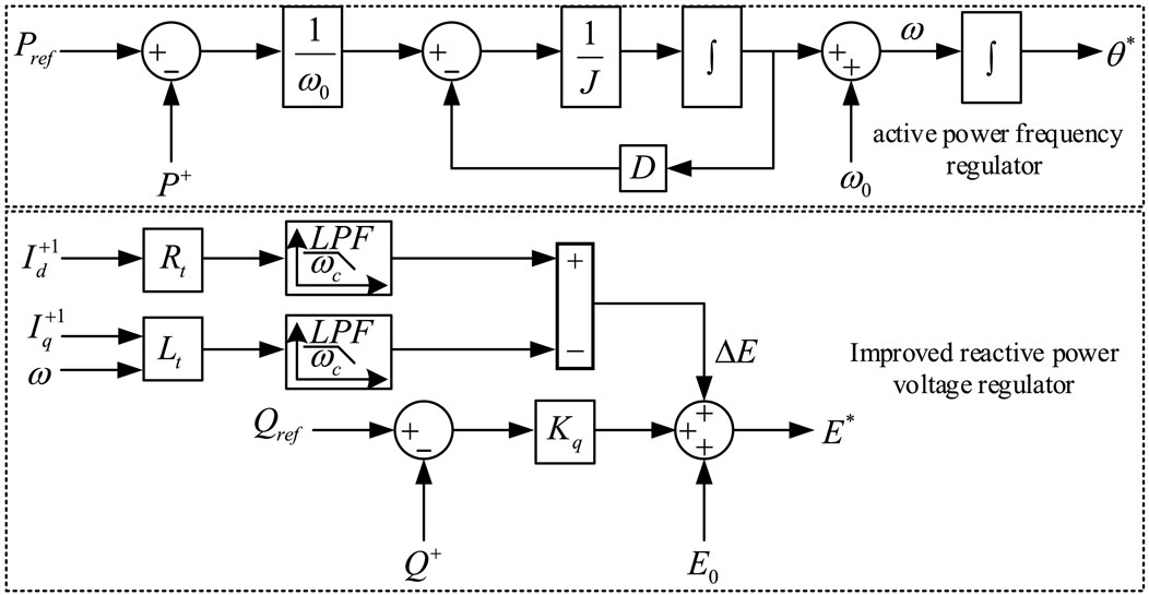
Figure 4. Control block diagram of improved VSG control strategy.
The fundamental voltage reference
The voltage command of virtual impedance at fundamental positive frequency is shown in Eq. 7.
Where
The final fundamental positive voltage command can be obtained by adding Eqs 6, 7.
The positive sequence virtual impedance introduced in this section compensates the influence of impedance inconsistency of each parallel PCS and improves the distribution performance of fundamental positive power. By constructing the sum of the line impedance and virtual impedance as inductive, the decoupling characteristics of active and reactive power can be enhanced. In addition, the introduced voltage compensation can improve the distribution accuracy of reactive power.
3.2.2 Voltage command generation of negative and harmonic virtual impedance
The voltage command of the negative and harmonic virtual impedance is obtained by multiplying the negative and harmonic current components by the negative and harmonic virtual impedance.
Where
By setting the appropriate negative and harmonic virtual impedance, the inconsistency of feed line impedance can be compensated and the distribution accuracy of the distortion current can be improved. When the sum of virtual impedance and feeder impedance is set to be resistive, it can also provide damping for the system and improve stability.
According to Eqs 8, 9, the control block diagram of the virtual impedance control loop can be obtained as shown in Figure 5.
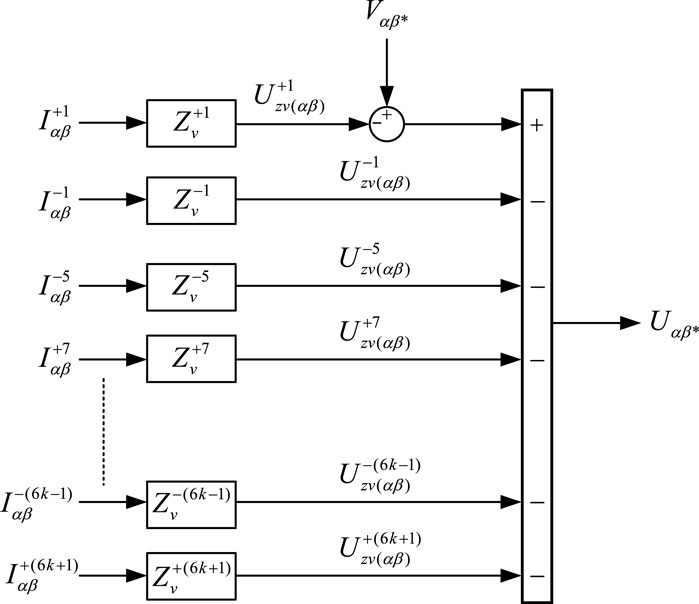
Figure 5. Control block diagram of virtual impedance control loop.
3.3 Voltage tracking control based on multi-parallel VPI controllers
3.3.1 Multi-parallel VPI controller
The block diagram of voltage control can be illustrated in Figure 6 in fundamental dq coordinate system. Where
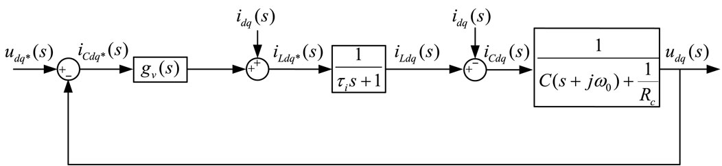
Figure 6. Block diagram of voltage control in fundamental positive dq reference frame.
According to (Xie et al., 2021), the dynamic characteristics of the inner current loop can also be equivalent to a first-order link with a time constant of
In this paper, the resistance of AC inductor is ignored, and the inner current loop adopts a P regulator. Assuming that the response time of the current loop is significantly less than that of the voltage loop, Figure 6 can be approximately equivalent to a single voltage loop control structure. The equivalent Figure 6 is then transformed into the hdq coordinate system, and the control block diagram is shown in Figure 7 (Bojoi et al., 2008).
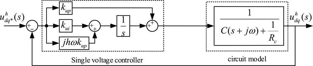
Figure 7. Block diagram of VPI controller in hdq coordinate system.
In Figure 7, the VPI controller proposed in (Bojoi et al., 2008) is adopted, which has better decoupling characteristics. The expression of the VPI controller shown in Eq. 11.
Where,
Substitute h = +(6 k+1) and h = −(6k−1) into (11) and transform them to fundamental positive dq coordinate system, we can obtain h = ±(6 k±1) harmonic voltage controller in fundamental dq coordinate system by adding the two controllers. Similarly, substitute h = 1 and h = −1 into (11), we can obtain h = ±1 voltage controller in αβ coordinate system by adding the two controllers.
According to Eq. 12,
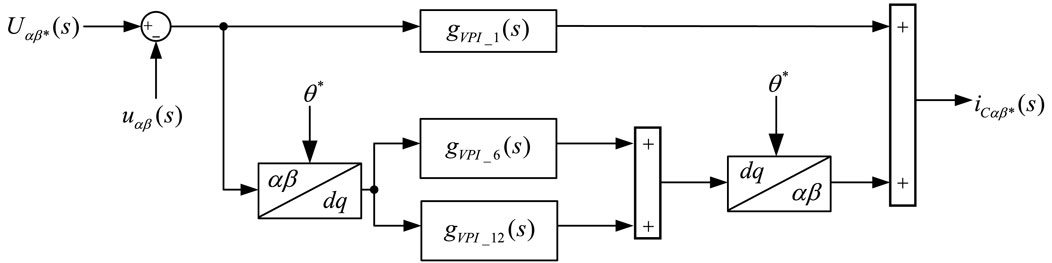
Figure 8. Control block diagram of multi-parallel VPI voltage controller.
3.3.2 Response characteristics analysis of voltage control loop
According to Eq. 12, the multi-parallel VPI controller
The expression of the closed-loop transfer function of the voltage loop is shown in Eq. 14.
The Bode diagram of voltage loop closed-loop transfer function in fundamental dq coordinate system can be drawn as shown in Figure 9. The characteristic of Gv(s) is similar to a band-pass filter, with unit gain and zero-phase offset at each target frequency. And the gain decays on both sides of the target frequency, which not only realizes the error-free control of the voltage command at the target frequency, but also has good attenuation performance at the non-target frequency.
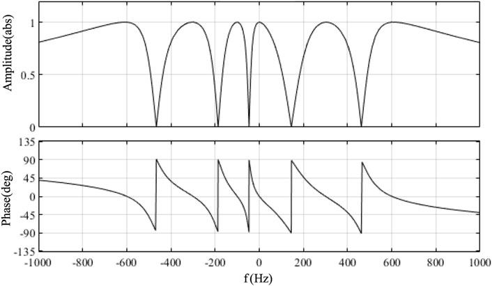
Figure 9. Bode diagram of closed-loop transfer function under multi-parallel VPI voltage control in fundamental dq reference frame.
To evaluate the decoupling and dynamic response characteristics of the multi-parallel VPI controller in this paper. According to Figure 7, the closed-loop transfer function of the VPI-based voltage control in hdq coordinate system can be written as Eq. 15. When taking
From the above analysis, it can be seen that the multi-parallel VPI controller can not only realize the error-free tracking of the voltage command, but also has good decoupling characteristics. The response characteristics of each harmonic voltage command can be equivalent to the first order link.
4 Current coordinated allocation and voltage quality optimization
4.1 Modeling of multi-VSG parallel system considering line impedance
The diagram of the multi-PCS parallel system considering line impedance is shown in Figure 10.
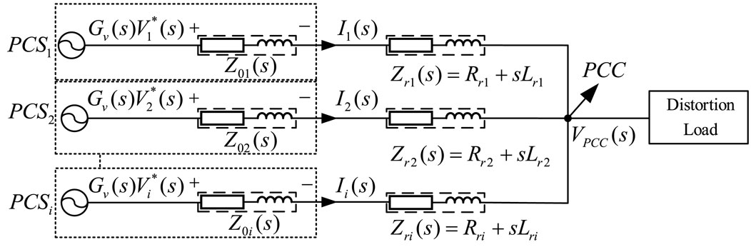
Figure 10. Diagram of multi-PCS parallel system considering line impedance.
According to Figure 10, the PCC voltage can be obtained as shown in Eq. 16, which implies that the harmonic distortion of PCC voltage mainly comes from harmonic voltage drop when distortion current
4.2 Coordinated distribution of multi-VSG output currents
There is no harmonic component in
Under multi frequency impedance reshaping control proposed in this paper,
Where,
From the above analysis, it can be seen that since both
According to Eq. 16, the distribution of harmonic current at hω satisfies:
According to Eq. 19, the distribution characteristics of negative sequence current and harmonic current of multi-PCS parallel system can be realized by adjusting the virtual impedance at each harmonic frequency. By adjusting the sum of harmonic virtual impedance and line impedance of each PCS to a certain proportion, the proportional distribution of negative sequence current and harmonic current can be realized.
According to Eq. 3, when
According to Eq. 5, when
4.3 PCC point voltage optimization
Substitute Eq. 18 into Eq. 16 he voltage at PCC can be represented by Eq. 22.
By setting the virtual impedance to a negative value so that the sum of the virtual impedance and the line impedance decreases, the harmonic voltage drop of the virtual impedance can offset part of the harmonic voltage drop of the line impedance, thus optimizing the PCC voltage quality. In order to improve the damping performance of the system, the inductive part of the line impedance can be completely canceled and the resistive part of the line impedance can be partially canceled. It should be noted that setting a negative virtual impedance can optimize the voltage quality at the PCC point, but the total impedance reduction will deteriorate the harmonic current distribution accuracy, and a compromise is needed in the setting.
5 HIL simulation platform verification
In order to verify the effectiveness of the method in this paper, a model of dual VSG parallel system is built in HIL simulation platform. The HIL simulation platform developed by ModelingTech Energy Technology Co., Ltd. is adopted, and its structure diagram is shown in Figure 11. The system parameters are shown in Table 1. Two groups of loads are selected for simulation, the first group is a three-phase series RL unbalanced load, Ra=Rb=3Ω, La = Lb = 0.12H and phase C is disconnected; the second group is a nonlinear load, which is simulated by a three-phase diode rectifier with a dc resistance of 15 Ω.
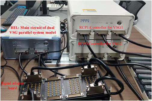
Figure 11. The structure of HIL platform for dual VSG parallel system model.
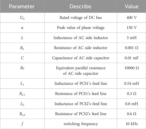
Table 1. The initial value of system parameters.
5.1 Performance validation of multi frequency impedance reshaping control
In order to verify the effectiveness and correctness of multi-frequency impedance reshaping control, the virtual impedance is set to a negative impedance opposite to feeder impedance. Under the above conditions, the virtual impedance harmonic voltage drop can completely offset the harmonic voltage drop of the feeder impedance, and the reshaping accuracy of the virtual impedance can be easily verified from the voltage quality of PCC. Meanwhile, the VSG impedance reshaping control strategy of literature (Göthner et al., 2019) is selected for comparison, which adopts LPF harmonic separation algorithm with only fundamental positive component feedforward compensation and the multi-parallel PI + QPR voltage controller. The control parameters in the comparison test are shown in Table 2.
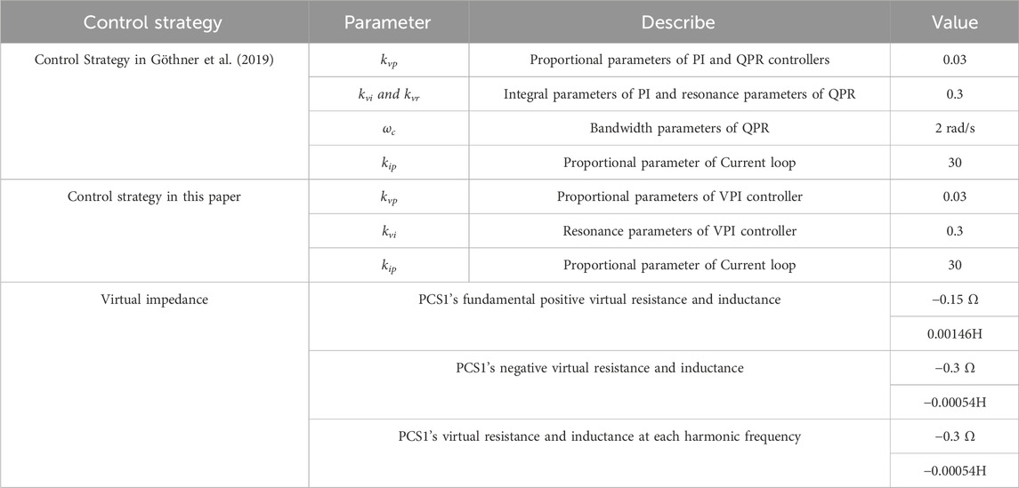
Table 2. List of parameters in the comparison test.
(a) Waveform of PCC voltage (left: control strategy in (Göthner et al., 2019), right: control strategy in this paper).
(b) FFT analysis of PCC voltage (left: control strategy in (Göthner et al., 2019), right: control strategy in this paper).
The harmonic currents extracted by harmonic separation algorithm used in (Göthner et al., 2019) are coupled, and the QPR controller is not able to achieve zero steady-state error.As a result, as showed in Figure 12 (left), 5th 7th 11th and 13th components of PCC voltage are not completely eliminated. Under the control strategy in this paper, the virtual impedance harmonic voltage output by PCS can be completely offset by the harmonic voltage of actual feeder impedance, and as showed in Figure 12 (right), the 5th, 7th, 11th, and 13th harmonics of the PCC voltage are completely eliminated.
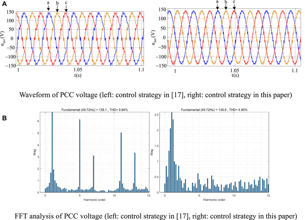
Figure 12. Comparison of HIL test results of impedance reshaping accuracy between the control strategy in Göthner et al. (2019) and the control strategy in this paper. (A) Waveform of PCC voltage (left: control strategy in Göthner et al. (2019), right: control strategy in this paper), (B) FFT analysis of PCC voltage (left: control strategy in Göthner et al. (2019), right: control strategy in this paper).
5.2 Performance verification of current coordinated allocation and voltage optimization
In order to verify the performance of multi-frequency virtual impedance reshaping control in current coordination distribution and voltage optimization, dual PCS parallel system is also tested on the HIL simulation platform, and the full-frequency-band fixed resistive virtual impedance control (Das et al., 2021) is selected for comparison. The parameters of the two control strategies are shown in Table 3.
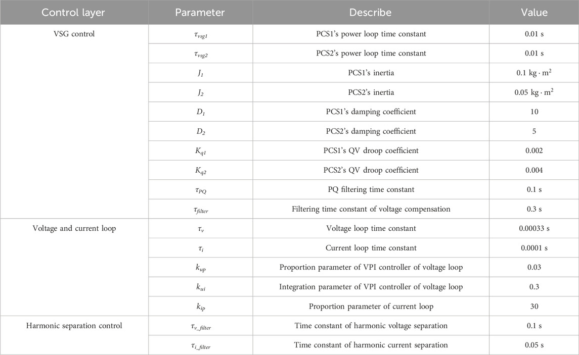
Table 3. Simulation parameters of dual VSG current coordinated control.
Under the fixed resistive virtual impedance control, the virtual resistance of PCS1 is −0.2 Ω, and the virtual resistance of PCS2 is −0.4 Ω. The virtual impedance parameters under the control strategy of this paper are shown in Table 4. Because D1:D2 = 2:1, Kq1:Kq2 = 1:2 and the sum of virtual impedance and feeder impedance satisfies the 1:2 relationship, from the above analysis, the ratio of active power, reactive power, and the harmonic current of the dual VSG, system should satisfy the relationship of 2:1.
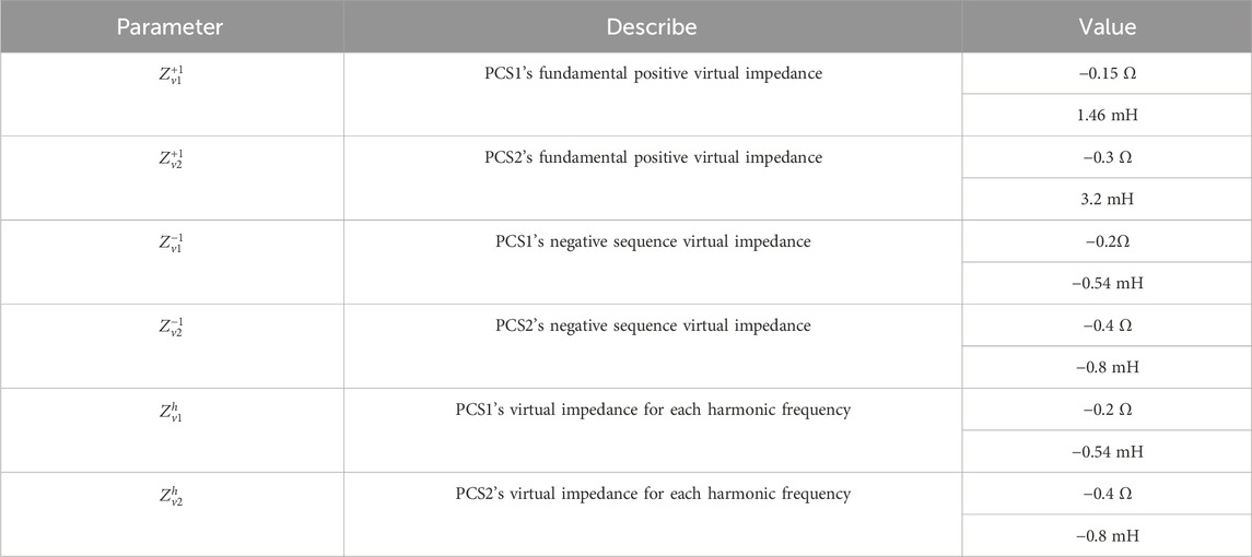
Table 4. Virtual impedance parameters for current coordinated control of dual VSG parallel system.
Figures 13A–D show the HIL test results of the dual PCS parallel system under fixed resistive virtual impedance control. Since the virtual impedance can only be reshaped as a fixed resistance value and cannot compensate the inconsistency of the line’s inductive impedance, the load current in Figure 13B cannot be distributed as needed. Active power and reactive power cannot be distributed according to the ratio of 2 : 1, and there is power oscillation. In addition, due to the harmonic amplification effect of the virtual impedance, the PCC voltage also has serious distortion.
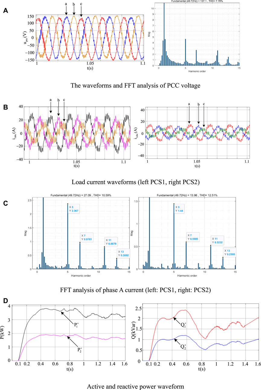
Figure 13. HIL test results of a dual PCS parallel system with fixed virtual impedance control. (A) The waveforms and FFT analysis of PCC voltage, (B) Load current waveforms (left PCS1, right PCS2), (C) FFT analysis of phase A current (left: PCS1, right: PCS2), (D) Active and reactive power waveform.
Figure 14A–D show the HIL test results of the dual PCS parallel system under coordinated current distribution and voltage optimization control in this paper. Due to the ratio of total impedance of PCS1 and PCS2 is 1:2, the load current of the two PCSs is distributed in a 2:1 ratio without phase offset. The distribution ratio of active power and reactive power between the two PCSs is also 2:1. FFT analysis shows that the current distribution ratio at the target frequency also satisfies the 2:1 relationship. In addition, there is no significant distortion in the PCC voltage, and the THD is 2.55%, indicating that the voltage quality has been significantly improved. The above results show that the proposed control strategy has significant performance improvement in current coordinated distribution and PCC voltage quality optimization.
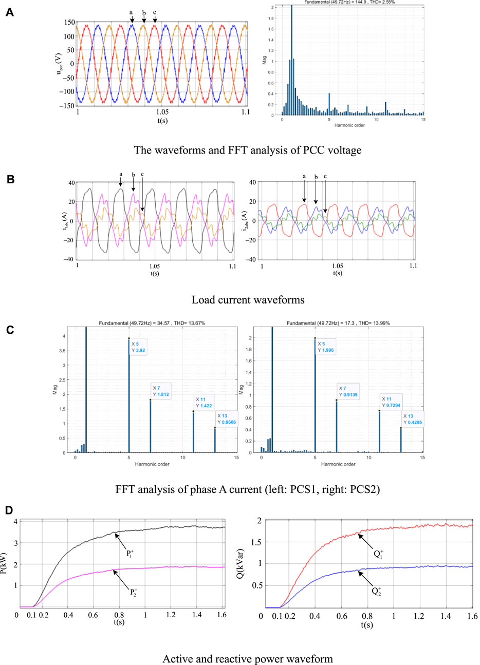
Figure 14. HIL test results of a dual PCS parallel system with multi frequency virtual impedance control proposed in this paper. (A) The waveforms and FFT analysis of PCC voltage, (B) Load current waveforms, (C) FFT analysis of phase A current (left: PCS1, right: PCS2), (D) Active and reactive power waveform.
6 Conclusion
In order to solve the problem of harmonic current sharing and voltage quality optimization of microgrid system with multiple VSGs interconnected by high impedance cables, the main contributions of this paper are as follows:A multi-frequency points VSG impedance reshaping control strategy combining the advantages of FCLPF harmonic separation algorithm and multi-parallel VPI controller is proposed in this paper. Among them, the harmonic separation algorithm based on FCLPF has the characteristics of bandpass filter at the target frequency, and the characteristics of notch at the non-target frequency. Based on each harmonic current extracted by FCLPF, the inductive and resistive impedance voltage drop of each harmonic frequency point can be independently constructed, and the coupling problem between the impedance voltage drop instructions of each frequency point can be solved. The voltage closed-loop transfer function of multi-parallel VPI voltage controller has unity gain and zero phase shift at each target frequency point, and the gain on both sides of each target frequency point decreases rapidly. It also has the decoupling characteristic of dq axis, which solves the problem that the traditional QPR voltage controller has low control accuracy at each harmonic frequency point. Based on the above characteristics, the multi-frequency VSG impedance reshaping control strategy proposed in this paper has advantages in the flexibility and accuracy of harmonic impedance reshaping, and can improve the precision of harmonic current coordination distribution and the voltage quality of PCC.
This paper provides a theoretical guidance for the multi-frequency impedance reshaping control of industrial energy storage converters, which is conducive to improving the current coordination distribution accuracy and PCC voltage quality of multi-PCS parallel systems under nonlinear and negative sequence loads. In the application of this control, the final performance of current coordinated distribution and voltage quality improvement depends on the estimation accuracy of the actual line impedance. In the future, further research can be carried out to improve the estimation accuracy, At the same time, this paper only considers the static distribution accuracy of distorted load, and does not consider the dynamic distribution problem of distorted load, which can be further studied in the future.
Data availability statement
The raw data supporting the conclusion of this article will be made available by the authors, without undue reservation.
Author contributions
LX: Conceptualization, Formal Analysis, Funding acquisition, Methodology, Resources, Supervision, Writing–original draft, Writing–review and editing. YuZ: Data curation, Methodology, Writing–original draft. YoZ: Formal Analysis, Writing–review and editing. YC: Validation, Writing–review and editing. BW: Validation, Writing–review and editing.
Funding
The author(s) declare that financial support was received for the research, authorship, and/or publication of this article. Supported by Zhejiang Provincial Science and Technology Plan Project (Grant No. 2023C01228).
Conflict of interest
Author BW was employed by company HRV ELECTRIC.
The remaining authors declare that the research was conducted in the absence of any commercial or financial relationships that could be construed as a potential conflict of interest.
Publisher’s note
All claims expressed in this article are solely those of the authors and do not necessarily represent those of their affiliated organizations, or those of the publisher, the editors and the reviewers. Any product that may be evaluated in this article, or claim that may be made by its manufacturer, is not guaranteed or endorsed by the publisher.
References
Alwaz, N., Raza, S., Ali, S., Bhatti, M. K. L., and Zahra, S. (2019). “Harmonic power sharing and power quality improvement of droop controller based low voltage islanded microgrid,” in 2019 International Symposium on Recent Advances in Electrical Engineering (RAEE), Islamabad, Pakistan, 28-29 Aug. 2019 (IEEE), 1–6.
Bojoi, R., Limongi, L. R., Roiu, D., and Tenconi, A. (2008). “Frequency-domain analysis of resonant current controllers for active power conditioners,” in 2008 34th Annual Conference of IEEE Industrial Electronics, Orlando, FL, USA, 10-13 Nov. 2008 (IEEE), 3141–3148.
Chen, S., Sun, Y., Han, H., Shi, G., Guan, Y., and Guerrero, J. M. (2023). Dynamic frequency performance analysis and improvement for parallel VSG systems considering virtual inertia and damping coefficient. ’’ IEEE J. Emerg. Sel. Top. Power Electron 11 (1), 478–489. doi:10.1109/jestpe.2022.3208249
Das, A., Shukla, A., Shyam, A. B., Anand, S., Guerreo, J. M., and Sahoo, S. R. (2021). A distributed-controlled harmonic virtual impedance loop for AC microgrids. IEEE Trans. Industrial Electron. 68 (5), 3949–3961. doi:10.1109/TIE.2020.2987290
Deng, F., Li, Y., Li, X., Yao, W., Zhang, X., and Mattavelli, P. (2022). A decentralized impedance reshaping strategy for balanced, unbalanced and harmonic power sharing in islanded resistive microgrids. IEEE Trans. Sustain. Energy 13 (2), 743–754. doi:10.1109/TSTE.2021.3130983
Dong, H., Yuan, S., Han, Z., Ding, X., Ma, S., and Han, X. (2018). A comprehensive strategy for power quality improvement of multi-inverter-based microgrid with mixed loads. IEEE Access 6, 30903–30916. doi:10.1109/ACCESS.2018.2826923
Gong, C., Sou, W.-K., and Lam, C.-S. (2021). Design and analysis of vector proportional–integral current controller for LC-coupling hybrid active power filter with minimum DC-link voltage. IEEE Trans. Power Electron. 36 (8), 9041–9056. doi:10.1109/TPEL.2021.3049834
Göthner, F., Midtgård, O.-M., Torres-Olguin, R., and Roldan-Perez, J. (2019). “Virtual impedance design for power quality and harmonic sharing improvement in microgrids,” in 2019 20th Workshop on Control and Modeling for Power Electronics (COMPEL), Toronto, ON, Canada, 17-20 June 2019 (IEEE), 1–7.
Huang, R., Zhang, M., Li, Z., Hou, C., Zhu, M., and Guo, M. (2020). “Influence of SOGI bandwidth on stability of single phase inverter in weak grid,” in IECON 2020 The 46th Annual Conference of the IEEE Industrial Electronics Society, Singapore, 18-21 Oct. 2020 (IEEE), 3779–3784.
Ji, J., Yang, L., Shi, J., and Yang, H. (2023). “Transient stability analysis of virtual synchronous generator considering current limitation,” in 2023 6th International Conference on Energy, Electrical and Power Engineering (CEEPE), Guangzhou, China, 12-14 May 2023 (CEEPE), 1306–1311.
Li, K., Cheng, P., Wang, L., Tian, X., Ma, J., and Jia, L. (2023b). Improved active power control of virtual synchronous generator for enhancing transient stability. IET Power Electron. 16 (1), 157–167. doi:10.1049/pel2.12371
Li, L., Zhou, K., and Tian, P. (2023a). A decentralized control with adaptive virtual inertia and damping combination for islanded cascaded-type VSG systems. IEEE Access 11, 139272–139283. doi:10.1109/ACCESS.2023.3340189
Moussa, H., Shahin, A., Martin, J.-P., Nahid-Mobarakeh, B., Pierfederici, S., and Moubayed, N. (2018). Harmonic power sharing with voltage distortion compensation of droop controlled islanded microgrids. IEEE Trans. Smart Grid 9 (5), 5335–5347. doi:10.1109/TSG.2017.2687058
Nguyen, K.-H., Nazeri, A. A., Yu, X., and Zacharias, P. (2022). “A novel modified-TOGI based PLL for the three-phase unbalanced and distorted grid conditions,” in 2022 24th European Conference on Power Electronics and Applications (EPE'22 ECCE Europe), Germany, 5-9 Sept. 2022 (Hanover), 1–10.
Qi, Y., Tang, Y., Potti, K. R. R., and Rajashekara, K. (2020). Robust power sharing control for parallel three-phase inverters against voltage measurement errors. IEEE Trans. Power Electron. 35 (12), 13590–13601. doi:10.1109/TPEL.2020.2993290
Qu, Z., Peng, J. C.-H., Yang, H., and Srinivasan, D. (2021). Modeling and analysis of inner controls effects on damping and synchronizing torque components in VSG-controlled converter. IEEE Trans. Energy Convers. 36 (1), 488–499. doi:10.1109/TEC.2020.3010049
Rasool, A., Fahad, S., Yan, X., Jiaoxin, J., Rasool, H., and Jamil, M. (2023b). A virtual parallel inductor approach for mitigating reactive power sharing error in a VSG controlled microgrid. IEEE Syst. J. 17 (1), 1363–1374. doi:10.1109/JSYST.2022.3180998
Rasool, A., Fahad, S., Yan, X., Rasool, H., Jamil, M., and Padmanaban, S. (2023a). Reactive power matching through virtual variable impedance for parallel virtual synchronous generator control scheme. IEEE Syst. J. 17 (1), 1453–1464. doi:10.1109/JSYST.2022.3188706
Vijay, A. S., Doolla, S., and Chandorkar, M. C. (2021b). Varying negative sequence virtual impedance adaptively for enhanced unbalanced power sharing among DGs in islanded AC microgrids. IEEE Trans. Energy Convers. 36 (4), 3271–3281. doi:10.1109/TEC.2021.3073150
Vijay, A. S., Parth, N., Doolla, S., and Chandorkar, M. C. (2021a). An adaptive virtual impedance control for improving power sharing among inverters in islanded AC microgrids. IEEE Trans. Smart Grid 12 (4), 2991–3003. doi:10.1109/TSG.2021.3062391
Wang, Z., Chen, Y., Li, X., Xu, Y., Wu, W., Liao, S., et al. (2022). Adaptive harmonic impedance reshaping control strategy based on a consensus algorithm for harmonic sharing and power quality improvement in microgrids with complex feeder networks. IEEE Trans. Smart Grid 13 (1), 47–57. doi:10.1109/TSG.2021.3112692
Wang, Z., Chen, Y., Wu, W., et al. (2021). Adaptive harmonic impedance reshaping current-sharing control method of parallel VSGs with different capacities and its stability analysis. Proc. CSEE 41 (24), 8571–8585. doi:10.13334/j.0258-8013.pcsee.201790
Xie, L., Guo, X., Wei, C., Zhang, Y., Chen, Y., Liang, C., et al. (2021). Adaptive droop control of the MTDC system with high-capacity energy storage based on dynamic and static power decoupling method. Front. Energy Res. 9, 710682. doi:10.3389/fenrg.2021.710682
Xu, H., Yu, C., Liu, C., Wang, Q., Liu, F., and Li, F. (2019). An improved virtual capacitor algorithm for reactive power sharing in multi-paralleled distributed generators. IEEE Trans. Power Electron. 34 (11), 10786–10795. doi:10.1109/TPEL.2019.2898990
Keywords: virtual synchronous generator, nonlinear and negative sequence loads, harmonic virtual impedance, coordinated distribution of harmonic currents, PCC voltage quality
Citation: Xie L, Zhang Y, Zhang Y, Chen Y and Wang B (2024) Current coordinated distribution and voltage optimization control for multi-VSGs system considering nonlinear and negative sequence loads. Front. Energy Res. 12:1369449. doi: 10.3389/fenrg.2024.1369449
Received: 12 January 2024; Accepted: 30 April 2024;
Published: 15 May 2024.
Edited by:
Ali Sohani, University of Rome Tor Vergata, ItalyReviewed by:
Fabio Corti, University of Florence, ItalyMohammad Hassan Shahverdian, K. N. Toosi University of Technology, Iran
Copyright © 2024 Xie, Zhang, Zhang, Chen and Wang. This is an open-access article distributed under the terms of the Creative Commons Attribution License (CC BY). The use, distribution or reproduction in other forums is permitted, provided the original author(s) and the copyright owner(s) are credited and that the original publication in this journal is cited, in accordance with accepted academic practice. No use, distribution or reproduction is permitted which does not comply with these terms.
*Correspondence: Youbing Zhang, eW91YmluZ3poYW5nQHpqdXQuZWR1LmNu