 JingWen Qi
 QingSong Ai1,2
 PengCheng Zhao
 Junkang Yang
- 1School of Nuclear Science and Technology, University of South China, Hengyang, Hunan, China
- 2Key Lab of Advanced Nuclear Energy Design and Safety, Ministry of Education, Hengyang, Hunan, China
- 3China Nuclear Industry Huawei Engineering Design and Research Co., Ltd, Nanjing, Jiangsu, China
Double-layer heat tubes have been designed to effectively reduce the occurrence of heat pipe rupture accidents. However, inter-tube thermal contact resistance can decrease heat transfer efficiency, thus hampering the heat dissipation in the primary loop system of lead-bismuth reactors. Therefore, optimizing the design of double-layer heat tubes is necessary. This work focuses on the double-layer heat exchanger of a lead-bismuth reactor and utilizes gallium-based graphene nanofluids as a thermal interface material to fill the gap between the heat tubes. Furthermore, the impact of the length, wall thickness, outer diameter, and spacing of heat tubes on the heat transfer performance of the double-layer heat exchanger with and without the nanofluids has been analyzed. The study aims to optimize the JF factor and cost-effectiveness ratio (CER). Genetic algorithms are employed to optimize and evaluate the heat transfer performance of the main heat exchanger based on the four aforementioned parameters. Consequently, a new design scheme is obtained for the double-layer heat exchanger, which increases the optimized overall heat transfer coefficient of the main heat exchanger by 5.79%, pressure drop in the primary loop by 2.32%, JF factor by 5%, and CER by 24.62%. These results demonstrate that the gallium-based graphene nanofluids can effectively enhance the heat transfer performance of the double-layer heat exchanger while reducing the likelihood of steam generator tube rupture accidents.
1 Introduction
Lead-bismuth reactors have garnered considerable attention due to their favorable neutron kinetics, thermal-hydraulics, and safety characteristics. According to the Generation IV International Forum (GIF), these reactors are poised to be the first commercially viable Generation IV reactors (Alemberti et al., 2014). The main heat exchanger plays a critical role in heat transport within lead-bismuth reactors, thus significantly impacting their economic viability and safety. However, their operating environment is harsh and characterized by high temperatures, substantial pressure differentials, high density, and rapid corrosion rates. Consequently, the heat exchange tubes in the main heat exchanger tend to be the weakest point in the primary loop system of lead-bismuth reactors. Thus, developing new heat exchange tubes that can exhibit superior heat transfer performance and exceptional reliability is necessary to mitigate the relatively high probability of failures, such as heat exchanger tube rupture and corrosion-induced flow blockage (Iskhakov et al., 2018). Closely bonded double-layer heat tube structures offer distinct advantages when applied to lead-bismuth reactors; for example, they prevent continuous crack propagation in the event of a rupture. Unlike single-layer tubes, cracks in double-layer heat tubes terminate at the interface between the two layers. Consequently, double-layer heat tubes can significantly reduce the likelihood of heat tube failure accidents (Jeltsov et al., 2018), making them an appealing design choice. However, the inter-tube thermal contact resistance decreases heat transfer efficiency, which is detrimental to the smooth dissipation of heat within the primary loop system of lead-bismuth reactors. Therefore, there is an imperative need to optimize heat tube design, mitigate inter-tube thermal contact resistance, and enhance heat transfer efficiency.
To effectively enhance the heat transfer performance of double-layer heat exchangers in lead-bismuth reactors, researchers from different countries have performed extensive exploratory studies and provided valuable insights. Guimei (WANG, 2014) investigated the impact of inter-tube thermal contact resistance on the heat transfer performance of a heat exchanger based on factors such as wall temperature difference, materials, tolerance fit, and surface roughness while proposing optimized fabrication schemes for double-layer tubes. Rozzia et al. (Rozzia et al., 2015) performed experimental research to investigate the impact of filling the gap between double-layer tubes with the AISI-316 powder on the heat transfer performance of the main heat exchanger. Meanwhile, Liu et al. (Liu et al., 2018) discovered that adding diamond powder inside double-layer tubes yielded superior heat transfer performance compared to that obtained by adding the 316L powder. The existing research has primarily concentrated on enhancing the heat transfer performance of heat exchangers in double-layer tubes by utilizing solid metal powders as fillers between the layers. However, the increase in heat transfer efficiency has been limited, thus significantly restricting the widespread application of double-layer heat exchangers in lead-bismuth reactors. Xiaohong et al. (Wang et al., 2021) proposed that by blending high-thermal-conductivity nanoparticles with ambient liquid metals such as gallium, rubidium, cesium, and mercury, high-performance metal thermal interface materials can be obtained, which tend to significantly reduce the thermal conductivity resistance between adjacent contacting objects and have broad application prospects in the design of double-layer tube-type heat exchangers for lead-bismuth reactors.
Gallium has stable chemical properties and can remain in liquid form under atmospheric pressure within the temperature range of 29.8°C–2,403°C. It also boasts high thermal conductivity, electrical conductivity, good fluidity, and a certain level of corrosion resistance. Importantly, it is non-toxic, making its use safer and more reliable. Therefore, it is considered an ideal liquid metal matrix material (Zhang et al., 2023). Nanoparticles are key to achieving excellent thermomechanical performance in nanofluids. Compared to other added nanoparticles, graphene is a two-dimensional layered structure material with high thermal conductivity, consisting of a single layer of carbon atoms arranged in a hexagonal lattice. As one of the best-known thermal conductive materials, it exhibits outstanding electrical, thermal, and mechanical properties (Kuang and Hu, 2013). Combining nanoscale graphene sheets with gallium particles results in nanofluids with a larger specific surface area, increasing the heat transfer interface, and thereby enhancing heat transfer efficiency. The stable properties of metallic gallium, along with its corrosion resistance, endow gallium-based graphene nanofluids with good stability, making them less prone to sedimentation or aggregation, which is beneficial for long-term stable thermal management.
This work focuses on improving the heat transfer performance associated with the main heat exchanger of a double-layer heat tube used in a lead-bismuth reactor. The gap between the double-layer heat tubes is filled with gallium-based graphene nanofluids, which serve as a thermal interface material. To assess the impact of this modification, the influence of heat tube length, wall thickness, outer diameter, and spacing on the heat transfer performance of the double-layer heat exchanger with and without the gallium-based graphene nanofluids filling is analyzed. This study aims to optimize the JF factor and cost-effectiveness ratio (CER). By utilizing a genetic algorithm, the four aforementioned parameters have been considered as optimization variables to evaluate and optimize the heat transfer performance of the main heat exchanger. Consequently, a new design scheme is obtained for the double-layer heat exchanger used in lead-bismuth reactors.
2 Theoretical model of the main heat exchanger
Currently, lead-bismuth reactors in several countries have entered the engineering and construction phase. The secondary loop of these reactors utilizes water and employs either flow boiling heat transfer or high-pressure single-phase heat transfer. This work primarily aims to explore the use of gallium-based graphene nanofluids as a thermal interface material, which can fill the gap between double-layer heat tubes. The study also involves the design and optimization of the proposed double-layer heat exchanger. To simplify the computational process, it is considered that the secondary loop in the main heat exchanger implements high-pressure single-phase heat transfer.
2.1 Heat transfer calculation of the double-layer heat exchange tube
Based on the heat balance, the coolant flow on both sides of the heat exchange tube is countercurrent; thus, the heat transfer relationship is as follows:
Where
The total heat transfer coefficient
Where
The heat flow transfer within the heat tube bundle, which contains liquid lead-bismuth, bears similarities to the flow heat transfer occurring within the fuel rods of the reactor core. Consequently, the heat transfer occurring on the shell side of the heat tube is computed using the flow heat transfer correlation proposed by Cheng et al. (Cheng and Tak, 2006) from the Karlsruhe Institute of Technology (KIT) in Germany; this correlation considers the heat transfer between the liquid heavy metal and the fuel rods.
For calculating the heat transfer coefficient in the fluid flow inside a circular channel under forced convection, the Dittus-Boelter correlation is employed.
2.2 Pressure drop calculation of the double-layer heat exchange tube
Since liquid coolants are considered incompressible fluids, their density can be considered to be the same at each point in the flow field. Since the coolant on both sides of the heat exchange tubes in the main heat exchanger does not undergo phase change during the flow process, the Darcy formula has been used to calculate the pressure drop along the single-phase flow:
Where
Owing to the sudden change in the cross-section of the flow channel at the inlet and outlet of the heat exchanger tube as well as at the inlet and outlet windows of the lead-bismuth reactor, a local pressure drop occurs, which can be calculated as follows:
Where
2.3 JF factor
To optimize the design of the main heat exchanger, it is desirable to obtain the best results at the least cost and ensure that the heat exchanger tube does not undergo breakage; this can be achieved by designing a main heat exchanger with the highest possible heat transfer efficiency and the lowest possible shell process pressure drop. The JF factor compares the heat transfer performance of the main heat exchanger with 1/3rd power of the pressure drop; the larger the JF factor, the better the overall performance of the main heat exchanger. Therefore, this study utilizes the JF factor as the evaluation index:
Where
2.4 Cost-effectiveness ratio
The JF factor is used as an evaluation criterion only for the performance of the main heat exchanger; however, it does not consider the actual engineering construction costs. Therefore, CER has been used to practically optimize the structural parameters of the main heat exchanger:
Where
2.5 Physical property model
The physical property models used in this work include the liquid lead-bismuth alloy, pressurized water, heat exchange tubes, and gallium-based graphene nanofluids. The main physical parameters of the liquid lead-bismuth alloy and pressurized water have been sourced from Fazio et al. (Fazio et al., 2015) and Wagner et al. (Wagner and Kretzschmar, 2008), respectively. Since the heat exchange tube is made of 316L stainless steel, the physical parameters of stainless steel data are used (Kim, 1975). Meanwhile, the physical properties of gallium-based graphene nanofluids are sourced from Xuan et al. (Xuan et al., 2003).
3 Research on the factors affecting the performance of the main heat exchanger
This study focuses on the main heat exchanger of China LEAd-based Reactor (CLEAR-I) (Wu et al., 2015). The flow direction of the coolant on the primary and secondary sides of the main heat exchanger is shown in Figure 1. The main heat exchanger has a tube-shell structure and comprises straight double-layered heat tubes arranged in a triangular pattern. The gap between the tubes is filled with the gallium-based graphene nanofluids.
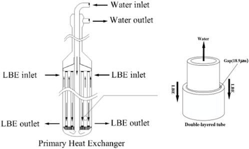
Figure 1. Schematic of the heat exchanger.
The parameters of the main heat exchanger during steady-state operation are shown in Table 1.
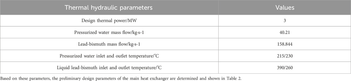
Table 1. Parameters of the main heat exchanger during steady-state operation.
The arithmetic mean deviation
3.1 Length of the heat exchange tube
The length of the heat exchanger tube

Table 2. Preliminary design parameters of the main heat exchanger.
Figure 2 shows that as the length
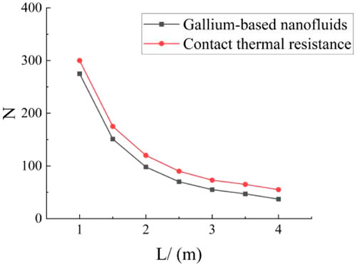
Figure 2. Variation in the number of heat exchange tubes with the length.
Figure 3 shows that the total heat transfer coefficient
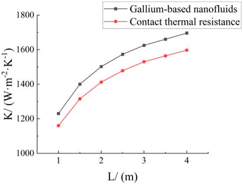
Figure 3. Variation in the total heat transfer coefficient with the length.
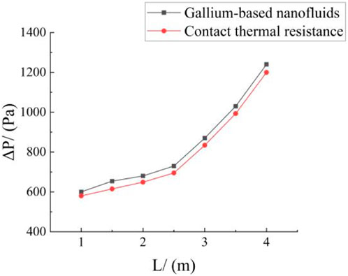
Figure 4. Effect of heat exchange tube length on shell-side pressure drop.
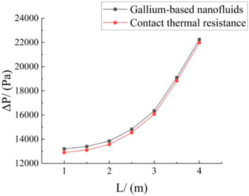
Figure 5. Effect of heat exchange tube length on tube-side pressure drop.
Figure 6 shows that when the secondary coolant flow rate remains the same, the JF factor decreases with increasing
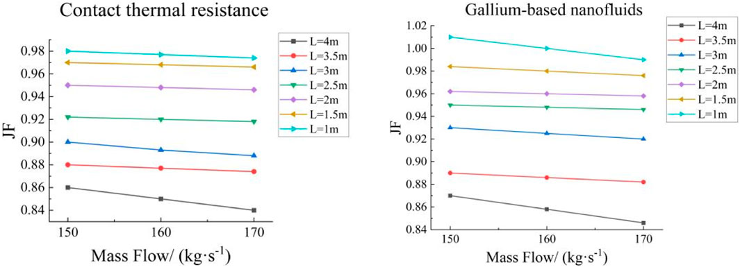
Figure 6. Effect of heat exchange tube length on JF factor.
3.2 Outer diameter and inner/outer diameter ratio of the heat exchange tube
The inner diameter
Figures 7, 8 show that when the rest of the structural parameters of the heat exchanger bundle remain unchanged, increasing the outer diameter
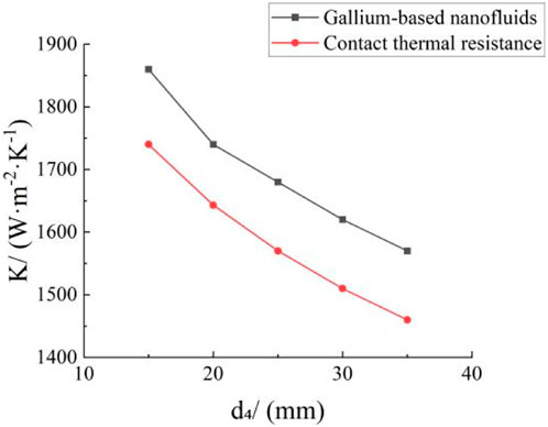
Figure 7. Variation in the total heat transfer coefficient with outer diameter.
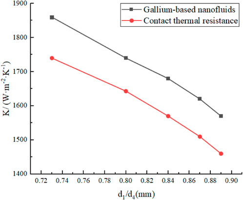
Figure 8. Variation in the total heat transfer coefficient with inner/outer diameter ratio.
Figures 9–12 show that augmenting the outer diameter
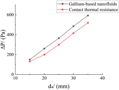
Figure 9. Effect of the outer diameter of the heat exchange tube on shell-side pressure drop.
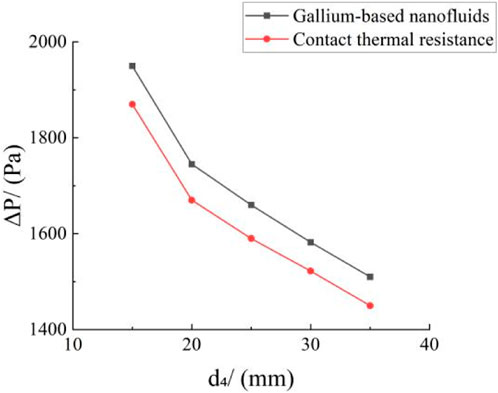
Figure 10. Effect of the outer diameter of the heat exchange tube on tube-side pressure drop.
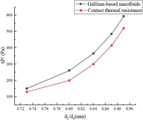
Figure 11. Effect of the inner/outer diameter ratio of the heat exchange tube on shell-side pressure drop.
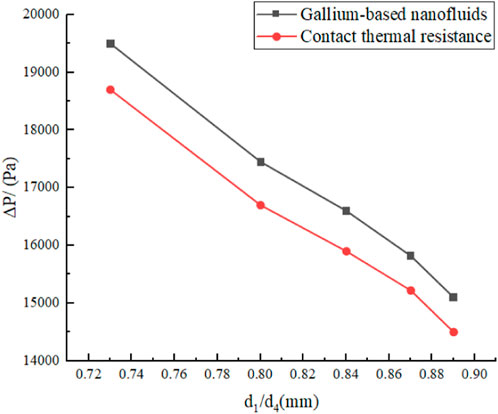
Figure 12. Effect of the inner/outer diameter ratio of the heat exchange tube on tube-side pressure drop.
Figure 13 shows that at a constant secondary coolant flow rate, the JF factor decreases with increasing
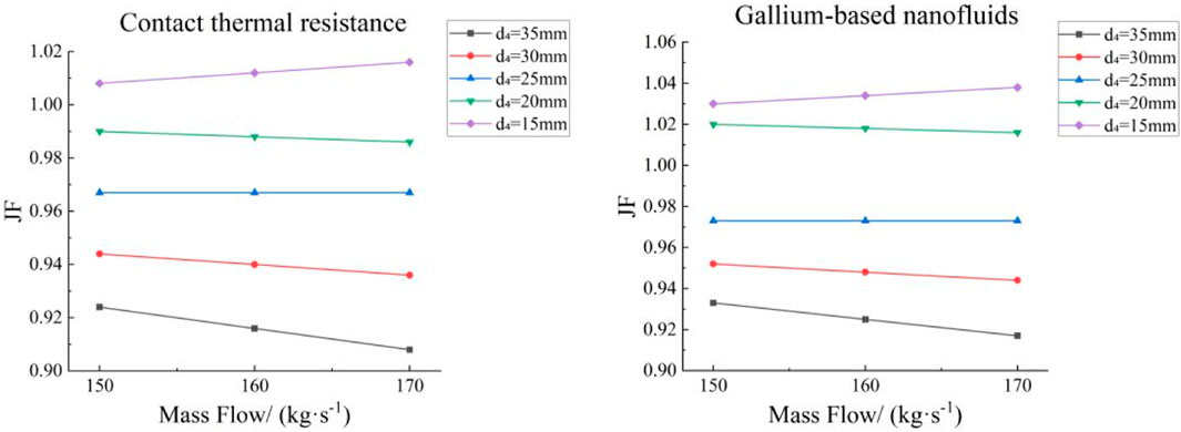
Figure 13. Effect of the outer diameter of heat exchanger tube on JF factor.
3.3 Wall thickness of the heat exchange tube
Several typical heat exchanger tubes with wall thicknesses of 3, 3.5, 4, 4.5, and 5 mm are used in this study, and the remaining parameters are shown in Table 2. As the outer diameter and tube spacing of the heat exchanger remain the same, the coolant flow cross section in a single circuit also remains constant; therefore, the shell pressure drop does not change much. These conditions allowed us to effectively study the influence of the wall thickness of the heat exchanger tube on the total heat transfer coefficient and the pressure drop in the tube for both main heat exchangers.
Figures 14, 15 show the variations in the total heat transfer coefficient and the pressure drop that occur across the tube due to a change in the wall thickness of the main heat exchanger. Figures 14, 15 show that as
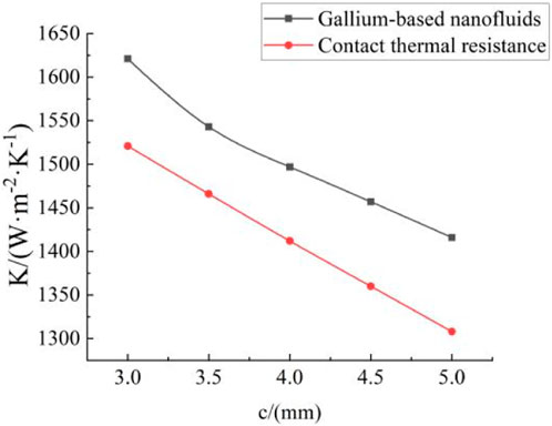
Figure 14. Variation in total heat transfer coefficient with wall thickness.

Figure 15. Effect of heat exchanger tube wall thickness on tube-side pressure drop.
Figure 16 shows the effect that the heat exchanger tube wall thickness has on the JF factor: when the outer diameter of the heat exchanger tube remains constant,
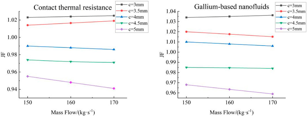
Figure 16. Effect of the heat exchanger tube wall thickness on the JF factor.
3.4 Spacing of the heat exchanger tubes
Tube spacing has a greater impact on the shell pressure drop than on the tube pressure drop; thus, this work studies the effect of tube spacing on the shell pressure drop of the two heat exchangers. The following heat exchanger tube spacings have been used in this study: 32, 34, 36, 38, 40, 42, 44, and 50 mm; the remaining parameters are shown in Table 2.
The effect of heat exchanger tube spacing on shell pressure drop and JF factor is shown in Figures 17, 18, respectively. Figure 17 shows that the shell pressure drop decreases non-linearly with increasing heat exchanger tube spacing
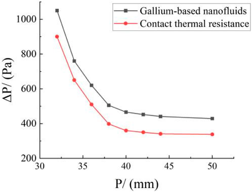
Figure 17. Effect of heat exchanger tube spacing on shell-side pressure drop.
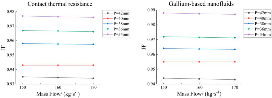
Figure 18. Effect of heat exchanger tube spacing on the JF factor.
In summary, for the same structural parameters, the JF factor of the heat exchanger tube with the nanofluids tends to be greater than that of the tube without any nanofluids, thereby ensuring that the main heat exchanger exhibits the best results at lower costs without causing any tube ruptures. Therefore, the geometry of the heat exchanger tube interstitially filled with the gallium-based graphene nanofluids has been optimized in the next section.
4 Optimization of the main heat exchanger size
4.1 Genetic algorithm
A genetic algorithm is an adaptive global optimization probabilistic search algorithm that simulates the evolutionary process of living organisms in nature and performs objective optimization based on size adaptation to find the optimal solution (Gen and Cheng, 1999). The genetic algorithm is based on the natural selection principle of “survival of the fittest and elimination of the unfit”, where genes are passed and varied among a group of individuals through genetic manipulation (e.g., selection, crossover, and mutation) to produce better-performing offspring. The algorithm repeats this process until a termination condition is met, such as reaching the maximum number of iterations or obtaining a sufficiently good solution. The genetic algorithm is widely used because it starts searching from multiple initial points, converges faster, covers a large area, and provides a globally optimal solution. Yang et al. (Yang et al., 2014) optimized the structural parameters in a shell and tube heat exchanger based on the genetic algorithm, such as tube diameter, wall thickness, and number of tubes, which significantly reduced the total heat exchanger cost. Mirzaei et al. (Mirzaei et al., 2017) used a multi-objective genetic algorithm to optimize the structural parameters of a heat exchanger, thereby improving its thermal efficiency by more than 28%.
In this work, the heat exchanger tube length, wall thickness, outer diameter, and spacing are coded as individuals, while the JF factor and CER are used as fitness functions. The maximum values are used as the target to continuously select, cross, and mutate, remove some individuals with low fitness, and generate the same number of individuals to maintain the total number of individuals; the iteration is stopped when the individual with the highest fitness is generated.
4.2 Variable scope
To more effectively select the variation range of parameters and speed up the convergence of optimal design, this work uses contribution ratio (CR) to evaluate the influence of each parameter on the comprehensive performance, which provides the optimization range of each structural parameter design according to its contribution level (Yun and Lee, 2000); CR is calculated as follows:
Where
The calculated CR of each parameter is shown in Figure 19, which reveals that spacing
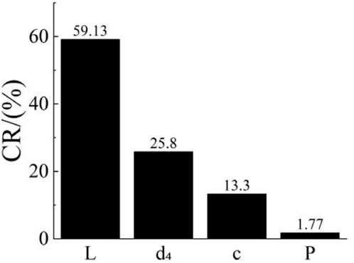
Figure 19. Contribution ratio (CR) of each parameter.
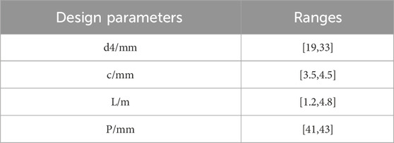
Table 3. Design parameter ranges of the heat exchange tube.
4.3 Optimization results
By using the maximum values of the JF factor and CER as objective functions, the outer diameter, wall thickness, length, and tube spacing of heat exchange tubes have been optimized using the genetic algorithm. The convergence process of the objective function value is depicted in Figures 20, 21 based on the number of iterations. The comparison of optimization results is shown in Table 4.
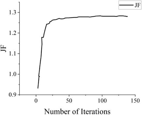
Figure 20. Variation curve of the JF factor with the number of iterations.
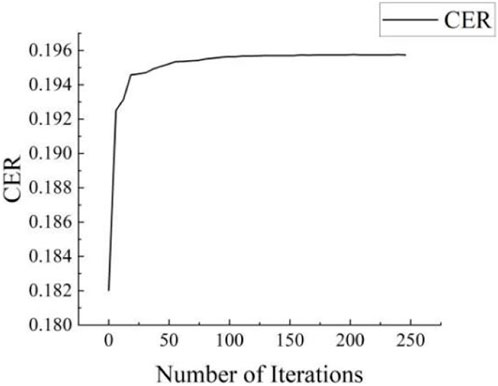
Figure 21. Variation curve of CER with the number of iterations.

Table 4. Comparison of heat exchanger performance before and after optimization.
This table provides valuable insights into the optimization results for Scheme 1 and Scheme 2 of the main heat exchanger.
In Scheme 1, optimization was performed to maximize the JF factor. Compared to the pre-optimization values, the overall heat transfer coefficient increased by 4.04%. Additionally, the pressure drop in the primary loop decreased by 23.01%, while the JF factor increased by 14%. This optimization approach aimed to improve the overall performance of the main heat exchanger by maximizing the heat transfer capacity while minimizing the pressure drop.
In Scheme 2, optimization was conducted to maximize CER. The overall heat transfer coefficient increased by 5.79% when compared to the pre-optimization value. However, the pressure drop in the primary loop increased slightly (by 2.32%). Nevertheless, CER significantly improved by 24.62%, which indicates that the heat transfer performance per unit cost is enhanced.
Compared with the double-tube heat exchanger with the same bundle structure optimization parameters but without using gallium-based graphene nanofluids, there is no significant change in the primary circuit pressure drop. For Scheme 1 and Scheme 2, the overall heat transfer coefficients are reduced by 42.32 W/(m2·K) and 59.67 W/(m2·K), respectively. Comparatively, the heat transfer capacity of the double-tube heat exchanger without gallium-based graphene nanofluid added in the gap decreases by approximately 2.70% and 3.56%. It can be seen that adding gallium-based graphene nanofluids in the gap between the double-layer heat exchange tubes can improve the heat transfer capability of the reactor, thereby reducing the temperature difference between different components of the reactor, and enhancing its safety and operational efficiency.
A comprehensive comparative analysis reveals that Scheme 2 strikes an optimal balance between heat transfer performance and cost-effectiveness. Although the pressure drop only slightly increases in Scheme 2, a greater improvement in heat transfer performance is achieved and the average cost ratio is minimized. This balanced optimization approach enhances the overall economic feasibility of the heat exchanger.
Based on the heat transfer performance and average cost, it can be established that Scheme 2 is the preferred design for the main heat exchanger. This design choice ensures a significant enhancement in heat transfer performance while exhibiting the best cost-effectiveness.
5 Conclusion
In this work, we propose to fill the gap between the double-layer heat exchanger tubes in a lead-bismuth reactor with a thermal interface material (gallium-based graphene nanofluids). Furthermore, the influence of the heat exchanger tube length, wall thickness, outer diameter, and spacing on the heat transfer performance is analyzed, and the results are compared to those obtained for the double-layer heat exchanger tube without the thermal interface material. Based on the optimization objectives of the genetic algorithm and the above-mentioned parameters, the heat transfer performance of the main heat exchanger is optimized and comprehensively evaluated; consequently, a new double-layer heat exchanger design scheme is obtained. The main research findings are as follows.
(1) For heat exchanger tubes with the same outer diameter, wall thickness, length, and spacing, adding the gallium-based graphene nanofluids leads to a better total heat transfer coefficient and higher heat transfer capacity; however, this addition increases the shell pressure drop, which is not conducive to achieving a natural circulation in the reactor. Nevertheless, the nanofluids increase the JF factor and lead to a better overall heat transfer performance.
(2) When other parameters are kept constant, increasing the heat exchanger tube length tends to increase the total heat transfer coefficient and the pressure drop in a single circuit, thereby strengthening the heat transfer capacity and weakening the natural circulation capacity. Furthermore, reducing the outer diameter of the heat exchanger tube can improve the total heat transfer coefficient and reduce the pressure drop in a single circuit, thus improving the heat transfer capacity and natural circulation capacity. Increasing the wall thickness of the heat exchanger tube tends to decrease the heat transfer capacity, while increasing the distance between tubes reduces the pressure drop in a single circuit, improves the natural circulation capacity, and reduces operation costs.
(3) The JF factor and CER are used as fitness functions and optimized using a genetic algorithm to obtain two solutions, which represent the maximum possible performance and the best overall performance of the main heat exchanger. The two solutions have been compared and the solution with the maximum CER value is selected as the optimal solution, which increased the total heat transfer coefficient by 5.79%, pressure drop in the first circuit by 2.32%, JF factor by 5%, and CER factor by 24.62%.
(4) The key technologies for optimizing the design of the double-layer heat exchanger include thermal performance optimization, improvement of bundle structure, and multi-objective optimization design. The aim is to enhance the overall heat transfer coefficient, reduce the pressure drop in the primary circuit, and improve economic feasibility while meeting optimization objectives.
Data availability statement
The original contributions presented in the study are included in the article/Supplementary material, further inquiries can be directed to the corresponding author.
Author contributions
JQ: Formal Analysis, Investigation, Methodology, Writing–original draft. QA: Investigation, Methodology, Validation, Writing–original draft. PZ: Conceptualization, Funding acquisition, Project administration, Supervision, Writing–review and editing. JY: Investigation, Methodology, Software, Validation, Writing–original draft. GW: Resources, Software, Validation, Writing–original draft.
Funding
The author(s) declare that financial support was received for the research, authorship, and/or publication of this article. This work is supported by Joint Fund of Ministry of Education for Equipment Pre-research (Grant No. 8091B032243). The authors would like to express their deepest gratitude to NEAL (Nuclear Engineering and Application Laboratory) Team for its help during this research.
Conflict of interest
Author GW was employed by China Nuclear Industry Huawei Engineering Design and Research Co., Ltd.
The remaining authors declare that the research was conducted in the absence of any commercial or financial relationships that could be construed as a potential conflict of interest.
Publisher’s note
All claims expressed in this article are solely those of the authors and do not necessarily represent those of their affiliated organizations, or those of the publisher, the editors and the reviewers. Any product that may be evaluated in this article, or claim that may be made by its manufacturer, is not guaranteed or endorsed by the publisher.
References
Alemberti, A., Frogheri, M., Hermsmeyer, S., Smirnov, L. A., Takahashi, M., Smith, C. F., et al. (2014). Lead-cooled fast reactor (LFR) risk and safety assessment white paper. Gen IV International Forum Online, Europe, UK
Cheng, X., and Tak, N. (2006). Investigation on turbulent heat transfer to lead–bismuth eutectic flows in circular tubes for nuclear applications. Nucl. Eng. Des. 236 (4), 385–393. doi:10.1016/j.nucengdes.2005.09.006
Fazio, C., Sobolev, V. P., Aerts, A., Gavrilov, S., Lambrinou, K., Schuurmans, P., et al. (2015). Handbook on lead-bismuth eutectic alloy and lead properties, materials compatibility, thermal-hydraulics and technologies-2015 edition (No. NEA--7268). Organisation for Economic Co-Operation and Development. Paris, France
Gen, M., and Cheng, R. (1999). Genetic algorithms and engineering optimization, John Wiley and Sons. Hoboken, NY, USA.
Iskhakov, A., Melikhov, V., Melikhov, O., and Yakush, S. (2018). Steam generator tube rupture in lead-cooled fast reactors: estimation of impact on neighboring tubes. Nucl. Eng. Des. 341, 198–208. doi:10.1016/j.nucengdes.2018.11.001
Jeltsov, M., Villanueva, W., and Kudinov, P. (2018). Steam generator leakage in lead cooled fast reactors: modeling of void transport to the core. Nucl. Eng. Des. 328, 255–265. doi:10.1016/j.nucengdes.2018.01.006
Kuang, D., and Hu, W. (2013). Research progress of graphene composites. J. Inorg. Mater. 28 (3):235–246. doi:10.3724/sp.j.1077.2013.12345
Liu, S., Jin, M., Lyu, K., Zhou, T., and Zhao, Z. (2018). Flow and heat transfer behaviors for double-walled-straight-tube heat exchanger of HLM loop. Ann. Nucl. Energy 120, 604–610. doi:10.1016/j.anucene.2018.06.016
Mirzaei, M., Hajabdollahi, H., and Fadakar, H. (2017). Multi-objective optimization of shell-and-tube heat exchanger by constructal theory. Appl. Therm. Eng. 125, 9–19. doi:10.1016/j.applthermaleng.2017.06.137
Rozzia, D., Fasano, G., Di Piazza, I., and Tarantino, M. (2015). Experimental investigation on powder conductivity for the application to double wall heat exchanger (NACIE-UP). Nucl. Eng. Des. 283, 100–113. doi:10.1016/j.nucengdes.2014.06.037
Wagner, W., and Kretzschmar, H. J. (2008). IAPWS industrial formulation 1997 for the thermodynamic properties of water and steam. Int. steam tables Prop. water steam based industrial formulation IAPWS-IF97, 52, 7–150. doi:10.1007/978-3-540-74234-0_3
Wang, G. M. (2014). Thermal-hydraulic optimal design and study of primary heat exchanger for lead alloy cooled natural circulation reactor. University of Science and Technology of China. Hebei, China.
Wang, X., Lu, C., and Rao, W. (2021). Liquid metal-based thermal interface materials with a high thermal conductivity for electronic cooling and bioheat-transfer applications. Appl. Therm. Eng. 192, 116937. doi:10.1016/j.applthermaleng.2021.116937
Wu, Y., Bai, Y., Song, Y., Huang, Q., Zhao, Z., and Hu, L. (2015). Development strategy and conceptual design of China lead-based research reactor. Ann. Nucl. Energy 87, 511–516. doi:10.1016/j.anucene.2015.08.015
Xuan, Y., Li, Q., and Hu, W. (2003). Aggregation structure and thermal conductivity of nanofluids. AIChE J. 49 (4), 1038–1043. doi:10.1002/aic.690490420
Yang, J., Oh, S. R., and Liu, W. (2014). Optimization of shell-and-tube heat exchangers using a general design approach motivated by constructal theory. Int. J. heat mass Transf. 77, 1144–1154. doi:10.1016/j.ijheatmasstransfer.2014.06.046
Yu, P., Zhu, R., and Yu, Z. (2002). Thermal analysis of nuclear reactors. Shanghai, China: Shanghai Jiao Tong University Press Publishing.
Yun, J., and Lee, K. (2000). Influence of design parameters on the heat transfer and flow friction characteristics of the heat exchanger with slit fins. Int. J. Heat Mass Transf. 43 (14), 2529–2539. doi:10.1016/S0017-9310(99)00342-7
Keywords: gallium-based graphene nanofluids, thermal interface material, double-layer heat exchanger tube, lead-bismuth reactor, optimized design
Citation: Qi J, Ai Q, Zhao P, Yang J and Wang G (2024) Design and optimization analysis of a new double-layer tube type heat exchanger for lead-bismuth reactors. Front. Energy Res. 12:1379747. doi: 10.3389/fenrg.2024.1379747
Received: 31 January 2024; Accepted: 14 March 2024;
Published: 28 March 2024.
Edited by:
Shichang Liu, North China Electric Power University, ChinaReviewed by:
Jie Li, Sun Yat-sen University, ChinaChenglong Wang, Xi’an Jiaotong University, China
Xiang Chai, Shanghai Jiao Tong University, China
Copyright © 2024 Qi, Ai, Zhao, Yang and Wang. This is an open-access article distributed under the terms of the Creative Commons Attribution License (CC BY). The use, distribution or reproduction in other forums is permitted, provided the original author(s) and the copyright owner(s) are credited and that the original publication in this journal is cited, in accordance with accepted academic practice. No use, distribution or reproduction is permitted which does not comply with these terms.
*Correspondence: PengCheng Zhao, cGVuZ2NoZW5nLnpoYW9AdXNjLmVkdS5jbg==