 G. V. Brahmendra Kumar
 K. Palanisamy
 Enrico De Tuglie2*
- 1School of Electrical Engineering, Vellore Institute of Technology, Vellore, India
- 2Department of Electrical Information Engineering, Polytechnic University of Bari, Bari, Italy
This paper demonstrates an enhancement of power quality for a photovoltaic (PV) system connected to the grid with a hybrid energy storage system (HESS). The proposed system utilizes a ramp-rate control (RRC) strategy to limit severe fluctuations in the PV power output. Battery storage is integrated to store surplus energy generated by the PV system and is used for continuous power application. A high-power density device, known as a supercapacitor (SC), is employed to mitigate transient fluctuations in the battery. The proposed system facilitates smooth PV power generation, stabilizes the DC bus voltage (VDC), and eliminates source current harmonics induced by non-linear loads. The Shunt Active Power Filter (SAPF) discussed in this paper serves two primary purposes. Firstly, it acts as a reactive power buffer, smoothing out fluctuations and reducing current harmonic distortions. Secondly, it enables active power injection into the grid, utilizing a specific renewable solar PV source. The efficiency of the modeled compensation system is demonstrated by the sinusoidal shape of the current and the compensation of reactive power (RPC). The targeted system showcases the effectiveness of the current setup by exhibiting low total harmonic distortion (THD). The multifunctional features of the proposed system were implemented using the MATLAB/Simulink software, and the results were validated using an OP5700 Hardware-in-the-Loop (HIL) test bench. This integration of distributed power generation capabilities not only enhances the overall power quality but also improves the efficient utilization of renewable energy resources (RESs).
1 Introduction
Renewable energy is a rapidly growing part of electricity generation because it is non-polluting and environmentally friendly. There is a global trend toward this energy source (Brahmendra Kumar and Palanisamy, 2019; Kumar and Palanisamy, 2023). Such electricity is used locally through conventional means, which are often not used if the local load is not strengthened. Integration of distributed RESs has recently gained interest in research due to the significance of the integration practices, particularly in terms of the impact on electrical power networks. Multiple DG sources can be linked together using the microgrid (MG). A MG is formed by the interconnection of distribution resources, ESSs, and loads. Distributed generation (DG) systems have the potential to improve distribution, but they also pose some risks, such as power imbalance, voltage variation, and so on. Conventional solar power utilization makes use of stand-alone PV systems, which supply energy directly. In grid-connected renewable systems, power is injected into the grid using Voltage Source Converter (VSCs) and a DC–DC converter. The renewable integration methods face problems in addition to unused power generated during the absence/reduction of load (Khan et al., 2022). The efficiency of RE will be impaired due to their high initial costs and seasonality. In order to resolve this problem, RESs interface power converters can be designed for multiple operations, such as correcting the system power factor, suppressing voltage fluctuations, and reducing current harmonics (Kumar et al., 2019; Kumar et al., 2021). When integrating RESs with the electric grid, the interface device between the sources and the grid plays a critical role as it can generate harmonic components that affect power quality (Panigrahi and Subudhi, 2017). To address this issue and optimize the utilization of RESs, a VSI can be constructed to inject active power from the RES along with ESS. HESSs are indispensable in modern MGs due to the intermittent and fluctuating nature of RESs and loads. In modern MGs, these HESS components are necessary for managing the intermittent behavior of RESs and loads. It also contributes to enhancing the power quality of the grid (Jasim et al., 2023).
The use of non-linear power electronic-based loads and switch mode power supplies has become more popular in present years. Consequently, the quality of delivered power has been negatively affected, leading to harmonic contamination and reactive power components that require compensation. Filters are increasingly being employed to mitigate harmonics and reactive power effects (Tareen and Mekhielf, 2018). The most common method of compensating for existing harmonics and reactive power is the use of passive filters, which are less expensive (Alfaris and Bhattacharya, 2019). The primary issue affecting power quality is the harmonic current and voltage profile. To address these concerns, the most commonly utilized device is an active power filter (APF) for shunt compensation. In (Kuznetsov et al., 2022; Wang et al., 2022), these authors propose a method based on a shunt APF that simultaneously addresses issues such as power factor, current imbalance, and current harmonics. If the PV system is associated to the grid, surplus energy can be fed into the grid once the maximum demand has been met. Consequently, when demand surpasses supply, extra energy is drawn from the grid. Therefore, PV energy functions as an additional power source (Parchure et al., 2017).
The use of sensitive electronic circuits in industries and homes, combined with the challenges posed by privatization and electric power systems, constitutes one of the major difficulties in the electrical industry. Harmonics lead to source voltage distortion and energy loss resulting from undesired current flow into the source. They can also lead to the failure of relays, switches, and other components. Therefore, various techniques must be available to mitigate harmonic effects (Devassy and Singh, 2019). The shunt APF generates equal magnitude and phase opposite harmonics of non-linear loads to cancel out the harmonic currents within the system. It is the most well-known method and is equipped with power electronic devices that have a fast response time and operate with flexibility. In (Beniwal et al., 2018), a shunt APF is used to control and operate a PV-battery-grid-connected system. The major drawback of the system is that sudden changes in load or source can stress the battery. Hence, the SC device is used to remove transient fluctuation in battery current, thereby extending the battery lifetime (Kumar and Palanisamy, 2020).
The control methods proposed in (Devassy and Singh, 2018; Zahedmanesh et al., 2020; Ray et al., 2022; Patel et al., 2023) pertain to the integration of shunt APF with solar PV. These methods offer many advantages, such as improving grid power quality and securing the grid-side disturbances of critical loads. However, they do not include ESS support for fluctuating PV power. Nonetheless, the combination of batteries and RESs allows systems to operate independently when the grid is unavailable and provides safe and continuous power to critical loads. The incorporation of the battery enables RES to supply stable power to the grid even when the PV array fluctuates (Saxena et al., 2017; Liang et al., 2023). However, the authors do not describe the operation and importance of the SC. The SC increases battery lifetime and system performance. Various active power topologies are combined with nonlinear loads to meet power quality requirements. Active filters with hybrid, series, and shunt topologies can provide flexible and high-quality offset for voltage and current distortions (Echalih et al., 2022). To improve the application of modern filtering methods, literature (Rahmani et al., 2015) suggests combining active filters with RESs such as wind and solar. Harmonic mitigation and the performance of APFs are critical to maintaining a constant DC link voltage (VDC). Consequently, numerous control approaches are discussed in the literature (Benchouia et al., 2015).
A PV-based D-STATCOM utilizes the SRF theory to improve power quality in (Golla et al., 2023). It enables better control of RPC, reduces voltage fluctuations, and optimizes solar power utilization. To compensate for reactive power, reduce harmonic distortions, and obtain maximum power from the PV module, a single-phase grid associating PV with an integrated SAPF is proposed in (Sharma et al., 2022). In (Pradeep Reddy et al., 2022), the discussion of the UPQC integrated PV system highlights numerous advantages, including improved grid power quality, protection of critical loads from grid-side disruptions, and increased fault ride-through converter capability during transients. According to a literature review, PV integrated SAPF offers several advantages over traditional methods, such as harmonic removal, stable VDC, and RPC.
The above-mentioned papers discuss power quality improvement in a renewable-grid integrated system based on the shunt APF capability. However, no control methods are discussed to mitigate changes in fluctuating PV power. Consequently, the size and cost of the ESS can increase. Additionally, sudden changes in the battery system can reduce the battery’s lifetime. The proposed work presented by the SC aims to mitigate sudden variations in the battery and thus increase the battery’s lifetime.
Figure 1 depicts a shunt-connected PV converter with a non-linear load that can operate in both shunt APF mode and real power injection mode. The SAPF is to be associated in parallel with the non-linear load, and the distribution network is to be linked to the point of common coupling (PCC). The output voltage value of the PV system can be adjusted using a DC/DC converter, and the p-q theory is employed to compute the current reference of the shunt APF. Furthermore, the inverter is utilized as an APF to compensate for reactive power and non-linear load harmonics (Abdullah et al., 2016). The PV interactive shunt APF system performs all of its functions during the day in intense sunlight. Power is required by the load at night, which is obtained from the distribution network when there is no sunlight. In contrast, the inverter system provides RPC, and harmonic currents are filtered (Dashtdar et al., 2022). The key contributions of this work are as follows:
• The shunt APF in this paper provides a reactive power buffer and eliminates current harmonic distortions. Additionally, it also injects active power into the grid from a given renewable solar PV source. It incorporates distributed power generation functionality while also improving power quality.
• The system remains stable under various circumstances, including changes in irradiation and load variations. Consequently, the VDC is maintained at a constant level even with sudden changes in load.
• The performance of the solar PV system is affected by insolation, time of the day, and temperature. System reliability is increased by the RRC, which mitigates PV power fluctuations.
• The battery-based ESS (BESS) is incorporated to provide continuous power flow into the system. The battery system is stressed as a result of the abrupt changes in battery power. Hence, the SC is used to respond to transients in the battery system.
• The combination of battery and SC devices improves the functionality of a grid-integrated system. The PV-HESS-grid network system has an inherent shunt APF capability and maintains the grid voltage and current THD within the IEEE-519 standard limits.
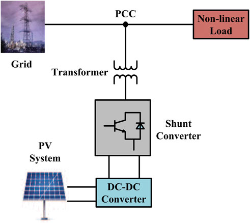
Figure 1. Shunt converter fed with a PV system.
This paper is structured as follows: Section 2 outlines the methodology, which includes subsections on the configuration of the SAPF with a PV system, the configuration of the proposed method, and the control scheme of the proposed system. In Section 3, the results and discussion are provided, along with the implementation of the Hardware-in-the-Loop (HIL) system. The simulation and HIL experimental test-bench results of the proposed control scheme, both with and without a controller, are also presented in this section. Finally, Section 4 contains the conclusions.
2 Methodology
2.1 Shunt APF configuration
A shunt APF is a converter that combines the switching network as well as the filter components. Figure 2 depicts the model circuit for the shunt APF configuration. The high-frequency switch power converter is generally used to control the desired current flow between the DC side and the AC side. The power converter incorporates semiconductor switches as well as storage devices. The typical power converter is basically a VSI, which is low in cost, low in loss, and easy to implement (Fabricio et al., 2018; Kumar and Bansal, 2019). The power filter’s structure is based on the VSI control technique, which includes a DC-storage capacitor and the connection of the inverter output to the non-linear load. The anti-parallel diodes are connected to the IGBTs in each of the switches to allow the flow of current in either direction.
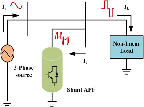
Figure 2. Model circuit for shunt APF.
The current control scheme is used to control the power flow in the VSI. To transfer active power from RES to the grid and loads, a current-controlled VSI is used. The AC side of the VSI is connected to the grid via the PCC and the DC side is connected to the PV via the HESS. The current-controlled VSI is used to shunt APF to enhance the power quality of the electrical system. The power converter is used to remove current harmonics and compensate for reactive power required by non-linear loads. As a result, grid currents become sinusoidal with a unity power factor. The shunt APF can detect the harmonic currents due to the non-linear load. Then it injects an equal magnitude current in the opposite direction (Hoon et al., 2018), called a compensation current (IC). It decreases harmonics in load currents (IL) caused by non-linear loads.
2.2 Configuration of the proposed system
The structure of the system consists of a PV system, BESS, SC, VSI, non-linear load, ripple filter, and DC-bus capacitor. The grid-connected PV system with a HESS configuration is shown in Figure 3. The PV-SAPF system is connected to a three-phase, four-wire power supply. It is designed and simulated for a three-phase grid-integrated PV system and with loads at the PCC. The proposed method aims to provide better compensation and a simpler structure while reducing the number of three-phase power switching devices. The system must extract grid voltage and load current fundamentals.
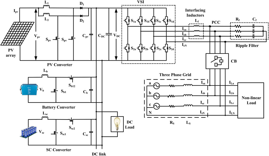
Figure 3. Configuration of a renewable-grid connected MG with HESS.
On the DC grid side, a PV system is associated with an interleaved boost converter (IBC) to obtain peak power from the PV system, and HESS is utilized to balance average and transient power flow. The IBC is used in the system to minimize current ripples, conduction losses, and switch voltage stress. Hence, the system efficiency is improved by saving energy (Kumar and Palanisamy, 2019; Kumar et al., 2020). The BESS and SC are linked to the DC bus with bi-directional converters. Renewable power/load variations affect VDC dynamics. As a result, the SC unit supports the transient power requisite at the DC link, while the battery and grid share average power. It regulates VDC quickly. If the SC is not linked to the system, the battery/grid should supply or absorb the transient power. Consequently, VDC requires longer time to stabilize. Hence, the SC control scheme is crucial for improving VDC dynamics.
Nonlinear and unbalanced loads on the AC grid side are connected to assess the additional functionalities of the proposed scheme, including harmonic compensation, RPC, load balancing, and power factor correction in grid-connected mode. Power quality issues such as reactive power and harmonics from the load can be mitigated using a shunt compensator. The PV system is integrated with the SAPF system at the DC-link. In the PV-SAPF setup, the shunt compensator not only compensates for losses but also harnesses power from the solar PV array. Three nonlinear loads in each phase are simulated using an uncontrolled bridge rectifier with an R-L load. To minimize current and voltage fluctuations, interfacing inductors (Lf) and ripple filters (Rf, Cf) are utilized to connect to the PCC.
Solar PV array power production fluctuates with changes in the time of day, temperature, and insolation. To mitigate these variations, HESS are integrated into solar PV-grid-connected MG systems (Zahedmanesh et al., 2020; Patel et al., 2023). The HESS, connected to the DC link of a VSC through a bidirectional converter, proves highly effective. Figure 4 illustrates a power flow chart for a solar PV-HESS grid system. Excess power from the solar PV is directed to the grid after meeting the load requirements, and any surplus is used to charge the battery during off-peak load hours. During peak load times, both the PV and HESS contribute power to the grid. If the PV supply falls short of meeting the load demand, the HESS provides additional power during peak load times. Conversely, during off-peak load periods, the grid supplies power to the load. Furthermore, if the BESS reaches its maximum discharge limit, the grid must supply the load demand even during peak load hours.
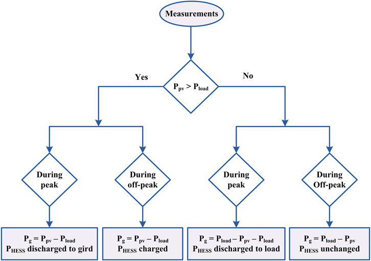
Figure 4. Power flow chart of a PV-HESS-grid connected system.
2.3 Control scheme
2.3.1 PV power variations and ramp-rate control
Various system operators have distinct requirements regarding the connection of Renewable Energy Source (RES) power stations to the grid. Reference (Brahmendra Kumar et al., 2018) emphasizes the need for smoothing RES fluctuations and implementing ramp-rate limits for grid connection of the power plant. The RRC is employed to ensure the smooth solar output depicted in Figure 5.
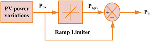
Figure 5. RRC block diagram.
There have been recorded normal and severe variations of up to 70% and 90%/min, shown in Figure 6A, B. Therefore, in order to smoothen the PV output power, compliance with these regulations includes the combination of PV generators with ESS technologies to add or subtract power to or from the PV supply. Figure 7 depicts abrupt decreases from full power to zero, which are obviously the maximum possible fluctuations. Power and energy storage capacity have simply been presented from a few rather direct and intuitive calculations regarding PV output profiles. An analytical theoretical model has been proposed and validated for this fluctuation scenario by comparing the related battery requirements with those obtained from detailed simulations using real power data.
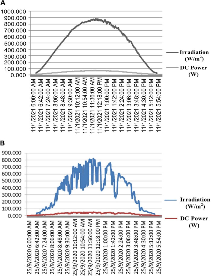
Figure 6. (A) Normal irradiation variations on a day, (B) Severe irradiation variations on a day.
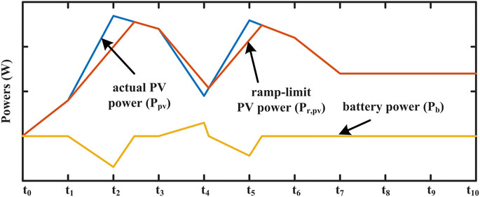
Figure 7. BESS characteristics using RRC.
The RRC sets the ramp-rate value, which increases the reliability of the grid and reduces power fluctuations (Gundumalla and Eswararao, 2018). The BESS power (Pb) is measured by the difference between the PV power (Ppv) and the ramp-limit power (Pr,pv). Figure 7 depicts the characteristics of BESS using RRC. The BESS is charged when the Ppv surpasses the ramp capacity. In addition, when the PV power falls below the power of the ramp, the BESS is discharged.
2.3.2 Control structure of PV and HESS
Figure 8 illustrates the reference currents for the PV, battery, and SC. The PV reference current generation through the RRC. The PI current controller compares the PV reference current (Ipvref) with the IBC’s actual current (Ipv), which is then passed to the PI controller to generate the signals. The reference current generation and LPF are used in the battery converter control. The low-pass filter (LPF) generates the battery net current (Inet), which is divided into the average value (Iavg) of net current for the battery and the transient component of current (Itrs) for the SC. The Iavg is calculated using the given Eq. 1 (Rauf and Khadkikar, 2015),
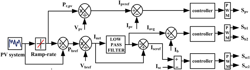
Figure 8. Control diagram for PV system with HESS.
The modulating signal for the PV and battery converter are taken from the following Eqs 2, 3,
As shown in Figure 8, the supercapacitor control loop consists of current control and reference current generation (Isc,ref), and The reference current generation block extracts transient current component of Itrs. The SC reference current (Iscref or Itrs) is generated by the difference between (Inet) and (Iavg), as given below (Rauf and Khadkikar, 2015),
The control block uses the reference current derived in (4) and other input variables to determine the supercapacitor pack’s operating mode. The current control loop uses the SC’s reference current (Isc,ref) to generate switching pulses. The following Eq. 5 can be used to derive the SC converter’s modulating signal (δsc):
Where Kp, Ki, to, Ib,e or sc,e, Tb or sc are proportional and integral time constants, arbitrary time constant, battery or SC error current, and SC block average time window.
Accurate state of charge (SoC) calculations is crucial for battery-powered systems as they significantly impact battery performance. Precise SoC estimations not only safeguard the battery by preventing overcharging, but also extend its lifespan while enhancing overall system accuracy and energy efficiency (Saxena et al., 2017). The SoC is typically determined using the count-coulomb method, and the following Eq. 6 describes the SoC for the battery.
Where SoCbin, CNb and Ib represent the initial SoC, nominal capacitance, and current of the battery, respectively.
2.3.3 p-q theory-based control strategy
The instantaneous p-q theory is mainly based on instantaneous power measurements in the time domain. It primarily applies to a 3-phase 3-wire system or a 3-phase 4-wire system. It is evaluated on a time-domain basis. Therefore, it is suitable not only for stable conditions but also for transient conditions (Abdullah et al., 2016). In an instantaneous theory of real and reactive power, the p-q theory is primarily used in the design of controllers for active power filters, and power conditions based on power electronic devices (Barva and Arkdev, 2023). The p-q principle first transforms the voltages and currents linearly. Then it determines the instantaneous power in those coordinates from the abc-coordinate system to the 0αβ-coordinate system. Figure 9 displays the block diagram and flow chart of the p-q theory. The p-q theory is effective for designing active filter controllers as it converts voltage and current from abc to αβ0 coordinates, enabling the determination of instantaneous power.
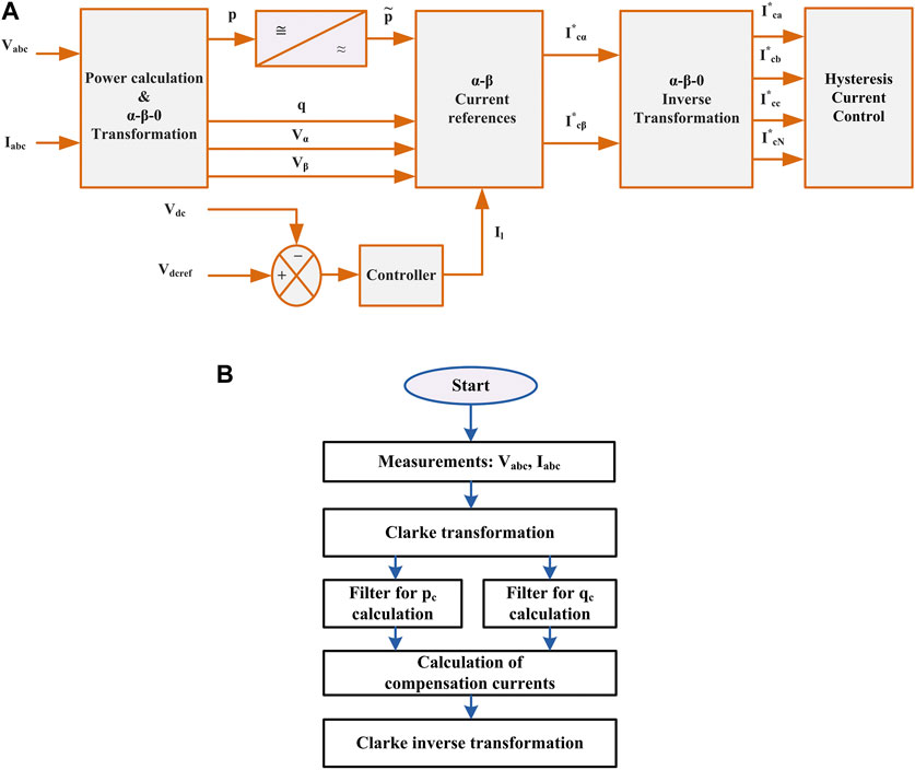
Figure 9. p-q method: (A) block diagram, (B) flow chart.
The reference current is measured using the p-q methodology. By using the Clark transformation, the source voltages and load currents will be converted from abc coordinates to 0αβ coordinates in Eqs 7, 8 (Belaidi et al., 2013; Wategaonkar et al., 2018), respectively.
The matrix format can be used to represent instantaneous active/real and reactive/imaginary powers in the following Eq. 9.
The active (p) and reactive (q) instantaneous powers, which includes AC and DC values referring to the fundamental and harmonic currents, are given by Eqs 10, 11 (Wategaonkar et al., 2018),
Where
The compensation currents obtained in Eqs 13, 14 in abc coordinates using Eqs 8, 12 are as follows (Wategaonkar et al., 2018),
ICN is a combination of three 3-phase compensation currents. The voltage control loop provides a basic proportional-integral (PI) function. The PI control is aimed at maintaining the VDC at the reference voltage (VDCref) level and providing the magnitude of the reference current signals (Il). The active power in this loop is kept balanced between the grid, load, and DC bus of the VSI. If there is a power imbalance in the network, a voltage deviation of the reference voltage is present at the DC bus. The voltage control loop appropriately adjusts the grid active current amplitude and retrieves the VDC according to the VDCref level. To keep the DC voltage from changing and to keep it at a constant value with a fixed reference value, an extra flow of energy to and from the capacitor is needed. The surplus real power is denoted as Pl and is incorporated to compensate for real power (p), which is subsequently forwarded to the current reference calculation block along with compensating reactive power (q).
2.3.4 Control structure of a shunt compensation
The control method for SAPF is depicted in Figure 10A, B, where the shunt APF reference is required grid current which must be sinusoidal and UPF. The active fundamental component is extracted by the shunt compensator in order to compensate load current. The shunt compensator operates by extracting the active component of the load current.
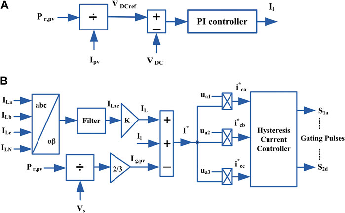
Figure 10. (A) Control diagram of loss current component (B) Control diagram for shunt APF.
The active current injected into the grid (I*) is calculated as Eq. 15,
Where IL is the load active current component, Il is the loss current component due to switching, conduction, filter, and inductor losses, and Ig,pv is the grid current corresponds to the ramp-limited PV power. The Eqs 16, 17 represent the equivalent grid current for load active power.
Where V*L, Vs are the reference load voltage and PCC voltage magnitudes.
The Ig,pv is taken from the Eq. 18 below,
The DC-link voltage (VDC) and capacitance (CDC) are calculated based on the following Eqs 19, 20,
Where “m” is the modulation index, “k” is a dynamic energy change factor, denote ‘a' as the overloading factor, ‘Vph’ as the per-phase voltage, ‘t' as the minimum time required to achieve steady state following a disturbance, and ‘Ish’ as the shunt-compensator current per phase. The size of the CDC is determined by the power demand and the VDC.
The shunt compensator inductor rating relies on ripple current, switching frequency (fsw), and VDC. The equation of the interfacing inductor (Lf) is given in Eq. 21,
Where IL,r is ripple current of the inductor (5%–20% of Ish,rms). The instantaneous reference currents in Figure 11 are derived by multiplying the magnitude reference of the SAPF with the unit templates of the PCC voltage. The current control references in Figures 9, 10 are generated in the proposed model using the p-q theory computational block and the hysteresis current controller block. This method is stable, fast, accurate, and limits peak current. To regulate the shunt compensator, the error between (i*ca, i*cb, i*cc) and (ica, icb, icc) is passed to the controller, which produces gate pulses. The generated gate pulses from the hysteresis controller are fed to the inverter.
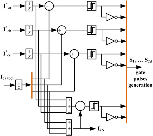
Figure 11. Hysteresis controller.
3 Results and discussion
3.1 HIL implementation
HIL systems are widely employed in engineering applications for conducting real-time simulation tests prior to pre-prototyping. Engineers utilise RT simulations for power electronics and motor drives as a phase in the design process, either to simulate the entire system in RT, or to connect a portion of the system to the rest of the system in what is generally referred to as a “HIL” application.
3.2 Control of HIL system
For a power electronics control system, the plant (power source, converter, and load) is typically made up of a controller and the power circuit (Figure 12). In closed-loop systems, sensors and actuators play a vital role by transmitting feedback signals from the plant to the controller and by regulating the signals transferred from the controller to the power switches (such as the firing pulse unit and gate drives).
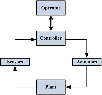
Figure 12. Control system block diagram.
3.3 Design process of HIL system setup
The design process for most engineering projects, including power electronics, consists of four steps: requirements and specifications, design, execution, and validation.
First, text-based documentation communicates and manages design information. Text-based documentation is hard to understand and prone to interpretation errors (Figure 13A).
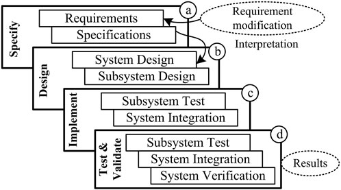
Figure 13. HIL design process.
In a typical project, design needs may vary due to addition or modification (Figure 13B). This requirement change would require new development and verification, and the following iterative loop is inadequate and often affects development and testing times.
Developing code manually from specification and requirements documents is time-consuming and prone to implementation problems (Figure 13C). The system changes are tracked to assure their implementation.
Finally, in this design process, obtaining a system result during initial stages is challenging (Figure 13D). Design and requirements problems are identified late in the design cycle, causing delays in the process, and adversely affecting the project.
The laboratory is equipped with OPAL-RT stacks on the HIL test bench, and its flow chart and experimental setup are shown in Figures 14, 15. Stacks can swiftly construct prototypes and hardware synchronization quickly. In the RT-LAB environment, the plant and controller are configured within OPAL-RT system to operate at physical clock time. The rapid Nano-to-microsecond sampling rate of OPAL-RT constitutes a real-time dynamic system. The OP5700 HIL test bench, RT-LAB system software, MSOX3014A, PCBE06-0560 control board, probes, and connecting wires are used to validate the simulated results. The user’s PC manages the RT-LAB Digital Simulation (RTDS) commands. The model is modified, built, loaded, and executed using the RT-LAB application.
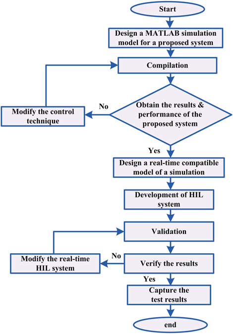
Figure 14. Flow chart of the proposed system operation using the HIL test-bench.
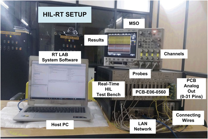
Figure 15. HIL experimental set-up.
3.4 System parameters
The PV, battery, and SC parameters are presented in Table 1. The system comprises a three-phase AC source voltage rated at 415 V with a frequency of 50 Hz, along with non-linear load resistance and inductance parameters of 5 Ω and 10 mH. The minimum required VDC is 677.7 V for a line voltage of 415 V. The VDC is set at approx. 700 V.
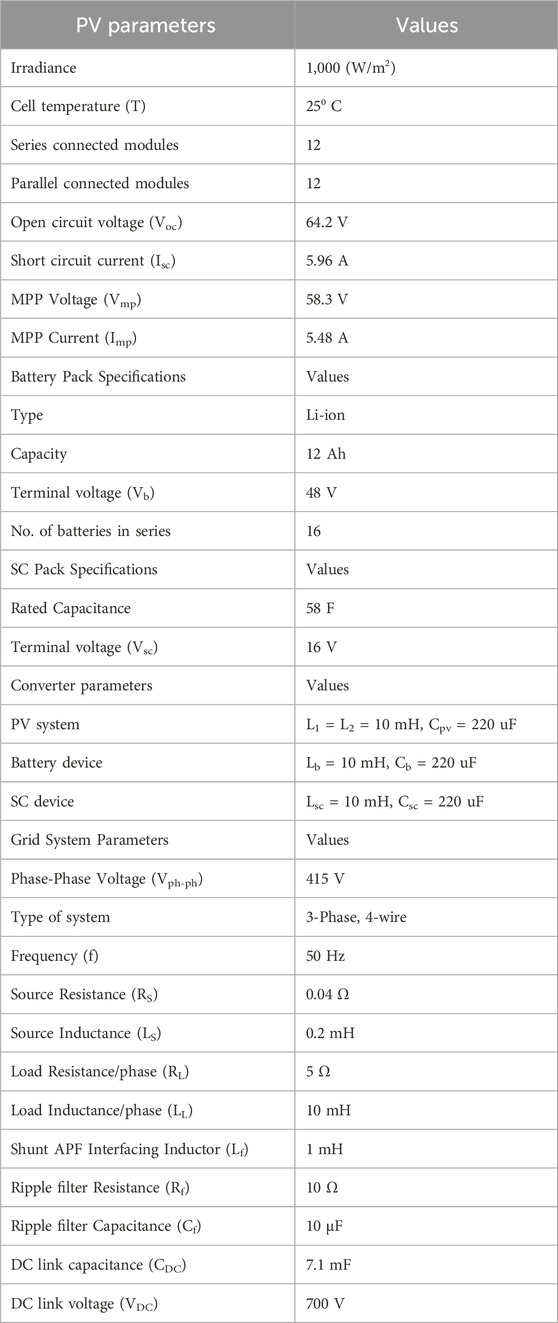
Table 1. System parameters.
3.5 Simulation results
The SAPF performance is verified using MATLAB-based Simulink and simulation results are depicted in Figure 16. Three-phase 415 V and 50 Hz are considered. The SAPF is linked to the load via three-phase circuit breaker (CB) that is initially open, and the results are presented in Figure 16.1. The SAPF connects to a non-linear load and uses a diode rectifier to test its performance. The nonlinear voltage and current results are presented in Figure 16.3. SAPF performance is analysed in nonlinear and unbalanced conditions through THD performance.
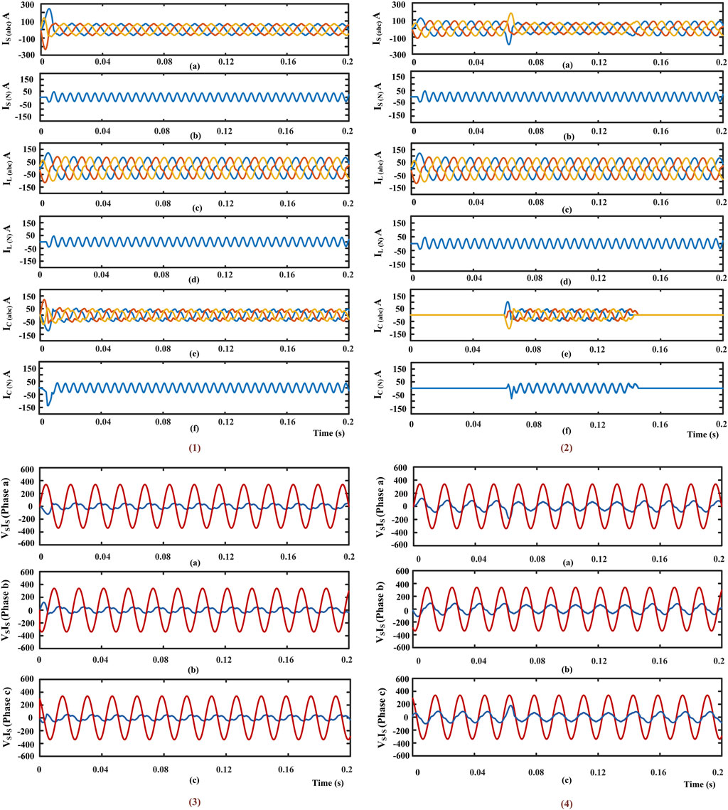
Figure 16. Simulation results.
3.6 HIL experimental set-up results
The RRC is presented in this system to control the PV power fluctuations, and the battery power is obtained based on the difference between Ppv and Pr. The variable PV current and battery current profiles are presented in Figures 17A, B. The BESS in a steady state gives/takes the fraction of deficit/surplus power, and the SC absorbs the transient change in PV and load power. Whenever the battery experiences an abrupt change, the battery current undergoes a significant increase or decrease. If the battery responds to these sudden changes, it will create stress on the battery. Hence, the lifetime of the battery will be reduced. As shown in Figure 17C, the SC eliminates transients from the battery and reduce stress on the battery. The load current required for the variable DC load is shown in Figure 18B. The VDC is shown in Figure 18A. The DC grid voltage remains constant during sudden variations in load. The battery state of charge (SoC) is illustrated in Figure 19.
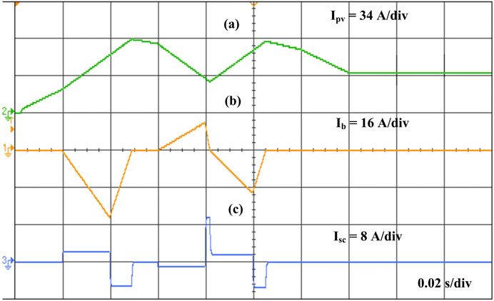
Figure 17. (a) Variable PV current (Ipv), (b) Battery current (Ib), (c) SC current (Isc).
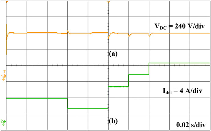
Figure 18. (a) DC bus voltage (VDC), (b) Load current (Idcl).
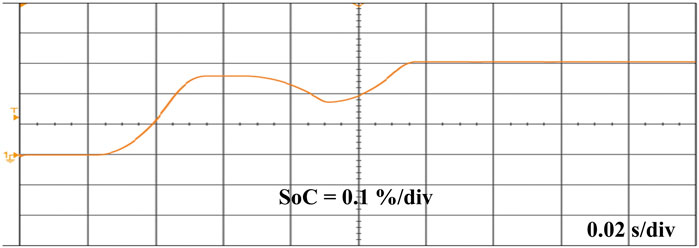
Figure 19. SoC of the battery.
A 3-phase CB is connected to the p-q theory-based controller between the source and the VSI. The shunt APF with a PV array system when a controller is not present, and the CB is disconnected from the source is shown in Figure 20A, B. When the controller is removed from the device, the source current continues to follow the sinusoidal wave pattern. The availability of the neutral wire has led to a reduction in the amplitude of current flowing through the device.
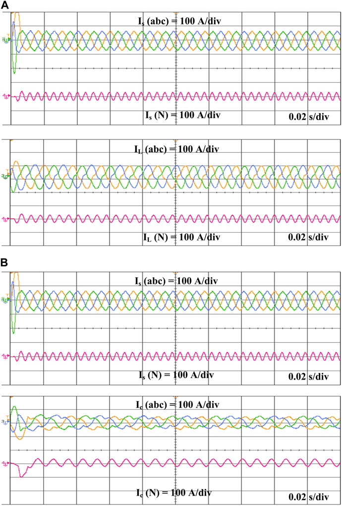
Figure 20. (A) Source IS(abc), load IL(abc) currents, and (B) Source IS(abc) and compensation Ic(abc) currents.
Due to the non-linear nature of the load, harmonics occur between 0.06 and 0.14 s when the CB is closed, and the controller is connected to the device. The compensated current (Ic) produced by the p-q theory-based controller is shown in Figure 21. It injects current into sources that are similar in amplitude but opposite in phase to the reverse harmonics in the p-q theory-based system. It produces compensated currents that nullify the harmonics generated by the current source by comparing the source and load currents. The source current (Isabc) is sinusoidal in Figure 21 for the time interval of 0.06–0.14 s. The AC source (Is), compensation (Ic), and load (IL) currents are depicted in Figure 21. The generated Ic balances the difference measured between the IL and Is associated with the PV system through a CDC. The source voltage (Vs) and current (Is) waveforms without a controller are not sinusoidal due to non-linear load harmonics presented in the system, as shown in Figure 22A. Figure 22B displays the source voltage (Vs) and current (Is) waveforms, which are sinusoidal in nature during the interval from 0.06 to 0.14 s. The harmonic spectra for grid THD with SAPF is 3.28%, as depicted in Figure 23, indicating an enhancement in the performance and power quality of the system. Table 2 compares the THD analysis between the proposed method and existing approaches. The table displays different control strategies outlined in referenced papers, highlighting that the conventional methods utilizing solar PV, APF, and Grid control exhibit higher THD values compared to the proposed approach. In contrast, the proposed method integrates PV and HESS with RRC strategy, along with compensation techniques using APF, resulting in superior outcomes.
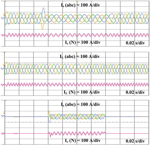
Figure 21. Source IS(abc), load IL(abc), and compensation IC(abc) currents using a p-q based controller.
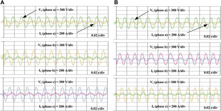
Figure 22. (A) Source voltage (VS(abc)) and current (IS(abc)) waveforms with non-linear load, (B) Source voltage (VS(abc)) and current (IS(abc) waveforms after compensation.
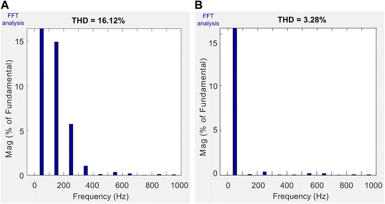
Figure 23. (A) IL (phase-a) harmonics, (B) Ig (phase-a) harmonics.
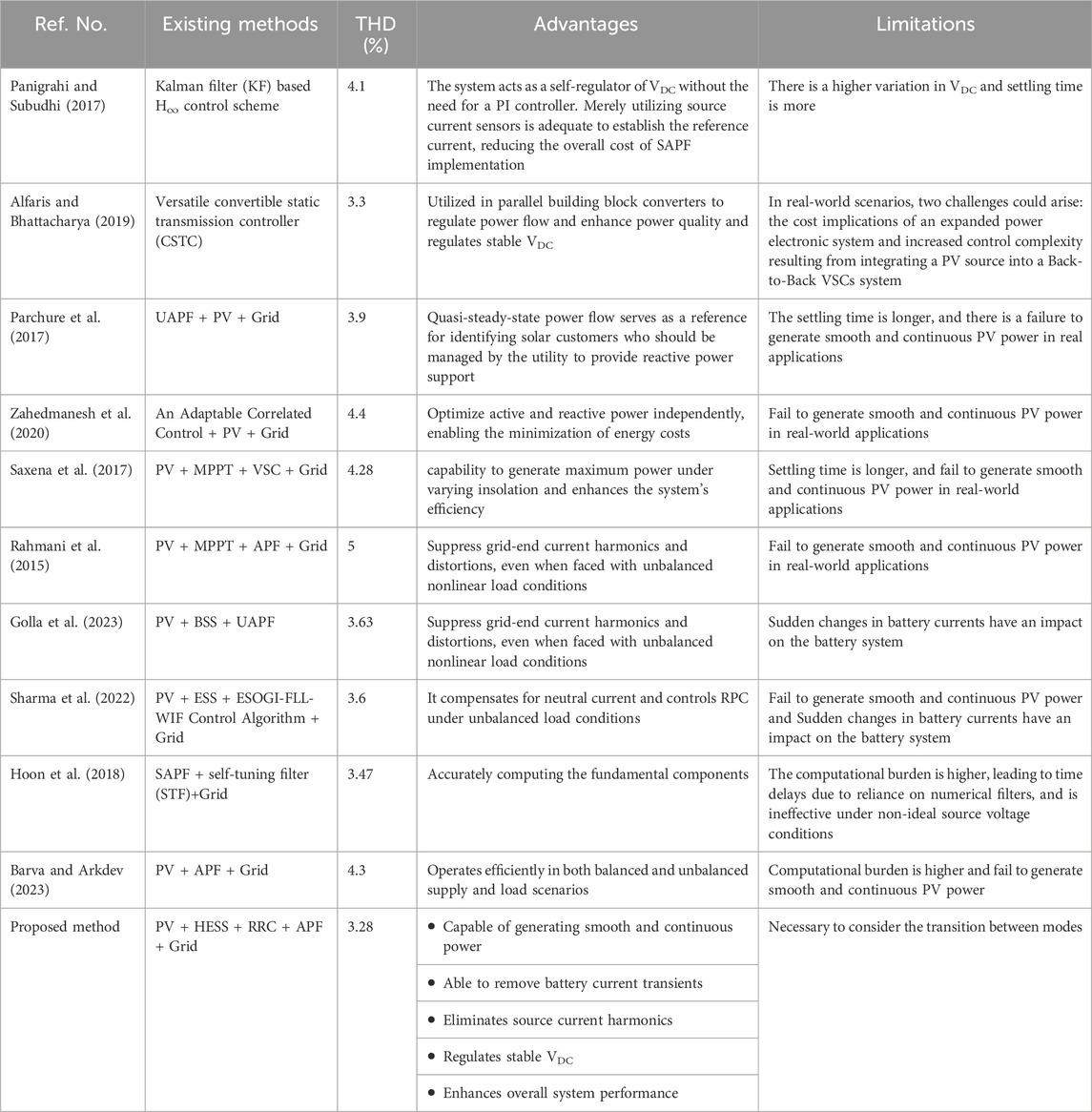
Table 2. A comparison study of THD between the proposed and existing methods.
4 Conclusion
This paper introduces a RRC approach for enhancing the power quality of a PV system integrated with HESS. This method effectively mitigates harmonics and compensates for non-linear reactive power, offering simultaneous control over harmonic currents and RPC. HIL tests demonstrate the filtering of current and voltage waveforms. With the integration of a shunt APF, the grid THD is reduced to 3.28%, showcasing the robust filtering capabilities for harmonic currents and optimal compensation for reactive power. This improvement in power quality aligns with the IEEE-519 standard criterion. The output of the PV system fluctuates depending on the irradiance levels. When the PV power output is low, the battery steps in to provide power, ensuring a steady supply. By doing so, it smooths out fluctuations in PV power and maintains a constant voltage across the DC-link capacitor, resulting in more stable power delivery to the system. However, sudden changes in battery power can put stress on the battery. To address this issue, a SC is employed to eliminate transients from the battery, ensuring smoother operation. This combination of distributed generation with enhanced power quality offers a promising approach for future distribution systems.
5 Future scope
The inherent unpredictability of RESs poses significant technical hurdles in both grid and island-mode operations. Moreover, designing suitable management strategies for ensuring the reliable and uninterrupted operation of the system demands careful attention to the transition between these modes. Therefore, future research will focus on implementing various control techniques and algorithms to enhance power quality in grid-integrated MGs equipped with HESSs. Additionally, the fluctuating output of PV power can be mitigated using advanced smoothing control techniques, which hold promise for large-scale power applications aiming to maintain stability and enhance overall system power quality. Furthermore, the effective implementation of advanced techniques for controlling HESS brings several benefits to renewable energy producers and system operators.
Data availability statement
The original contributions presented in the study are included in the article/supplementary material, further inquiries can be directed to the corresponding author.
Author contributions
GK: Conceptualization, Data curation, Formal Analysis, Methodology, Resources, Software, Validation, Writing–original draft, Writing–review and editing. KP: Investigation, Project administration, Supervision, Validation, Visualization, Writing–review and editing. ED: Funding acquisition, Investigation, Project administration, Supervision, Validation, Visualization, Writing–review and editing.
Funding
The author(s) declare that financial support was received for the research, authorship, and/or publication of this article. This work was supported by the Department of Science and Technology (DST), Government of India (GOI), with project grant SR/FST/ETI-420/2016(C) under the FIST scheme. It was also supported by the European Union Next-Generation EU (National Recovery and Resilience Plan (NRRP), Mission 4 Component 2 Investment 1.3) under the Network 4 Energy Sustainable Transition (NEST) Extended Partnership (Italian Ministry of University and Research Decree No. 1561 of 11/10/2022) under Project PE00000021.
Conflict of interest
The authors declare that the research was conducted in the absence of any commercial or financial relationships that could be construed as a potential conflict of interest.
Publisher’s note
All claims expressed in this article are solely those of the authors and do not necessarily represent those of their affiliated organizations, or those of the publisher, the editors and the reviewers. Any product that may be evaluated in this article, or claim that may be made by its manufacturer, is not guaranteed or endorsed by the publisher.
References
Abdullah, A., Biswal, G. R., Roy, A. K., Ijaz, M., Parveen, S., Murtaza, S., et al. (2016). “Molecular diagnosis and phylogenetic analysis of human papillomavirus type-16 from suspected patients in Pakistan,” in 2016 IEEE 1st International Conference on Intelligent Control and Energy Systems (ICPEICES), Delhi, India, July 4-6, 2016, 1–6.
Alfaris, F. E., and Bhattacharya, S. (2019). Control and real-time validation for convertible static transmission controller enabled dual active power filters and PV integration. IEEE Trans. Ind. Appl. 55 (4), 4309–4320. doi:10.1109/tia.2019.2910782
Barva, A. V., and Arkdev, (2023). “Analysis of SAPF based on p-q and SRF theory for different supply and load conditions,” in 2023 International Conference on Power, Instrumentation, Energy and Control (PIECON), Aligarh, India, 10-12 February 2023, 1–6.
Belaidi, R., Hatti, M., Haddouche, A., and Larafi, M. M. (2013). “Shunt active power filter connected to a photovoltaic array for compensating harmonics and reactive power simultaneously,” in 4th International Conference on Power Engineering, Energy and Electrical Drives, Istanbul, Turkey, 13-17 May 2013, 1482–1486.
Benchouia, M. T., Ghadbane, I., Golea, A., Srairi, K., and Benbouzid, M. E. H. (2015). Implementation of adaptive fuzzy logic and PI controllers to regulate the DC bus voltage of shunt active power filter. Appl. Soft Comput. 28, 125–131. doi:10.1016/j.asoc.2014.10.043
Beniwal, N., Hussain, I., and Singh, B. (2018). Control and operation of a solar PV-battery-grid-tied system in fixed and variable power mode. IET Generation, Transm. Distribution 12 (11), 2633–2641. doi:10.1049/iet-gtd.2017.1095
Brahmendra Kumar, G. V., Kumar, G. A., Eswararao, S., and Gehlot, D. (2018). “Modelling and control of BESS for solar integration for PV ramp rate control,” in 2018 International Conference on Computation of Power, Energy, Information and Communication (ICCPEIC), Chennai, India, 28-29 March 2018, 368–374.
Brahmendra Kumar, G. V., and Palanisamy, K. (2019). A review on microgrids with distributed energy resources. 2019 Innovations Power Adv. Comput. Technol. (i-PACT) 2019, 1–6. doi:10.1109/i-pact44901.2019.8960189
Dashtdar, M., Flah, A., Hosseinimoghadam, S. M., and El-Fergany, A. A. (2022). Frequency control of the islanded microgrid including energy storage using soft computing. Sci. Rep. 12, 20409–20418. doi:10.1038/s41598-022-24758-6
Devassy, S., and Singh, B. (2018). Design and performance analysis of three-phase solar PV integrated UPQC. IEEE Trans. Ind. Appl. 54 (1), 73–81. doi:10.1109/tia.2017.2754983
Devassy, S., and Singh, B. (2019). Implementation of solar photovoltaic system with universal active filtering capability. IEEE Trans. Ind. Appl. 55 (4), 3926–3934. doi:10.1109/tia.2019.2906297
Echalih, S., Abouloifa, A., Lachkar, I., Aroudi, A. E., Hekss, Z., Giri, F., et al. (2022). A cascaded controller for a grid-tied photovoltaic system with three-phase half-bridge interleaved buck shunt active power filter: hybrid control strategy and fuzzy logic approach. IEEE J. Emerg. Sel. Top. Circuits Syst. 12 (1), 320–330. doi:10.1109/jetcas.2022.3152535
Fabricio, E. L. L., Júnior, S. C. S., Jacobina, C. B., and Corrêa, M. B. (2018). Analysis of main topologies of shunt active power filters applied to four-wire systems. IEEE Trans. Power Electron 33, 2100–2112. doi:10.1109/tpel.2017.2698439
Golla, M., Thangavel, S., Simon, S. P., and Padhy, N. P. (2023). An enhancement of power quality with efficient active power transfer capability in a PV–BSS-fed UAPF for microgrid realization. IEEE Syst. J. 17 (1), 1614–1625. doi:10.1109/jsyst.2022.3179182
Gundumalla, V. B. K., and Eswararao, S. (2018). “Ramp rate control strategy for an islanded DC microgrid with hybrid energy storage system,” in 2018 4th International Conference on Electrical Energy Systems (ICEES), Chennai, India, 7-9 February 2018, 82–87.
Hoon, Y., Radzi, M. A. M., Hassan, M. K., and Mailah, N. F. (2018). Operation of three-level inverter-based shunt active power filter under non-ideal grid voltage conditions with dual fundamental component extraction. IEEE Trans. Power Electron 33 (9), 7558–7570. doi:10.1109/tpel.2017.2766268
Jasim, A. M., Jasim, B. H., Flah, A., Bolshev, V., and Mihet-Popa, L. (2023). A new optimized demand management system for smart grid-based residential buildings adopting renewable and storage energies. Energy Rep. 9, 4018–4035. doi:10.1016/j.egyr.2023.03.038
Khan, I., Vijay., A. S., and Doolla, S. (2022). Nonlinear load harmonic mitigation strategies in microgrids: state of the art. IEEE Syst. J. 16 (3), 4243–4255. doi:10.1109/jsyst.2021.3130612
Kumar, G., Sarojini, R., Palanisamy, K., Padmanaban, S., and Holm-Nielsen, J. (2019). Large scale renewable energy integration: issues and solutions. Energies 12 (10), 1996–2017. doi:10.3390/en12101996
Kumar, G. V. B., and Palanisamy, K. (2019). “Interleaved boost converter for renewable energy application with energy storage system,” in 2019 IEEE 1st International Conference on Energy, Systems and Information Processing (ICESIP), Chennai, India, 4-6 July 2019, 1–50.
Kumar, G. V. B., and Palanisamy, K. (2020). A review of energy storage participation for ancillary services in a microgrid environment. Inventions 5 (4), 63–36. doi:10.3390/inventions5040063
Kumar, G. V. B., and Palanisamy, K. (2023). Ramp-rate control for mitigation of solar PV fluctuations with hybrid energy storage system. Distributed Generation Altern. Energy J. 38 (03), 817–840. doi:10.13052/dgaej2156-3306.3835
Kumar, G. V. B., Palanisamy, K., Padmanaban, S., Holm-Nielsen, J. B., and Blaabjerg, F. (2020). Effective management system for solar PV using real-time data with hybrid energy storage system. Appl. Sci. 10 (3), 1–15. doi:10.3390/app10031108
Kumar, G. V. B., Palanisamy, K., and Tuglie, E. D. (2021). “Energy management of PV-Grid-Integrated microgrid with hybrid energy storage system,” in 2021 International Conference on Environment and Electrical Engineering and 2021 IEEE Industrial and Commercial Power Systems Europe (EEEIC/ I&CPS Europe), Bari, Italy, 7-10 September 2021, 1–6.
Kumar, R., and Bansal, H. O. (2019). Hardware in the loop implementation of wavelet-based strategy in shunt active power filter to mitigate power quality issues. Electr. Power Syst. Res. 169, 92–104. doi:10.1016/j.epsr.2019.01.001
Kuznetsov, P., Kotelnikov, D., Yuferev, L., Panchenko, V., Bolshev, V., Jasiński, M., et al. (2022). Method for the automated inspection of the surfaces of photovoltaic modules. Sustainability 14 (19), 11930. doi:10.3390/su141911930
Liang, W., Liu, Y., and Shen, Y. (2023). Active power control integrated with reactive power compensation of battery energy stored quasi-Z source inverter PV power system operating in VSG mode. IEEE J. Emerg. Sel. Top. Power Electron. 11 (1), 339–350. doi:10.1109/jestpe.2021.3137397
Panigrahi, R., and Subudhi, B. (2017). Performance enhancement of shunt active power filter using a kalman filter-based hα control strategy. IEEE Trans. Power Electron. 32 (4), 2622–2630. doi:10.1109/tpel.2016.2572142
Parchure, A., Tyler, S. J., Peskin, M. A., Rahimi, K., Broadwater, R. P., and Dilekm, M. (2017). Investigating PV generation induced voltage volatility for customers sharing a distribution service transformer. IEEE Trans. Ind. Appl. 53 (1), 71–79. doi:10.1109/tia.2016.2610949
Patel, N., Bansal, R. C., Adam, A. A., Elnady, A., and Hamid, A. K. (2023). Multimode control for power quality improvement in an electronically coupled distributed generation unit under grid connected and autonomous modes. IEEE Trans. Power Deliv. 38 (4), 2274–2289. doi:10.1109/tpwrd.2023.3237835
Pradeep Reddy, G., Kumar, Y. V. P., Kalyan Chakravarthi, M., and Flah, A. (2022). Refined network topology for improved reliability and enhanced dijkstra algorithm for optimal path selection during link failures in cluster microgrids. Sustainability 14 (16), 10367. doi:10.3390/su141610367
Rahmani, B., Li, W., and Liu, G. (2015). An advanced universal power quality conditioning system and MPPT method for grid integration of photovoltaic systems. Electr. Power Energy Syst. 69, 76–84. doi:10.1016/j.ijepes.2014.12.031
Rauf, A. M., and Khadkikar, V. (2015). Integrated photovoltaic and dynamic voltage restorer system configuration. IEEE Trans. Sustain Energy 6 (2), 400–410. doi:10.1109/tste.2014.2381291
Ray, P., Ray, P. K., and Dash, S. K. (2022). Power quality enhancement and power flow analysis of a PV integrated UPQC system in a distribution network. IEEE Trans. Ind. Appl. 58 (1), 201–211. doi:10.1109/tia.2021.3131404
Saxena, N., Singh, B., and Vyas, A. L. (2017). Single-phase solar PV system with battery and exchange of power in grid-connected and standalone modes. IET Renew. Power Gen. 11 (2), 325–333. doi:10.1049/iet-rpg.2016.0143
Sharma, R., Kewat, S., and Singh, B. (2022). Power quality improvement in SyRG-PV-BES-based standalone microgrid using ESOGI-FLL-WIF control algorithm. IEEE Trans. Industry Appl. 58 (1), 686–696. doi:10.1109/tia.2021.3128371
Tareen, W. U. K., and Mekhielf, S. (2018). Three-phase transformer less shunt active power filter with reduced switch count for harmonic compensation in grid-connected applications. IEEE Trans. Power Electron 33 (6), 4868–4881. doi:10.1109/tpel.2017.2728602
Wang, C., Yang, T., Hussaini, H., Huang, Z., and Bozhko, S. (2022). Power quality improvement using an active power sharing scheme in more electric aircraft. IEEE Trans. Ind. Electron 69 (4), 3588–3598. doi:10.1109/tie.2021.3076401
Wategaonkar, S. S., Patil, S. S., and Jadhav, P. R. (2018). “Mitigation of current harmonics using shunt active power filter,” in 2018 3rd International Conference for Convergence in Technology (I2CT), Pune, India, 6-8 April 2018, 1–5.
Keywords: PV system, hybrid energy storage system, ramp-rate control, shunt active power filter, harmonics, power quality
Citation: Brahmendra Kumar GV, Palanisamy K and De Tuglie E (2024) Ramp-rate control for power quality improvement of renewable grid-integrated microgrid with hybrid energy storage system. Front. Energy Res. 12:1387908. doi: 10.3389/fenrg.2024.1387908
Received: 18 February 2024; Accepted: 29 April 2024;
Published: 13 June 2024.
Edited by:
Sudhakar Babu Thanikanti, Chaitanya Bharathi Institute of Technology, IndiaReviewed by:
T. Yuvaraj, Chennai Institute of Technology, IndiaAli Q. Al-shetwi, Fahd bin Sultan University, Saudi Arabia
P. Balamurugan, Loyola Institute of Technology, India
Copyright © 2024 Brahmendra Kumar, Palanisamy and De Tuglie. This is an open-access article distributed under the terms of the Creative Commons Attribution License (CC BY). The use, distribution or reproduction in other forums is permitted, provided the original author(s) and the copyright owner(s) are credited and that the original publication in this journal is cited, in accordance with accepted academic practice. No use, distribution or reproduction is permitted which does not comply with these terms.
*Correspondence: Enrico De Tuglie, ZW5yaWNvZWxpby5kZXR1Z2xpZUBwb2xpYmEuaXQ=