 Shi Yan Sun
 Ruili Gao1
 Kang Ren
- 1School of Naval Architecture and Ocean Engineering, Jiangsu University of Science and Technology, Zhenjiang, China
- 2Department of Mechanical Engineering, University College London, London, United Kingdom
Introduction: The study presents an integrated system comprising a central platform and four wave-energy converters, with a focus on investigating their coupled motions induced by ocean waves. The interaction between the buoys and the central platform is achieved through the implementation of spring components. The power take-off system is simulated by incorporating damping coefficients and stiffness into these spring components, enabling a detailed analysis of the energy conversion of such system.
Methods: Numerical simulations based on the continuity equation and the Reynolds-Averaged Navier-Stokes (RANS) equations, coupled with the realizable
Results: Detailed results regarding the effects of wave frequency and the damping coefficient of the power take-off system are presented.
Discussion: The results reveal that while both the platform’s motion and the relative motions between buoys and the platform are suppressed, the absolute motion of buoys varies depending on their respective locations within the system and ocean waves. This variation is deeply influenced by the interaction between incident, reflected and diffracted waves within the system.
1 Introduction
Climate change is prompting governments worldwide to accelerate energy transitions. Oceans, covering 71% of the Earth’s surface, are rich in solar, wind and wave energy. Consequently, developing offshore floating energy harvesting is expected to contribute significantly to net zero. So far, there have been many attempts to generate electricity by floating offshore ocean structures. However, the complex marine environment poses technical challenges to these activities, resulting in high costs and threatening equipment operations. The development of new floating platform solutions for hybrid renewable energy harvesting is expected to help reduce costs and improve safety.
An example of ocean-floating hybrid clean energy platform is developed by SINN Power. This innovative platform integrates various renewable energy sources, including solar, wind, and wave energy. Photovoltaic panels and small wind turbines are securely fixed to the truss structure of the floating platform. While prototype of hybrid power system is still scarce, extensive theoretical studies and experimental endeavours have been conducted. Sun et al. (2021) delved into the exploration of an array of heaving buoys encircling an A-shaped platform, employing both numerical simulations and experimental methods. They derived an optimization model by fine-tuning the spacing and arrangement of the buoys. Zheng and Zhang (2020) scrutinized the power performance, as well as the motion and pressure responses of a hybrid wave farm, incorporating oscillating water columns and point absorbers, utilizing a semi-analytical model. Their findings provided insights into the mooring type of oscillating water column (OWC), wave conditions, and the overall configuration of the farm. Cheng et al. (2022a) introduced a hybrid semi-submersible floating platform integrated with a flap-type wave energy converter and two oscillating buoys. Cheng et al. (2022b) proposed a novel concept: a hybrid wave energy conversion (WEC) and breakwater system combining an OWC and an oscillating buoy. Both experimental work and numerical simulations were conducted, and the results indicated a preference for the hybrid WEC concept, not only due to higher energy conversion but also for more robust wave attenuation. Further endeavours in this line of thought, including the combination of breakwater, oscillating buoy, and OWC, are being pursued by Lei et al. (2022), Cheng et al. (2022c) and Cheng et al. (2024). Cui et al. (2021) suggested a hybrid design featuring a cylindrical half-opening oscillating water column and a hinged oscillating buoy. Their research demonstrated that the hybrid system generally outperforms single OWC or single oscillating buoy in both frequency bandwidth and incident wave angle band. Nguyen and Wang (2020) utilized a linear power take-off system to connect a pontoon-type very large floating structure (VLFS) to the seabed. The wave energy is absorbed by the power take-off system through the motion of VLFS, achieving both wave energy extraction and a reduction in the hydroelastic response of the VLFS. Additionally, various studies explore energy extraction from the motion of VLFS, such as those by Nguyen et al. (2019) using a raft attachment, and Zhang et al. (2019) and Ren et al. (2019) by installing PTO systems between VLFS modules for extracting wave energy. Zhou et al. (2023a) contemplated a hybrid system involving a heaving cylindrical wave energy converter positioned in front of a parabolic breakwater. Furthermore, Zhou et al. (2023b) and Jin et al. (2023) delved into the wind-wave hybrid system, incorporating a floating offshore wind turbine alongside wave energy converters.
Numerical and experimental investigations into hybrid systems comprising platforms and wave energy converters are flourishing. However, the coupling between these components is not fully addressed in numerical analysis. Many studies focus on the coupling effect through hydrodynamic forces, accounting for the effects of both the motion of converters and the platforms. However, the power take-off system is typically applied solely to the wave energy converters, neglecting its direct impact on the platform. In offshore engineering, these components are interconnected rather than isolated. In the current work, we address this by incorporating spring components to establish a connection between the platform and oscillating buoys. The PTO system is simulated by introducing damping coefficients and stiffness to the springs. This approach allows the interaction force between the platform and oscillating buoys to be transmitted through the springs, with power being extracted accordingly. The spring force, in turn, depends on the relative motion between the platform and the spring. This nuanced understanding of coupling dynamics provides a more comprehensive insight into the interaction between platforms and wave energy converters in offshore engineering applications.
2 Analysis of energy harvesting system
2.1 Configuration
Figure 1 illustrates a comprehensive floating energy system, featuring a floating semi-submersible platform with a concave wall, where the top surface can be mounted with solar photovoltaic panels, in addition to four spherical oscillating buoys around it. Each heaving buoy is linked to the central platform through two spring components, allowing for the utilization of suitable power take-off mechanisms to extract energy and convert it into electricity. The floating platform and heaving buoys are motivated by ocean waves, with their mutual dependence realized through the springs connecting them. In this study, we focus solely on analysing the heaving motions of the platform and four buoys, as well as their coupling effects through the spring components.
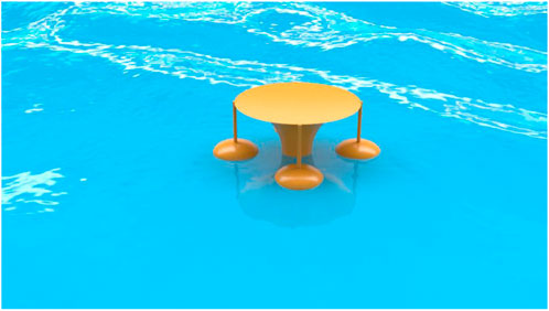
Figure 1. Visualization of the integrated energy system in the ocean.
To better describe the integrated system, a Cartesian coordinate system is established with the origin O at the mass centre of the platform, also coinciding with the undisturbed water surface. The x-axis is along the direction of wave propagation, while the y-axis is perpendicular to it. The z-axis points upwards. The semi-submersible platform is featured as a solid of revolution with a concave wall. The illustration of the generatrix for the central platform is displayed in Figure 2. It has a radius
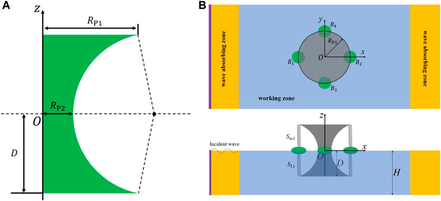
Figure 2. The illustration of (A) the generatrix for the central platform and (B) the top view and side view of the integrated system.
Four spheroid buoys with same geometry, denoted as
2.2 Motion and energy extraction of the system
The motions of the heaving buoys
where
where
where
where
We further assume that the motion becomes sinusoidal with time with frequency
Here,
Due to the coupling of the motion of buoys and the platform, directly determining the optimal damping coefficients of the springs is challenging. However, these coefficients are crucial for identifying the most effective operational state of the comprehensive system. To address this, we simplify the scenario by using a system comprising one buoy and a spring pair to estimate the optimal damping coefficients for the spring components. In this simplified set-up, the upper and lower ends of the springs, initially connected to the platform, are assumed to be fixed in space. Meanwhile, we allow the single buoy with two springs to move in response to waves. This leads to
where
in which
From (8), the natural frequency
Therefore, the mechanical energy
where
3 Numerical model
To obtain the values of hydrodynamic variables mentioned in Section 2.2, the interaction between ocean waves and the comprehensive floating energy harvesting system is examined in the numerical tank. The continuity equation and RANS equations for an incompressible Newtonian fluid can be expressed in the Einstein notation in Cartesian coordinate system as follows
where t is time, ρ is the density of the fluid,
The use of Eq. 14 can transform the equation of
As displayed in Figure 2B, the numerical tank is divided into two kinds of zones: the working zone and the wave-absorbing zone. Boundary conditions in the 3D computational domain are configured as follows: the left-hand side boundary is specified as a velocity inlet, generating the fifth-order Stokes incident waves. The right-hand side boundary is set as a pressure outlet. Tank lateral surfaces are designated as symmetry boundaries, and the bottom is modelled as a wall boundary. On the domain’s top, a velocity inlet boundary condition is used. To mitigate reflected and diffracted waves propagating to the inlet and outlet, a forcing method is employed in wave-absorbing zone.
4 Results and analysis
4.1 The shape of heaving buoy
To select the appropriate geometric shape for the buoy, we may utilize Eqs. 10 and (11) for an approximate estimation. In these equations, the hydrodynamic coefficients such as the added mass
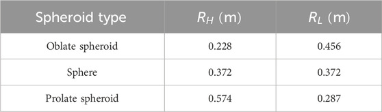
Table 1. Spheroid types with different parameters.
They have the same mass, which is
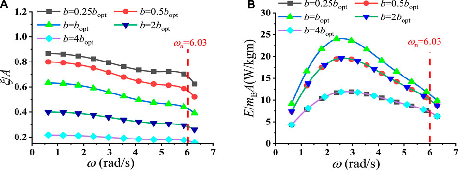
Figure 3. Frequency-domain analysis for an oblate spheroid: (A) motion amplitude per wave amplitude and (B) absorbed energy per second per body mass per wave amplitude.
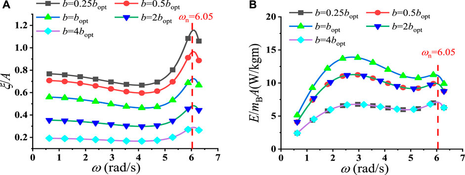
Figure 4. Frequency-domain analysis for a sphere: (A) motion amplitude per wave amplitude and (B) absorbed energy per second per mass per wave amplitude.
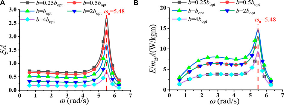
Figure 5. Frequency-domain analysis for a prolate spheroid: (A) motion amplitude per wave amplitude and (B) absorbed energy per second per mass per wave amplitude.
We may investigate these curves further. According to Eq. 8, it can be observed that if the term
For the oblate spheroid case, as the damping force of spring is noticeably important than other force components, the energy peak mainly depends on the peak of
4.2 Nonlinear numerical setup and convergence study
The time-domain simulation of wave interaction with the integrated system is conducted. Four oblate spheroid buoys with identical geometries, as outlined in Table 1, along with a floating platform with dimensions
The convergence study is conducted based on a case study where the circular radian frequency
Trimmed meshes are used to discretize the entire computational domain. To account for the motion of bodies, an overset mesh approach is employed. Within the overset domain, the finer mesh relative to the body size is utilized. To enhance numerical efficiency, a multi-block grid has been used. Finer meshes are adopted to regions within the overset domain and in close proximity to the free surface. For example, the region close to the free surface is encrypted four times in z direction. The remaining domain is divided into four subdomains, as illustrated in Figure 6. Mesh sizes within subdomain 1, 2, 3 and 4 are established as
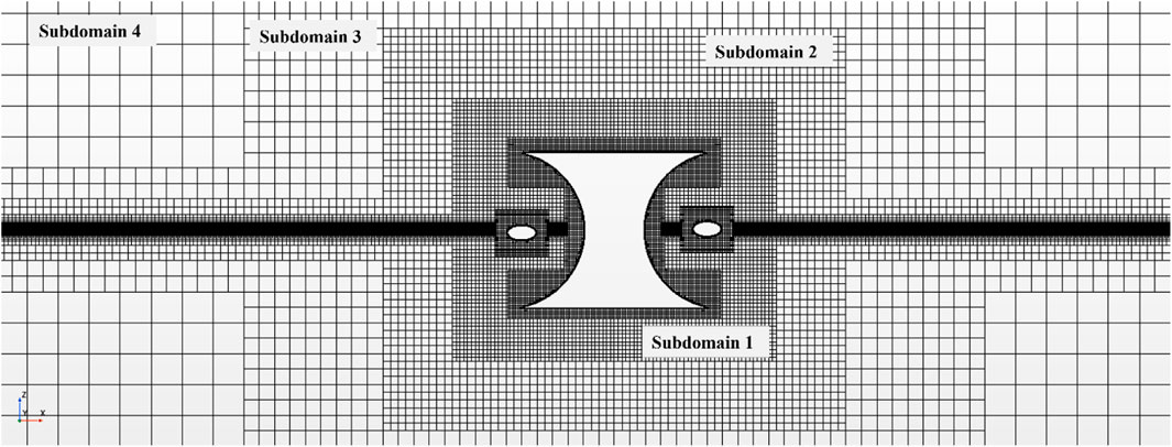
Figure 6. Trimmed mesh for the computational domain.
In addition, time step (dt) is set at 0.005s and 0.0025s, respectively. Figure 7 presents the studies of the mesh convergence and time step convergence for the vertical motion of platform in the integrated system, while Figure 8 depicts those for buoy 1. Similar convergence results are observed for Buoys 2 to 4 and hence only the results of buoy 1 are provided. The good agreement seen in Figure 7 and 8 verifies that the present procedure is dependent of both time and mesh. Subsequently, simulations were conducted using
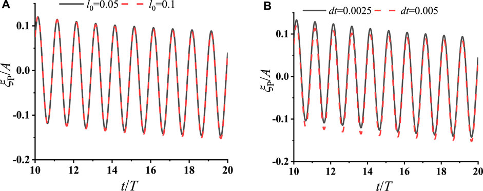
Figure 7. Convergence study for the motion amplitude of the central platform with respect to (A) mesh and (B) time step.
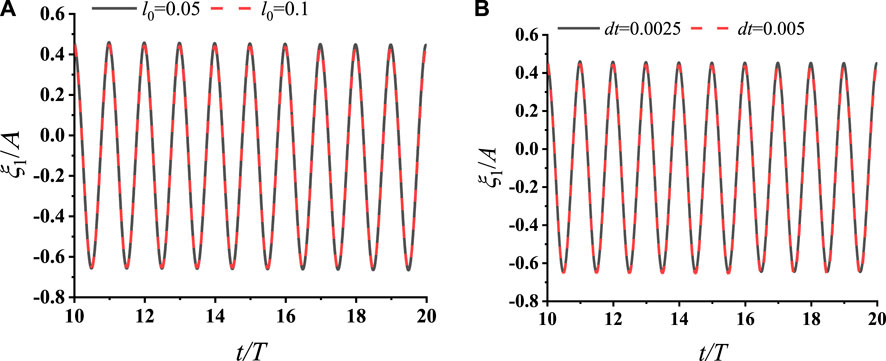
Figure 8. Convergence study for the motion amplitude of the buoy
4.3 The effect of incident wave frequencies
In this section, we explore the impact of incident wave frequencies. The parameters of the buoys and the central platform remain consistent with those utilized in the convergency study, despite being subjected to varying wave frequencies. Specifically, six wave frequencies are selected as 0.628
The optimal damping coefficient,
Figure 9A illustrates a comparison of the prediction of the motion amplitudes between a single platform analysed in the frequency domain using linearized potential flow theory and the platform coupled with springs and buoys in the integrated system, as analysed in the time domain simulation based on Reynolds-Averaged Navier-Stokes (RANS) equations. The latter one is obtained through a long-time simulation to achieve its steady state. It is observed that the motion amplitudes of platform in the integrated system are generally smaller than those of a single platform in the frequency-domain simulation. This discrepancy may be attributed to several factors. First, the inclusion of buoys alters the mass of the entire system, along with added mass and wave-exciting forces. In addition, a portion of the wave energy is absorbed by the wave energy converters surrounding the platform, leading to a reduction in platform motion. As the wave frequency increases, the motion amplitudes for both cases gradually diminish. It is expected that as the wavelength becomes very short, numerous wave elements will surround the bodies, potentially resulting in the cancellation of the hydrodynamic effects.
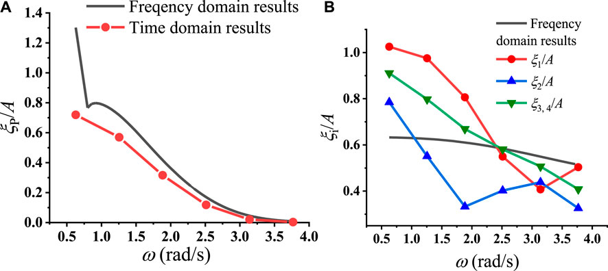
Figure 9. (A) The motion of platform and (B) absolute motion amplitudes
In addition to the central platform, Figure 9B illustrates the motion amplitudes of the four buoys in the coupled system, along with the motion amplitude of the single buoy in frequency domain based on linearized analysis. As the symmetry of the positions of
This observation appears to contradict the intuition that the motion amplitude of buoy
From the previous analysis and Eq. 5, it becomes evident that the relative motion between the platform and buoy
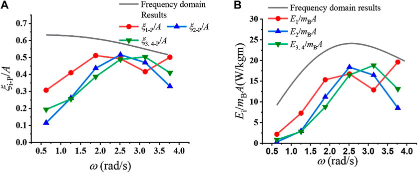
Figure 10. (A) Relative motion of buoys and (B) absorbed energy of the combined system at different wave frequencies.
At
4.4 The effect of damping coefficient
Figure 11 presents the results obtained with different damping coefficients. Specifically,
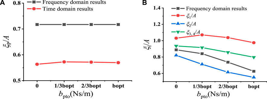
Figure 11. (A) The motion of platform and (B) absolute motion amplitudes
Figure 11A illustrates the motion of the platform in the frequency-domain analysis without buoys and the time-domain analysis integrated system coupled with buoys, with the latter exhibiting smaller motion response compared to the former. One reason for this discrepancy is the absorption of wave energy by the surrounding buoys, while another factor is the alteration of the system’s dynamic performance due to the increased mass, added mass etc. However, it is noteworthy that the variation in platform motion with changes in the springs’ damping coefficient is not significant. Therefore, we can conclude that the variation in the dynamic performance of the system exerts more profound effects on the motion of the platform. Figure 11B displays the absolute motion amplitudes of the buoys, and the frequency-domain prediction of a single buoy is also displayed for comparison. Among the buoys,
The relative motion results are illustrated in Figure 12A, with
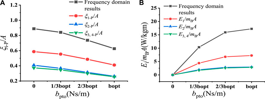
Figure 12. (A) Relative motion of buoys and (B) absorbed energy of the combined system at different damping coefficients
5 Conclusion
A coupled energy harvesting system including the central platform, oscillating buoys and spring components are proposed in present work. Specifically, the power take-off system is simulated by introducing damping coefficients and elastic coefficients to the spring components. The Reynolds-Averaged Navier-Stokes (RANS) equation and realizable
(1) The motion of the platform in the coupled system is lower than that of a single platform. It can be explained that the addition of buoys alters the dynamic performance of the system, such as increasing mass, added mass and wave exciting force. Additionally, a portion of wave energy would be absorbed by the buoys surrounding the platform.
(2) The variation in platform motion across different damping coefficients in the coupled system is not significant. This implies that the changes in the dynamic performance of the system have a more noticeable effect on the motion of platform than the energy absorption of buoys.
(3) The absolute motion of buoys is primarily influenced by the interaction of incident, reflected and diffracted waves, when the incident wave and reflected wave are cancelled at the front of the platform, the motion amplitude of buoy at this location will drop, while when most of waves are diffracted around the platform, the buoys at two sides and the back will undertake larger motions.
(4) In the couple system, the relative motions between buoys are closer than absolute motions. The absorbed energy, which is directly related to the relative motion, also shows a similar variation trend.
Data availability statement
The original contributions presented in the study are included in the article/supplementary material, further inquiries can be directed to the corresponding author.
Author contributions
SS: Writing–original draft, Writing–review and editing, Funding acquisition. RG: Writing–original draft. YL: Writing–review and editing. KR: Writing–original draft, Writing–review and editing.
Funding
The author(s) declare that financial support was received for the research, authorship, and/or publication of this article. This work is supported by the Royal Society (Grant No. IEC\NSFC\223358) and the National Natural Science Foundation of China (Grant No. 52271276).
Conflict of interest
The authors declare that the research was conducted in the absence of any commercial or financial relationships that could be construed as a potential conflict of interest.
Publisher’s note
All claims expressed in this article are solely those of the authors and do not necessarily represent those of their affiliated organizations, or those of the publisher, the editors and the reviewers. Any product that may be evaluated in this article, or claim that may be made by its manufacturer, is not guaranteed or endorsed by the publisher.
References
Cheng, Y., Dai, S. Q., Dai, S. S., Ji, C. Y., Collu, M., Yuan, Z. M., et al. (2022a). Energy conversion and hydrodynamic analysis of multi-degree-of-freedom wave energy converters integrated into a semi-submersible platform. Energy Convers. Manag. 252, 115075. doi:10.1016/j.enconman.2021.115075
Cheng, Y., Fu, L., Dai, S. S., Collu, M., Cui, L., Yuan, Z. M., et al. (2022b). Experimental and numerical analysis of a hybrid WEC-breakwater system combining an oscillating water column and an oscillating buoy. Renew. Sustain. Energy Rev. 169, 112909. doi:10.1016/j.rser.2022.112909
Cheng, Y., Fu, L., Dai, S. S., Collu, M., Ji, C. Y., Yuan, Z. M., et al. (2022c). Experimental and numerical investigation of WEC-type floating breakwaters: a single-pontoon oscillating buoy and a dual-pontoon oscillating water column. Coast. Eng. 177, 104188. doi:10.1016/j.coastaleng.2022.104188
Cheng, Y., Song, F. K., Fu, L., Dai, S. S., Yuan, Z. M., and Incecik, A. (2024). Experimental investigation of a dual-pontoon WEC-type breakwater with a hydraulic-pneumatic complementary power take-off system. Energy 286, 129427. doi:10.1016/j.energy.2023.129427
Cui, L., Zheng, S. M., Zhang, Y. L., Miles, J., and Iglesias, G. (2021). Wave power extraction from a hybrid oscillating water column-oscillating buoy wave energy converter. Renew. Sustain Energy Rev. 135, 110234. doi:10.1016/j.rser.2020.110234
Jin, P., Zheng, Z., Zhou, M., Zhou, B. Z., Wang, L., Yang, Y., et al. (2023). Optimization and evaluation of a semi-submersible wind turbine and oscillating body wave energy converters hybrid system. Energy 282, 128889. doi:10.1016/j.energy.2023.128889
Lei, F., and Cheng, Y. (2022). Hydrodynamic performance of A dual-floater integrated system combining hybrid WECs and floating breakwaters. China Ocean. Eng. 36, 969–979. doi:10.1007/s13344-022-0085-9
Nguyen, H. P., and Wang, C. M. (2020). Heaving wave energy converter-type attachments to a pontoon-type very large floating structure. Eng. Struct. 219, 110964. doi:10.1016/j.engstruct.2020.110964
Nguyen, H. P., Wang, C. M., Flocard, F., and Pedroso, D. M. (2019). Extracting energy while reducing hydroelastic responses of VLFS using a modular raft wec-type attachment. Appl. Ocean Res. 84, 302–316. doi:10.1016/j.apor.2018.11.016
Ren, N. X., Zhang, C., Magee, A. R., Hellan, Ø., Dai, J., and Ang, K. K. (2019). Hydrodynamic analysis of a modular multi-purpose floating structure system with different outermost connector types. Ocean. Eng. 176, 158–168. doi:10.1016/j.oceaneng.2019.02.052
Shih, T. H., Liou, W. W., Shabbir, A., Yang, Z., and Zhu, J. (1995a). A new k-ϵ eddy viscosity model for high Reynolds number turbulent flows. Comput. Fluids 24 (3), 227–238. doi:10.1016/0045-7930(94)00032-t
Shih, T. H., Zhu, J., and John, L., (1995b). A new Reynolds stress algebraic equation model. Comput. Methods Appl. Mech. Eng. 125, 287–302. doi:10.1016/0045-7825(95)00796-4
Sun, P. Y., Hu, S., He, H. Z., Zheng, S. G., Chen, H., Yang, S. H., et al. (2021). Structural optimization on the oscillating-array-buoys for energy-capturing enhancement of a novel floating wave energy converter system. Energy Convers. Manag. 228, 113693. doi:10.1016/j.enconman.2020.113693
Zhang, X. T., Zheng, S. M., Lu, D., and Tian, X. L. (2019). Numerical investigation of the dynamic response and power capture performance of a VLFS with a wave energy conversion unit. Eng. Struct. 195, 62–83. doi:10.1016/j.engstruct.2019.05.077
Zheng, S. M., Zhang, Y. L., and Iglesias, G. (2020). Power capture performance of hybrid wave farms combining different wave energy conversion technologies: the H-factor. Energy 204, 117920. doi:10.1016/j.energy.2020.117920
Zhou, B. Z., Wang, Y., Zheng, Z., Jin, P., and Ning, D. Z. (2023a). Power generation and wave attenuation of a hybrid system involving a heaving cylindrical wave energy converter in front of a parabolic breakwater. Energy 282, 128364. doi:10.1016/j.energy.2023.128364
Keywords: wave energy converter, coupled motion, PLATFORM, combined system, energy conversion
Citation: Sun SY, Gao R, Li Y and Ren K (2024) Hydrodynamic analysis of a floating platform integrated with buoys and spring components for energy conversion. Front. Energy Res. 12:1399784. doi: 10.3389/fenrg.2024.1399784
Received: 12 March 2024; Accepted: 02 April 2024;
Published: 18 April 2024.
Edited by:
Yuquan Zhang, Hohai University, ChinaReviewed by:
Chongwei Zhang, Dalian University of Technology, ChinaShuangrui Yu, University of Strathclyde, United Kingdom
Copyright © 2024 Sun, Gao, Li and Ren. This is an open-access article distributed under the terms of the Creative Commons Attribution License (CC BY). The use, distribution or reproduction in other forums is permitted, provided the original author(s) and the copyright owner(s) are credited and that the original publication in this journal is cited, in accordance with accepted academic practice. No use, distribution or reproduction is permitted which does not comply with these terms.
*Correspondence: Kang Ren, ay5yZW5AdWNsLmFjLnVr