Abstract
Existing feeder block division methods fail to consider the complementary characteristics and uncertainty between power sources and loads, which result in excessive feeder blocks, low inter-block balance, and significant disparity in net load peak-valley difference. To address these issues, a medium-voltage feeder block division method that considers the uncertainty and complementary characteristics of sources and loads is proposed. Firstly, based on the probability density characteristics of sources and loads, an uncertainty model of DG output and load demand is established. Secondly, considering the constraints of block maximum load rate and feeder non-crossing, a feeder block division model is established. Additionally, a set of center circles is defined, and based on this, an improved K-means clustering algorithm is proposed. The initial clustering centers based on the center circles is set, and the clustering centers based on the arcs of the center circles corrected. And the weighted distances between power sources and clustering centers are calculated. An algorithm flow for improved K-means clustering feeder block division is designed accordingly. Finally, the case studies show that the result of block division is improved.
1 Introduction
In recent years, with the shifting towards clean and low-carbon energy consumption (Baoan et al., 2022), the large-scale integration of distributed generations (DGs) into distribution networks has significantly impacted on the network planning (Jun et al., 2020; Li et al., 2020). In practical engineering applications, distribution network planning involves various stages, such as feeder block division, trunk feeder planning, branch line planning, and tie switch allocation. As the primary stage of network planning, feeder block division refers to dividing service areas of substations into multiple feeder blocks. And the network planning will be influenced by feeder block division.
Various feeder block division methods have been proposed. In reference (Zhang et al., 2019), based on candidate corridors of trunk feeder, a global optimization model for distribution network and its corresponding heuristic method are proposed for medium-voltage network planning. As a result, power system planners are able to obtain consistent feeder block division schemes. However, the applicability of this model is limited by the prerequisite of feeders’ candidate corridors. Based on spatial clustering algorithms, a mathematical model for grid optimization division is proposed in reference (Chen et al., 2017). Nevertheless, the decision variables of this model are coordinates of clustering center and distribution transformers within the grid. Based on optimized grid division, a medium-voltage distribution network planning approach is proposed in reference (Xu et al., 2018). To achieve optimal grid division on a global scope, a clustering method for selecting nearby backup substations is proposed. However, this method relies excessively on generic technical principles and the expertise of planner, leading to high variability in results and difficulty in meeting technical and economic rationality. In reference (Shaoyun et al., 2020), considering the complementary characteristics of load time-series, a feeder block division method is proposed. And the evaluation criteria for block division schemes is set. The fundamental idea of the model is to cluster loads that would improve block time-series characteristics. However, the effects of load demand uncertainty and DG integration are not considered. Moreover, rotational centerline distance-weighted alternate positioning algorithm is proposed, and N centerlines are radiated from substations and the weighted distances of all loads to these centerlines are computed. Based on the principle of proximity, loads are clustered. Finally, an optimal feeder block division scheme is obtained. However, the method still has shortcoming. Due to using lines as block clustering centers, the centerlines are set too dense near substations. The marginal effect of weighted factors is poor when computing the weighted distance of loads near substations, thereby reducing the optimization space for feeder block division schemes.
Based on the above analysis, there are still two aspects remain to be further improved. On the one hand, the complementary characteristics of sources and loads can be considered in the division model. When sources and loads with complementary time-series characteristics are allocated to the same feeder block, the result of feeder block division can be improved. On the other hand, the existing research on feeder block division algorithms that use lines as clustering centers. The loads cannot be divided efficiently near substations.
To address these issues, a medium-voltage feeder block division method is proposed that considers the uncertainty and complementary characteristics of sources and loads. The main contributions are as follows.
1) The uncertainty model of distributed generation and loads is established. And a feeder block division model is established with the objectives of block equilibrium rate and peak-valley difference rate. The maximum load rate of feeder blocks is set as a chance constraint, and the feeder non-crossing is set as a rigid constraint.
2) A feeder block division algorithm based on improvement K-means clustering is proposed. Combined with the setting of the center circle, the division of loads and DGs near the substation is more reasonable by using this method.
2 The uncertainty model of DG output and load demand
2.1 The uncertainty model of DG output
Due to the variability of natural conditions, the output of DG is uncertain. It is difficult to analyze their output characteristics directly. Hence, it is necessary to establish a model to describe the uncertainty in DG output. Statistical analysis of extensive historical data reveals that the output follows a Gaussian distribution (Wang et al., 2018; Lu et al., 2020). The probability density of the output of DG can be expressed as Equation 1.
In the equation, represents the output of the DG. denotes the mean output of the DG. stands for the standard deviation of the DG output.
2.2 The uncertainty model of load demand
The electrical load demand in the distribution network is influenced by time, weather, and user behaviour, exhibiting strong randomness and fluctuations. The probability density characteristics of load demand is represented by Gaussian distribution. The probability density of load demand is as Equation 2.
In the equation, represents the load demand value. represents the mean of the load demand. represents the standard deviation.
3 Feeder block division model
3.1 Objective function
In general, each feeder block is independently powered by a feeder. Since the feeders are of the same type and capacity, it is desired that the maximum net load power between blocks is close. Additionally, to alleviate the pressure during high-load supply moments, it is also desired that the peak-valley difference of the net load within feeder blocks is small (Wang and Ting, 2012; Zhang et al., 2020). Therefore, the objective function of this model is represented as Eq. 3:
In the equation, and represent the weights of the two indices. and represent the indices of block balance rate and block peak-valley difference rate, as described in Eqs 4, 5:
In the equation, and represent the maximum and minimum net load power of feeder block , respectively. represents the average of the maximum net load power of all feeder blocks, as described in Eq. 6.
In the equation, represents the number of feeder blocks. As the formula indicates, if the maximum power of each block is more balanced, will be larger. Similarly, if the temporal peak-valley difference within each block j is smaller, the value of will be larger.
The objective function of feeder block division model is obtained by summing up the two indicators with certain weights. and represent the weights of the two indicators, and the sum of the weights is 1. The specific values of the weights are determined based on the importance of different indicators in different power grid regions.
3.2 Constraints
3.2.1 Maximum load rate chance constraint
The N-1 security constraint requires that the maximum load rate of each feeder (corresponding to a feeder block) in the distribution network be less than the upper limit of the load rate. However, due to the uncertainty of DG outputs, the maximum load rate constraint is no longer a deterministic constraint. Therefore, the maximum load rate of feeder blocks is selected as an chance constraint. Unlike conventional constraints, chance constraints allow for the possibility of violation, but the probability of the constraint being satisfied should not be less than the given confidence level (Shaoyun et al., 2011; Han et al., 2017).
Meanwhile, whether the feeder block satisfies the load rate constraint is directly determined by the net load value. It can be obtained by calculating the difference between the total loads and DGs output within the block. Since the probability density functions of DG output and load demand are known, the probability distribution function of the feeder block’s net load value can be calculated as follows:
In the Equations 7–9, represents the net load demand of block . is the mean value of the net load demand. is the standard deviation. and represent the load belonging to feeder block and the numbered set of DG, respectively. and represent the mean and variance of load demand in the load set, respectively. and represent the mean and variance of the output of DGk in the DG set, respectively.
Assuming that the average value of the net load demand carried by feeder block in the period is the largest, the constraint of the maximum load rate of the block should be based on the standard of the period. And is the net load value carried by feeder block in the period, then the constraint of the maximum load rate of the block should meet:
In the equation, is the confidence level. is the maximum load rate. The maximum load rate is related to the connection mode. Taking the single-tie-line mode as an example, the maximum load rate of a single feeder is limited to 50%.
3.2.2 Constraint of feeder non-crossing
The service area of each feeder block cannot overlap.
4 Feeder block division algorithm
4.1 Improved K-means algorithm
The aim of substation service area determination is spatial division centered around several points (substations), forming regions that are approximately circular in shape (Li et al., 2015; Xingquan et al., 2016). Feeder block division further divides the service area of substations, forming regions centered around feeders. Therefore, feeder blocks present a fan-shaped region, which better conforms to the requirements of engineering practice.
Based on the analysis above, some researchers employ traditional K-means clustering algorithm in block division. Firstly, the traditional K-means algorithm performs clustering based on Euclidean distances. However, in practical scenarios, the output of DG and load demand are different, which can lead to unbalanced load distribution among blocks and inability to achieve source-load complementarity. Secondly, the K-means clustering algorithm is an iterative algorithm. And the optimal clustering results are determined by continuously iterating the positions of cluster centers. However, in practical engineering, it is required that feeder blocks are fan-shaped regions centered around substations. Without constraints on the iterative positions of cluster centers, the final clustering results may not meet practical requirements. Therefore, to address the aforementioned engineering practical issues and achieve source-load complementarity, several improvements of the traditional K-means algorithm are proposed (Sadeghian et al., 2020). Firstly, the concept of center circle set is defined, aimed at constraining the positions of cluster centers in each iteration. A detailed description of the definition of the center circle set is as follow.
Center Circle Set Ω: The set of all center circles, where each center circle is a ring centered on the substation. The positions of all center circles are constrained within an annular-shaped region. The width of the annular-shaped region is set as the difference between the maximum supply radius Rmax and the minimum supply radius Rmin. And Rmax and Rmin represent the farthest and nearest Euclidean distances from the loads to the substation, respectively. A polar coordinate system is established with the substation location as the origin. The radius of the center circle ring in the annular-shaped region is the average polar radius of all loads and DGs within the service area of substation. The schematic diagram is shown as Figure 1.
FIGURE 1
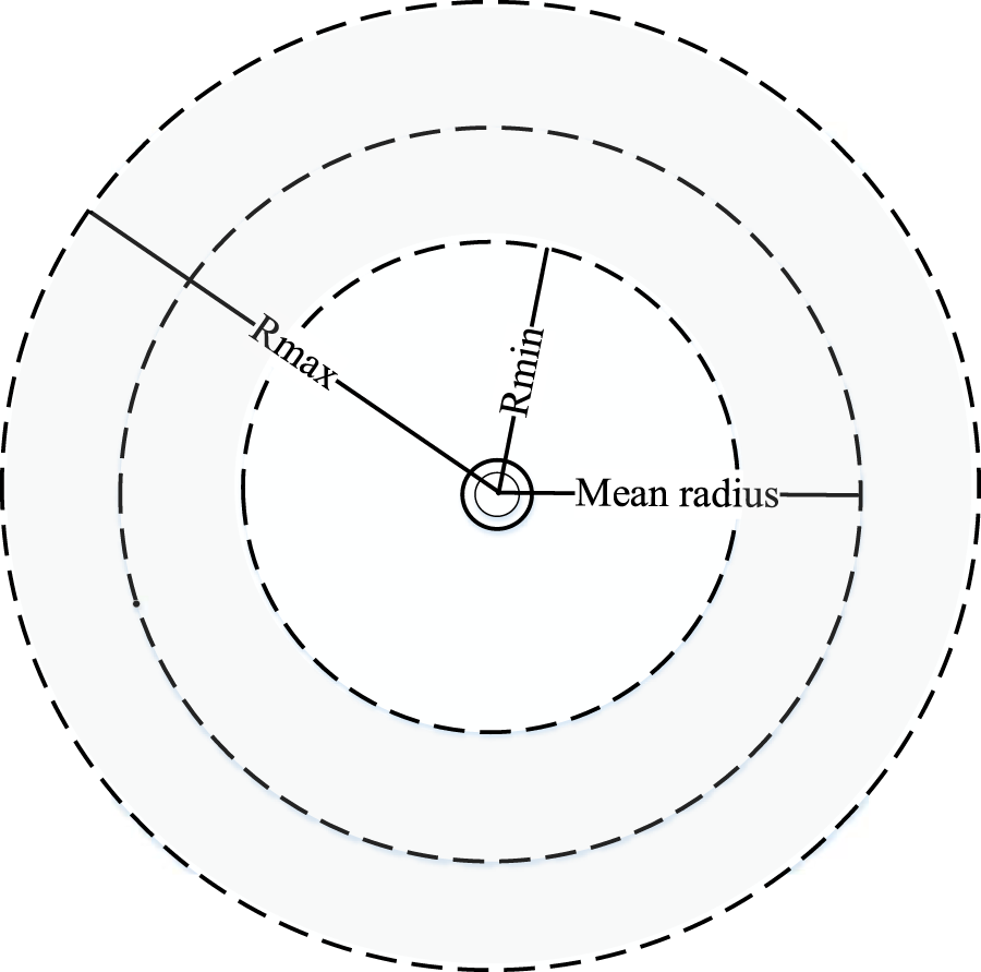
Schematic diagram of the center circle set.
According to the definition of the center circle set mentioned above, the following three improvements to the traditional K-means clustering algorithm is proposed.
4.1.1 Initialization of cluster centers based on the center circle set
The initial cluster centers of each block are evenly distributed along the center circle at intervals of . By sequentially rotating clockwise around the center of the substation by an angle of , different sets of initial cluster centers can be obtained. The schematic diagram is shown as Figure 2.
FIGURE 2
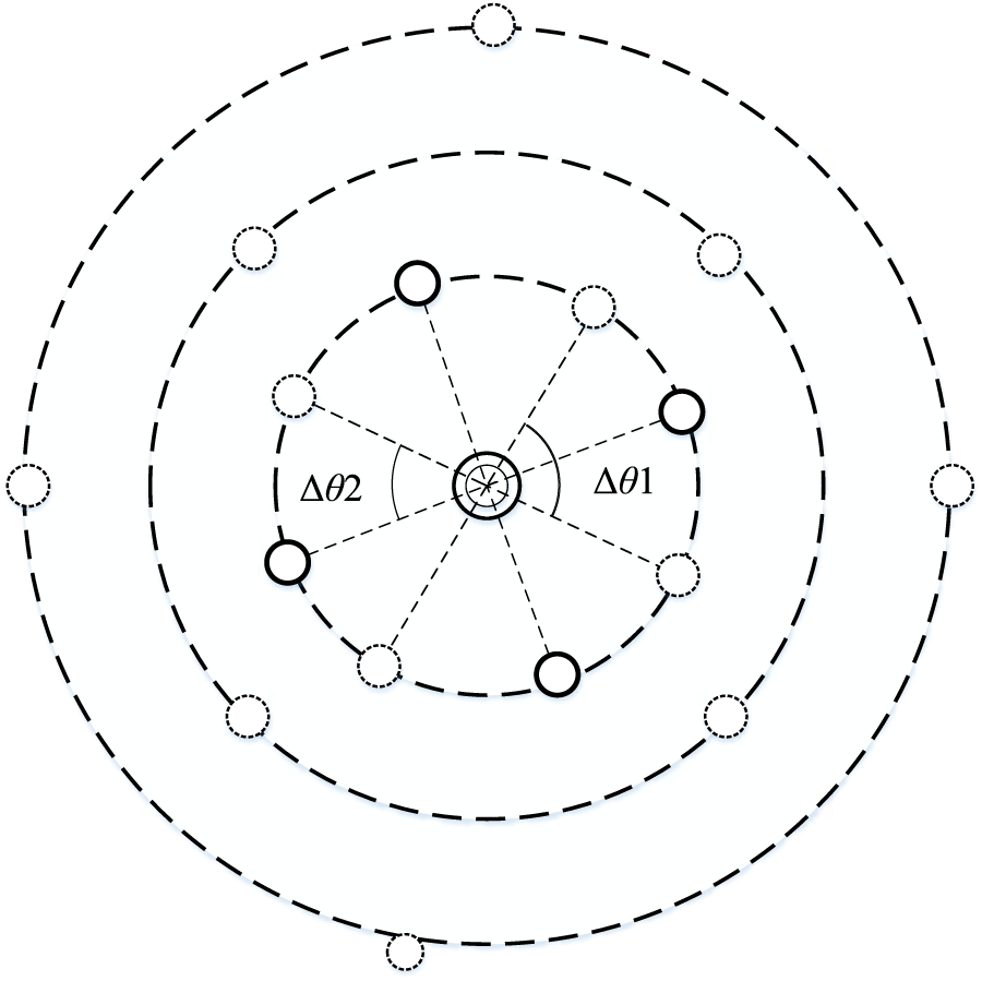
Initial cluster center setting based on center circle set.
4.1.2 Correction of cluster centers
The cluster centers need to be corrected along the tangent direction of the center circle arc. The correction formula and schematic diagram are shown as Figure 3.
FIGURE 3
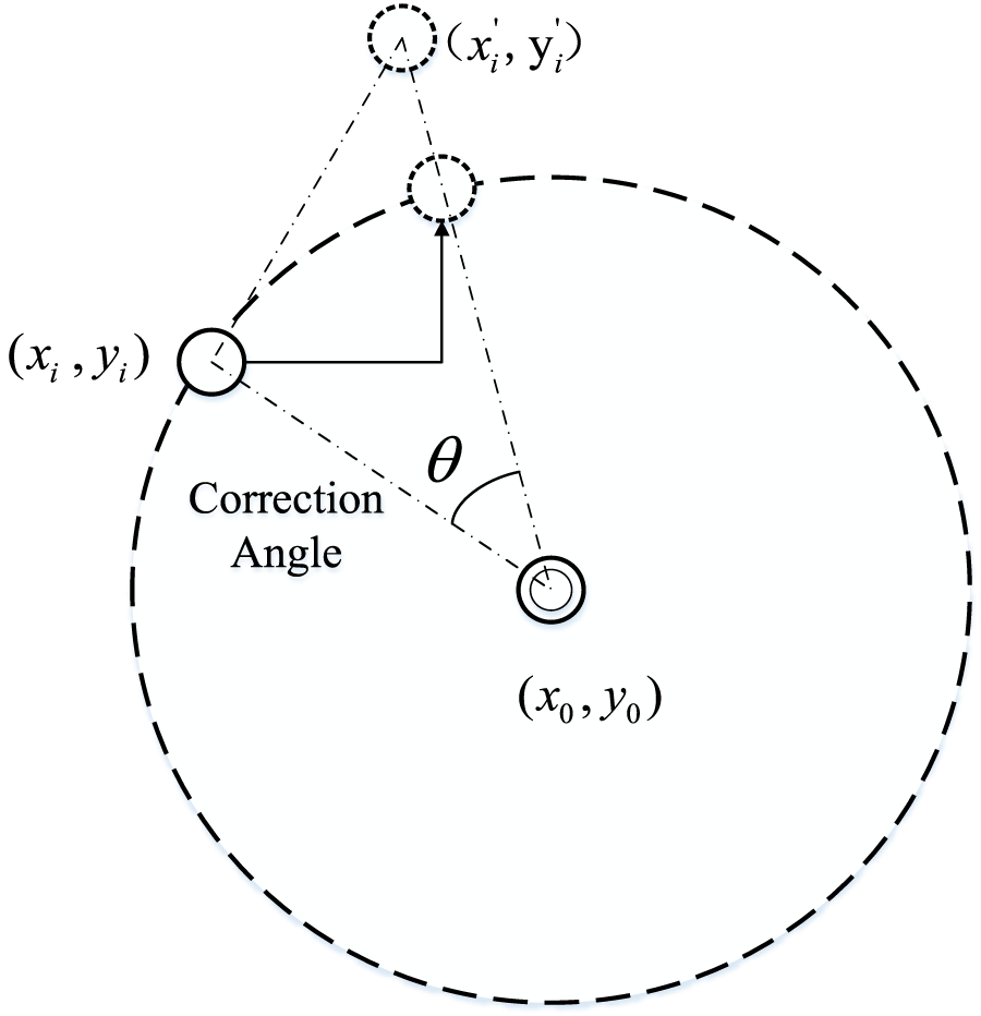
Schematic diagram of cluster center correction.
In the Equation 11, and represent the substation position coordinates. and represent the coordinates of the cluster center before the correction. and represent the geometric center of all source charges in the block after clustering, and the position coordinate of the cluster center after modification becomes the position of the initial cluster center obtained by rotating Angle in the clockwise direction along the arc trajectory of the center.
4.1.3 Calculation of weighted distance between source/load and cluster center
In order to divide loads and DGs into feeder blocks, the Euclidean distance in the traditional K-means algorithm is improved to a weighted distance. The weighted distance is the product of the actual Euclidean distance and two weight factors. The first weight factor characterizes the influence of clustering results on the overall block equilibrium rate. And the second weight factor characterizes the influence of clustering results on the overall block peak-valley difference rate. The specific expressions of loads and DGs weighted distance are shown in Eqs 12–17:
In the equation, and respectively represent the weighted distance and the actual Euclidean distance between the load and the cluster center. and represent the two weight factors of load . represents the peak net load of block . represents the amplification factor. represents the average peak-valley difference of net load in block after load is added to block . If the net load of each block is more balanced and the peak-valley difference within the block is smaller, the weighted distance will be smaller.
In the equation, and respectively represent the weighted distance and the actual Euclidean distance between DG k and the cluster center. and represent the two weight factors of DGk. represents the mean peak-valley difference of block after DGk is added to block . If the net load of each block is more balanced, the smaller the peak-valley difference within the block is, the smaller the weighted distance is.
4.2 Algorithm flow
Based on the concepts defined in
Section 4.1and the proposed algorithmic improvements, the specific steps of the algorithm are designed as follows.
Step 1: Determine a set of initial cluster centers based on the center circle sets, and set the initial values of weighting factors , , , and to 1.
Step 2: Calculate the weighted distances from all loads and DGs to the cluster centers using Eqs 12, 15. Perform clustering of all loads and DGs based on the principle of proximity. Proceed to Step 3.
Step 3: Utilize the centroid adjustment principle proposed to modify the coordinates of cluster centers using Formula 11. Update the weighting factors of all loads and DGs using Formulas, 13, 14, 16. Proceed to Step 4.
Step 4: Determine whether the displacement change of adjacent cluster centers in all blocks satisfies , where represents the displacement change of adjacent centers, and represents the minimum critical displacement value set in this paper. If the condition is satisfied, proceed to Step 5. Otherwise, return to Step 2.
Step 5: Check if all initial cluster centers in the center circle set have been traversed. If yes, proceed to Step 6: otherwise, return to Step 1.
Step 6: Calculate and compare the objective function of division schemes under different initial cluster centers using Eq 3 to obtain the optimal feeder block division scheme.
The Figure 4 illustrates the schematic diagram of the feeder block division algorithm with improved K-means clustering.
FIGURE 4
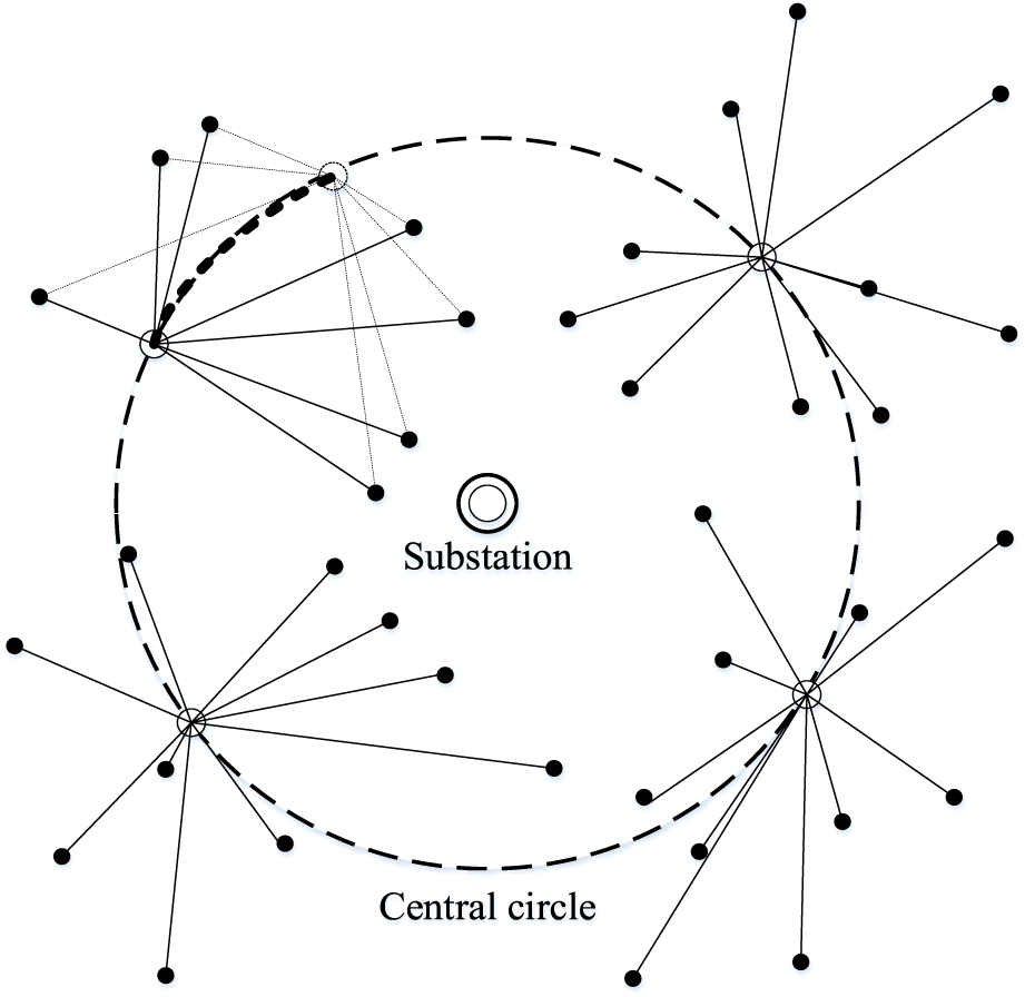
Schematic diagram of improved K-means feeder block division algorithm.
5 Case study
5.1 Case parameters
The case study consists of a power grid formed by three 2 × 63MVA substations, with single busbar connection mode. The maximum load factor for feeder blocks is set to 50%. There is a total of 160, 156, and 150 loads and DGs in the three substations, respectively. The loads include residential, commercial, industrial, and administrative types, while the DGs are photovoltaics. The geographical distribution of the sources and loads is shown in the Figure 5, where the asterisks represent DGs, and the other symbols represent various types of loads.
FIGURE 5
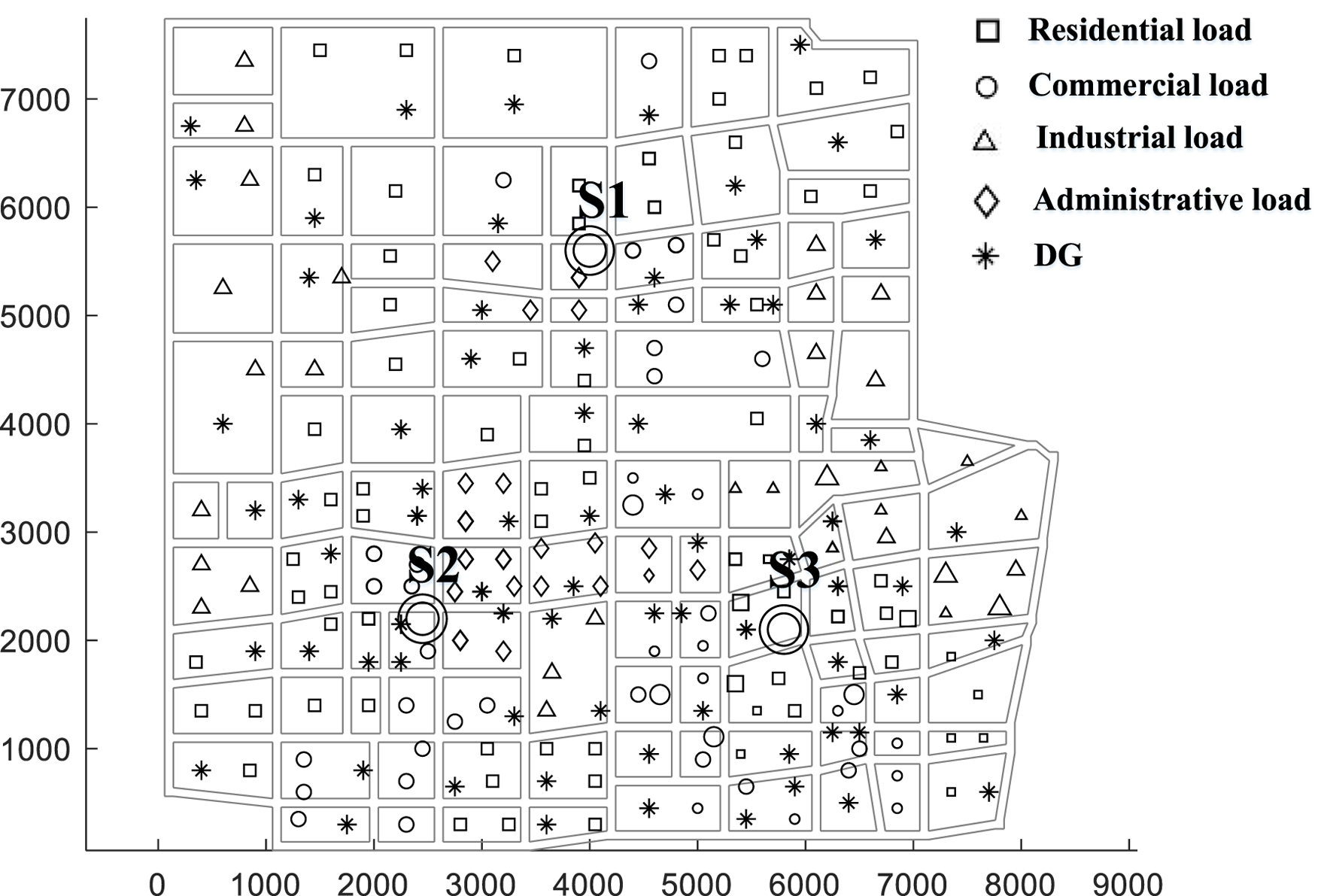
Example geographic information map.
5.2 The impact of source-load complementarity
To analyse the impact of source-load complementarity on feeder block division, two strategies are employed to division the planning area into blocks. Both strategies do not consider the uncertainty of DGs output. The specific strategies are as follows:
Strategy 1: Source-load complementarity is not considered. Only block balance rate is considered, while peak-valley difference rate is not considered. This means that the weighted factor is used in the calculation of weighted distance, while is not used. The improved K-means clustering algorithm is applied to achieve feeder block division.
Strategy 2: Source-load complementarity is considered. Both block balance rate and peak-valley difference rate are comprehensively considered. This means that both weighted factors and are used in the calculation of weighted distance. The improved K-means clustering algorithm is applied to achieve feeder block division.
The division results are compared based on three indicators: the number of blocks, the average balance rate of the blocks, and the peak-valley difference rate . The specific results are shown in the Table 1.
TABLE 1
| Substation | S1 | S2 | S3 | ||||
|---|---|---|---|---|---|---|---|
| Strategy number | Number of feeder blocks | A av1 | A fg1 | A av2 | A fg2 | A av3 | A fg3 |
| 1 | 33 | 9.18 | 2.39 | 9.21 | 2.41 | 9.17 | 2.33 |
| 2 | 30 | 9.67 | 2.65 | 9.75 | 2.71 | 9.66 | 2.59 |
Results of substations block division index under strategy one and strategy two.
Analysis of the data in the table reveals that, considering source-load complementarity, the number of feeder blocks obtained from the substation division is fewer. And the average balance rate and peak-valley difference rate indicators of each substation block are higher.
Therefore, the strategy considering source-load complementarity has several advantages. Firstly, it reduces the number of feeder blocks obtained from division. Predictably, the economic cost of planning is lower. Secondly, it results in higher average balance rate and peak-valley difference rate indicators for each block, which is beneficial for improving the utilization of feeders.
5.3 The impact of confidence level
To analyze the impact of confidence level on the feeder block division scheme, the magnitude of the confidence level is set different. The effects of confidence level on division schemes are shown in the Table 2.
TABLE 2
| Substation | S1 | S2 | S3 | ||||
|---|---|---|---|---|---|---|---|
| ε | Number of feeder blocks | A av1 | A fg1 | A av2 | A fg2 | A av3 | A fg3 |
| 0.95 | 38 | 7.97 | 2.08 | 8.00 | 2.09 | 7.96 | 2.02 |
| 0.97 | 41 | 7.21 | 1.87 | 7.23 | 1.90 | 7.20 | 1.83 |
| 0.99 | 48 | 6.31 | 1.64 | 6.33 | 1.67 | 6.29 | 1.66 |
Comparison of block division effects under different confidence levels.
The data in the table above reveals that, as the confidence level of the chance constraint increases, the number of feeder blocks increases. However, the peak-valley difference and balance rate indicators of each substation decrease. Firstly, according to Eq. 10, the confidence level represents the probability that the maximum load rate constraint condition in the chance constraint holds true. An increase in the confidence level implies stricter constraints on the maximum load rate. To satisfy the maximum load rate constraint, more feeder blocks are obtained. Secondly, as indicated by Eqs 4, 5, smaller peak-valley differences and balance rates result in worse feeder block division results. And the increasing number of feeder blocks leads to decrease in the number of DGs and loads allocated to each individual feeder block. The space for source-load matching is compressed and the effectiveness of the final feeder block division scheme is weakening.
From the analysis above, it is evident that a higher confidence level signifies stricter maximum load rate constraints, resulting in a more conservative feeder block division scheme with lower risk of block overload. However, the increasing number of feeder blocks results in higher planning costs. And the peak-valley characteristics and balance of the feeder blocks are compromised. Therefore, in practical applications, it is essential to set a reasonable confidence level based on the specific requirements of the power grid region.
5.4 The effectiveness analysis of improved K-means clustering algorithm
To validate the effectiveness of the feeder block division algorithm based on the improved K-means clustering proposed in this paper, we compare its performance with the block division results obtained using the algorithm proposed in reference (Shaoyun et al., 2020). Both algorithms are applied to feeder blocks division in the same region, with the same confidence level set for the chance constraints. The division results are illustrated in the following figure.
The two figures above depict the feeder block division results obtained using the algorithm proposed in reference (Shaoyun et al., 2020) and the algorithm proposed in this paper, respectively. In both figures, loads and DGs belonging to the same feeder block are indicated with the same color. Figure 6 reveals that the division results achieved using the algorithm proposed in reference (Shaoyun et al., 2020) exhibit a fan-shaped structure, which meets engineering requirements. Moreover, adjacent feeder blocks are strictly separated by straight line segments, indicating that the loads and DGs near the substation are within the angular range of the fan-shaped structure. Figure 7 shows that the division results obtained using our algorithm still present a fan-shaped region. However, compared to Figure 6, the shapes of the blocks in Figure 7 are more diverse, and the boundaries between adjacent blocks can be separated by a curve.
FIGURE 6
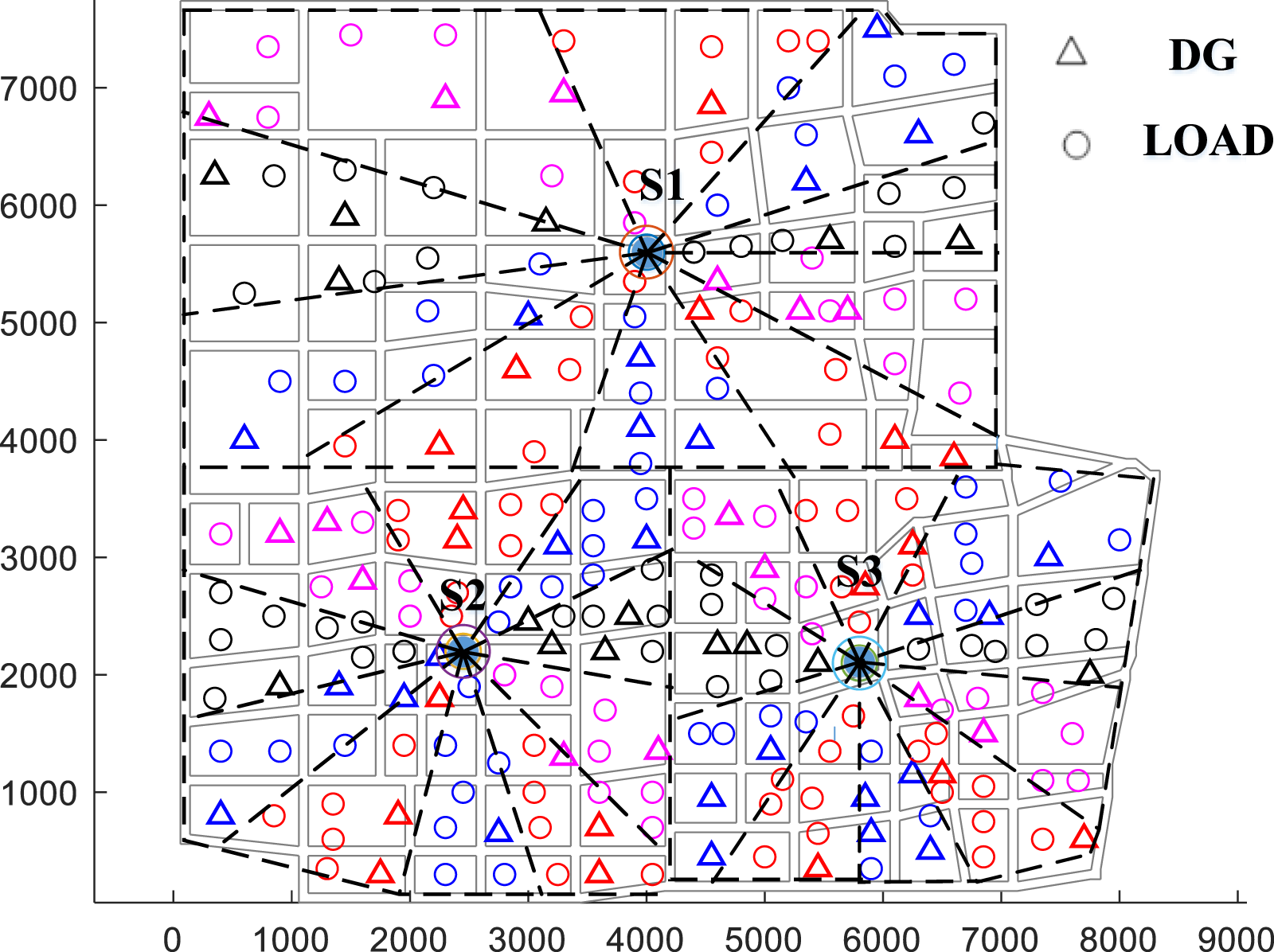
Block division result of the algorithm in reference (Shaoyun et al., 2020).
FIGURE 7
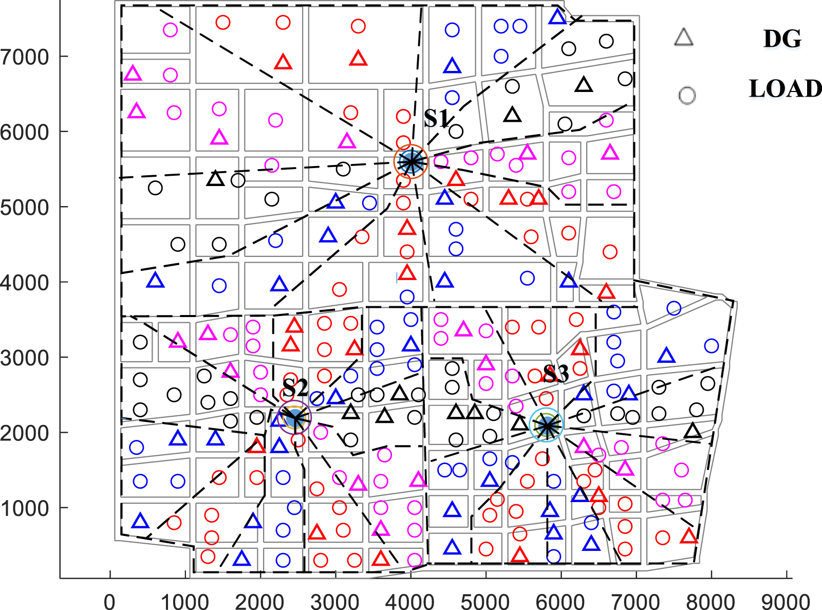
Block division result of improved K-means feeder block division algorithm.
To further demonstrate the superiority of the feeder block division algorithm proposed in this paper, we will analyze the division of a certain DG within the supply area of substation S2. The division results are shown in Figure 8 using the rotating centerline distance-weighted alternating positioning algorithm. While the division results is shown in Figure 9 using the improved K-means clustering algorithm for feeder block division.
FIGURE 8
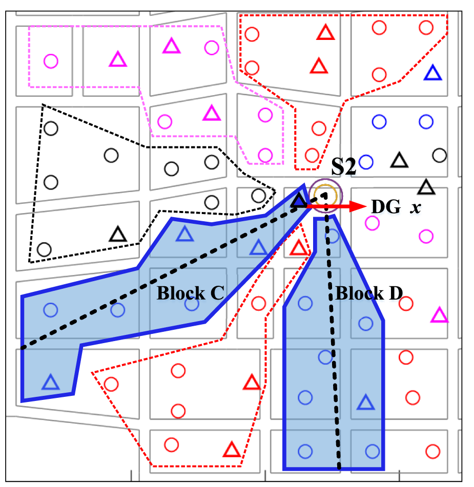
The results of DG x division based on the algorithm in reference (Shaoyun et al., 2020).
FIGURE 9
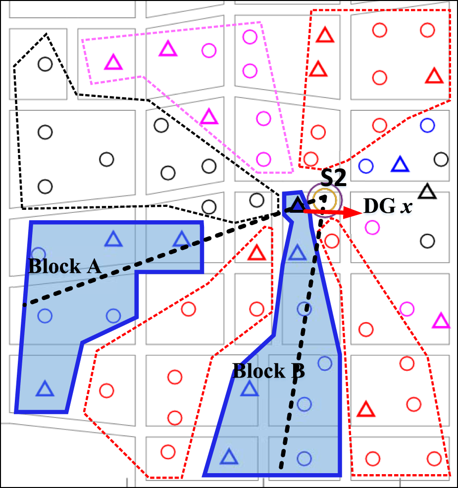
The results of DG x division based on improved K-means feeder block partitioning algorithm.
The analysis focuses on four feeder blocks labeled A, B, C, and D. In both figures, the dashed lines extending from the substations represent the centerline rays proposed in reference (Shaoyun et al., 2020). The x labeled DG represents a distributed generation adjacent to substation S2.
As shown in Figure 8, it is evident that the algorithm proposed in reference (Shaoyun et al., 2020) divisions the blocks based on N centerline rays emanating from the substations. The clustering is obtained by computing the weighted distances from the loads to each centerline. Since the centerlines originate from the substations and the x labeled DG is adjacent to S2, it falls within the dense region of centerline rays, with its trajectory almost overlapping with the centerline of block C. In this scenario, when calculating the weighted distance of this DG, the effect of the weighting factor is severely diminished due to the close proximity to the centerlines. Consequently, the DG is unreasonably assigned to block C, which does not contribute to improving the overall performance of the feeder blocks.
The feeder block division results of the proposed method are shown in Figure 9. This algorithm uses the load clustering center as the reference point and performs clustering based on the weighted distances from the loads to the center. Since the iteration of the load clustering center position is constrained by the center circle, there is no dense clustering center area, addressing the issue of unreasonable load division near the substation. Observing the x labeled DG in Figure 9, it also overlaps with the trajectory of the centerline of block A. But the DG is assigned to block B. This validates that our algorithm, aimed at improving block characteristics, offers more flexibility in load division near the substations.
The results of various indicators for three substations under both algorithms are listed in Table 3. To highlight the superiority and rationality of the algorithm, the chance constraints for both algorithms are set as the same confidence level.
TABLE 3
| Feeder block | S1 | S2 | S3 | ||||
|---|---|---|---|---|---|---|---|
| ε | Division algorithm | A av1 | A fg1 | A av2 | A fg2 | A av3 | A fg3 |
| 0.95 | The algorithm of improved K-means | 7.97 | 2.08 | 8.00 | 2.09 | 7.96 | 2.02 |
| 0.95 | The algorithm in reference (Shaoyun et al., 2020) | 7.85 | 2.05 | 7.92 | 2.04 | 7.88 | 1.93 |
Results of substations block division index under the two algorithms.
As shown in the table, the block division algorithm based on improved K-means clustering demonstrates better effectiveness compared to the algorithm in reference (Shaoyun et al., 2020). The effectiveness and progressiveness of the algorithm is proposed in this paper.
6 Conclusion
A medium-voltage feeder block division model considering the complementary characteristics and uncertainty of DG and loads is established. And a feeder block division algorithm based on improved K-means clustering is proposed. Comparing with existing method, the number of feeder block is reduced. And both block balance rate and peak-valley difference rate are improved. Moreover, with different confidence levels, the feeder block division is different. Higher confidence levels represent stricter maximum load rate constraints, resulting in more conservative block division schemes with lower risk of block overload. With the use of center circle, the division of loads and DGs near the substation is more reasonable.
Statements
Data availability statement
The original contributions presented in the study are included in the article/supplementary material, further inquiries can be directed to the corresponding author.
Author contributions
JZ: Conceptualization, Writing–original draft. ZZ: Methodology, Writing–original draft. YS: Writing–original draft. ZC: Software, Writing–original draft.
Funding
The author(s) declare that financial support was received for the research, authorship, and/or publication of this article. This research was funded by Science and Technology Project of State Grid Fujian Electric Power Co., LTD. (52130N210004).
Conflict of interest
Authors JZ, ZZ, YS, and ZC were employed by Fujian Electric Power Co., LTD., State Grid.
The authors declare that this study received funding from Science and Technology Project of State Grid Fujian Electric Power Co.,LTD. The funder had the following involvement in the study: study design, data collection and analysis, decision to publish, and preparation of the manuscript.
Publisher’s note
All claims expressed in this article are solely those of the authors and do not necessarily represent those of their affiliated organizations, or those of the publisher, the editors and the reviewers. Any product that may be evaluated in this article, or claim that may be made by its manufacturer, is not guaranteed or endorsed by the publisher.
References
1
Baoan X. Baoguo S. Qionghui Li Hu Y. Caixia W. (2022). Rethinking the "three elements of energy" under the "dual carbon. goal Chin. J. Electr. Eng.42 (09), 3 117–3126. 10.13334/j.0258-8013.pcsee.212780
2
Chen C. Zhikeng Li Su Y. (2017). Spatial clustering based grid optimization method for medium voltage distribution network. Sichuan Power Technol.40, 20–23. 04. 10.16527/j.cnki.cn51-1315/tm.2017.04.004
3
Han X. Zhihao Ye Feng Ji (2017). Calculation and analysis of Maximum Power Supply Capacity of ship DC regional distribution System considering motor starting. Proc. CSEE37 (18), 5228–5237+5521. 10.13334/j.0258-8013.pcsee.161547
4
Jun X. Hang Li Bo W. Chenhui S. (2020). Comprehensive matching evaluation method for distributed generation access to urban distribution network Power System. Automation44 (15), 44–51.
5
Li J. Ma B. Zhang Z. Lin Yu Yang X. Research on grid based urban distribution network optimization planning method South Energy Construction, 2015, 2 (03): 38 - 42. 10.16516/j.gedi.issn2095-8676.2015.03.007
6
Li Z. Wu W. Tai X. Zhang B. (2020). A reliability-constrained expansion planning model for mesh distribution networks. IEEE Trans. Power Syst.36 (2), 948–960. 10.1109/tpwrs.2020.3015061
7
Lu Ji Junxiao CHANG Zhang Y. Shiping E. Zeng C. (2020). A two-stage reactive power chance constrained optimization method for active distribution networks considering DG uncertainty. Power Syst. Prot. Control21 (21), 28–35. 10.19783/j.cnki.pspc.210072
8
Sadeghian O. Oshnoei A. Kheradmandi M. Khezri R. Mohammadi-Ivatloo B. A robust data clustering method for probabilistic load flow in wind integrated radial distribution networks[J]. Int. J. Electr. Power and Energy Syst., 2020, 115: 105392, 10.1016/j.ijepes.2019.105392
9
Shaoyun Ge Jun H. Hong L. Yinchang G. U. O. Wang C. (2011). Calculation Method of power supply capacity of distribution System considering main transformer overload and connection capacity constraint. Proc. CSEE31 (25), 97–103. 10.13334/j.0258-8013.pcsee.2011.25.013
10
Shaoyun Ge Qiyuan C. Hong L. Rong L. Kuihua Wu Xiaolei Z. (2020). Practical automatic wiring of medium voltage distribution network considering load characteristic complementarity and power supply unit division. Chin. J. Electr. Eng.40 (03), 790–803. 10.13334/j.0258-8013.pcsee.181013
11
Wang J. Ting S. (2012). Construction of intelligent distribution network evaluation index system. J. North China Electr. Power Univ. Nat. Sci. Ed.39 (06), 65–70.
12
Wang S. Xiang L. Ying Z. (2018). Multi-DG uncertainty modeling and its influence on harmonic power flow in distribution network. Electr. Power Autom. Equip.38 (10), 1–6. 10.16081/j.issn.1006-6047.2018.10.001
13
Xingquan Ji Zheng K. Kejun Li Fu R. Zhu Y. (2016). Application of improved K-means clustering algorithm based on density in distribution network block division. J. Shandong Univ. Eng. Ed.46 (04), 41–46.
14
Xu M. Wang Z. Wang J. Yang F. Xiao B. (2018). Medium voltage distribution network planning based on optimal division of power supply grid. Power Syst. Autom.42 (22), 159–164+186.
15
Zhang M. Wang Z. Qiang Li Sun H. (2019). Power supply zoning optimization model and method in medium voltage target grid planning. Power Syst. Autom.43 (16), 125–131.
16
Zhang X. Chen T. Shuai Z. Kong Y. Liu H. (2020). Construction and calculation of distributed power generation carrying capacity evaluation index system of distribution network. Shandong Electr. Power Technol.47 (11), 19–23.
Summary
Keywords
feeder block division, source-load complementarity, uncertainty, improved K-means clustering, medium-voltage distribution network
Citation
Zheng J, Zhang Z, Shi Y and Chen Z (2024) Medium-voltage feeder blocks division method considering source-load uncertainty and characteristics complementary clustering. Front. Energy Res. 12:1452011. doi: 10.3389/fenrg.2024.1452011
Received
20 June 2024
Accepted
24 July 2024
Published
07 August 2024
Volume
12 - 2024
Edited by
Yonghui Sun, Hohai University, China
Reviewed by
Yuanyuan Chai, Hebei University of Technology, China
Junpeng Zhu, Hohai University, China
Feng Liang, Shandong University of Technology, China
Updates
Copyright
© 2024 Zheng, Zhang, Shi and Chen.
This is an open-access article distributed under the terms of the Creative Commons Attribution License (CC BY). The use, distribution or reproduction in other forums is permitted, provided the original author(s) and the copyright owner(s) are credited and that the original publication in this journal is cited, in accordance with accepted academic practice. No use, distribution or reproduction is permitted which does not comply with these terms.
*Correspondence: Jieyun Zheng, zjy2580001219@163.com
Disclaimer
All claims expressed in this article are solely those of the authors and do not necessarily represent those of their affiliated organizations, or those of the publisher, the editors and the reviewers. Any product that may be evaluated in this article or claim that may be made by its manufacturer is not guaranteed or endorsed by the publisher.