 Panisetty Sreenivasulu
 Jakeer Hussain*
- Vellore Institute of Technology, School of Electrical Engineering, Vellore, Tamilnadu, India
This paper presents the protection of the rotor side converter in a grid-connected doubly fed induction generator (DFIG)-based wind energy conversion system (WECS) during a symmetrical voltage dip. In order to manage rotor current and regulate DC link voltage, an efficient active crowbar protection circuit is implemented in the rotor side converter (RSC). To improve the low-voltage ride-through capability for grid-connected wind turbine systems, an integrated DFIG-based WECS role is crucial because wind turbines must remain connected to the utility grid during faults to ensure continuity and reliability of power supply. This paper aims to design and implement an efficient active crowbar protection technique to protect the RSC and avoid excessive rotor current during a symmetrical voltage dip. Therefore, the efficient active crowbar protection circuit is designed using MATLAB-Simulink software, and its performance is validated using a real-time (RT) simulator. Finally, the existing methods are compared with the proposed work outcomes, and a conclusion is made.
1 Introduction
The depletion of non-renewable energy sources and increasing levels of environment-unfriendly emissions have raised concerns in recent times. Hence, renewable energy sources have very important roles in meeting the demand for electrical energy. Wind energy is a vital and renewable source of electrical energy (Joshuva and Sugumaran, 2020); in several countries, wind turbines are used as significant intermittent renewable energy sources to decrease energy prices and eliminate the use of fossil fuels. Power generation using wind turbines can reduce pollution and carbon dioxide emissions; hence, it is a rapidly expanding activity that will continue to improve as more nations implement power generation plants using wind turbines in the future (Ganthia and Barik, 2022). Wind turbines are categorized as horizontal- and vertical-axis types. Of these, horizontal-axis wind turbines have better market demand worldwide because of their better power efficiency compared to vertical-axis wind turbines (Ullah et al., 2017). Wind turbines contribute significantly to power generation because of their variable-speed and fixed-speed operational flexibility; however, variable-speed operation generates more wind energy than the fixed-speed operation (Hussain and Mishra, 2016).
Doubly fed induction generators (DFIGs) are the most common type of generators used in wind energy conversion systems (WECSs) owing to their numerous advantages. These advantages include the ability to operate at variable speeds, torque and power control capabilities, reduced power converter costs, maximum power tracking features, limited speed range, and partial ratings. The DFIG-based WECS is gaining popularity in the small-power wind turbine segment owing to its ability to operate at variable speeds for maximum efficiency (Hussain and Mishra, 2014b). The power converter typically transfers only 25%–30% of the rated power, while the rest is transmitted directly to the power grid. The DFIG has two connections: a stator connection that is directly fed to the grid and a rotor connection that is joined through two back-to-back power converters (Yang and Jin, 2020). Furthermore, DFIGs operate in two modes, namely, subsynchronous and hypersynchronous modes. The power transferred to and received from the grid depends on the DFIG’s rotor speed; if the rotor speed is less than the synchronous speed, the operation is in the subsynchronous mode, and power is transferred from the grid to the DFIG through a back-to-back power electronic converter. On the other hand, if the rotor speed is greater than the synchronous speed, the operation is in the hypersynchronous mode, and power is transferred from the DFIG to the utility grid (Naidu and Singh, 2016). The DFIG’s rotor is directly connected to the rotor-side converter (RSC) to control the rotor speed and transfer energy bidirectionally (Puchalapalli and Singh, 2020; Ma et al., 2020). Various investigators have evaluated the performances of WECSs during symmetrical grid voltage dips and contingencies (Yunus et al., 2020).
During and after system failures involving changes in frequency and voltage, wind turbines are required to remain connected to the utility grid. To overcome these issues, low-voltage ride-through (LVRT) capabilities have been introduced (Pathak et al., 2020; Jabbour et al., 2020). A passive crowbar circuit permits the switch to close but not open until the sudden increase in the crowbar current decreases. Contingencies occurring at the utility grid can be avoided through efficient active crowbar protection (EACP) circuitry, which are commonly employed in electronic devices to prevent high-voltage events from affecting sensitive components, such as semiconductor switches comprising diodes, insulated-gate bipolar transistors (IGBTs), and resistors. Thus, this circuit enables transfer of electricity to the utility grid during voltage dips to improve grid stability (Dhanraj et al., 2021).
The term “voltage dip” refers to a significant drop in voltage over hundreds of milliseconds. Initially, electrical grid faults were responsible for separation of the wind turbine machinery from the utility grids owing to different problems, such as symmetric grid voltage dips, asymmetric grid voltage dips, and various grid disturbances. Voltage dips can be divided into balanced and unbalanced three-phase grid voltage dips (Laafou et al., 2023). The DFIG and wind turbine condition capabilities are only investigated during balanced voltage dips. If the system experiences a sudden symmetric grid voltage dip, the DC bus voltage will decrease to its rated limit, potentially damaging the DC bus capacitor and RSC switches. Therefore, activating the EACP circuit protects the RSC and mitigates the peak rotor current and DC link capacitance. Once the voltage dip in the system is rectified, power flows in a nominal state (Zandzadeh and Vahedi, 2014). The voltage dip behaviors of the DFIG with and without EACP have been investigated, and a rising rotor current was observed. Furthermore, reactive power must be delivered to the utility grid during a symmetric voltage dip to support voltage restoration. This work discusses the design of an EACP circuit based on the rotor current flow; the goal here is to help improve system performance as well as ensure service continuity and power network connectivity during and after balanced voltage fluctuations.
The significant contributions of this study are as follows:
1. To reduce the rotor current faults.
2. To maintain steady DC link voltage across the converter.
3. To improve the rapid reaction of the terminal voltage.
4. To enhance the quick response of the DFIG.
The remainder of this paper is organized as follows. Section 2 discusses the system configuration and modeling, while Section 3 presents the design of the EACP circuit. Section 4 presents the control strategy for the EACP system, and Section 5 explains the experimental OPAL-RT real-time simulator setup. Section 6 presents the MATLAB simulations and experimental results, and Section 7 presents the conclusions and future scope of this work.
2 DFIG-based wind turbine system configuration and modeling
A typical grid-connected DFIG-based wind turbine system is shown in Figure 1. This configuration includes a horizontal-axis wind turbine connected to a DFIG wind turbine generator through a gear system. The DFIG stator winding is directly connected to the utility grid, and the rotor winding is connected to the same grid through bidirectional power converters (Hussain and Mishra, 2014a).
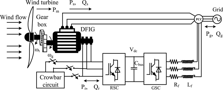
Figure 1. Schematic illustration of the DFIG-based wind turbine system.
2.1 Wind turbine modeling and characteristics
The turbine of the WECS is a vital component for capturing kinetic energy from the wind and converting it into mechanical energy (Kasbi and Rahali, 2021). Wind turbines rotate when exposed to air flow and produce mechanical power as follows:
where
where
where
in which
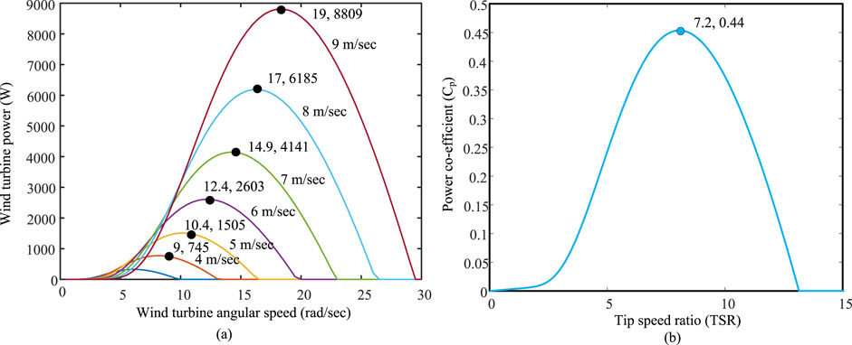
Figure 2. (A) Modeling characteristics of the wind turbine and (B) tip speed ratio (TSR) vs. power coefficient.
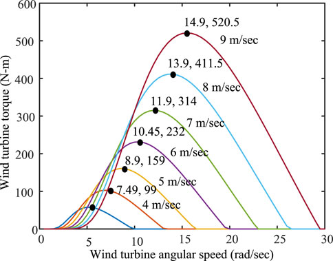
Figure 3. Turbine speed vs. torque characteristics.
2.2 Modeling of the DFIG
The vector control strategy requires that the DFIG model be in a synchronous
The rotating synchronous
The rotating synchronous
Here,
The active and reactive power expressions of the stator and rotor in the rotating
The electromagnetic torque is given by
where
3 Design of the EACP circuit
The EACP circuit protects the RSC against overcurrents. The crowbar circuit creates a low-resistance or short-circuit condition across the generator and RSC. The EACP device circuit including the resistor, diodes, and IGBTs is shown in Figure 4. This device is activated by a current-limiting circuit in the active crowbar circuit. During a voltage dip, the rotor overcurrent destroys the power converter in a few milliseconds, so the EACP circuit is used to prevent this destruction. The EACP circuit operation uses the gate turn-on and turn-off signals of the IGBTs. The gate signals are applied to the IGBTs to protect them against overvoltages in the stator and overcurrents in the rotor (Gencer, 2018).
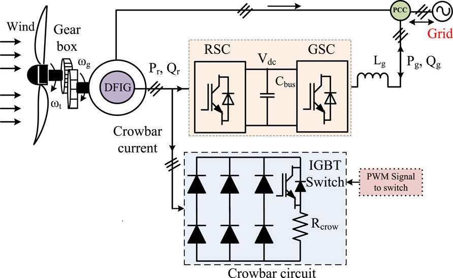
Figure 4. Schematic illustration of the efficient active crowbar protection (EACP) circuit.
3.1 Symmetric voltage dips
Voltage dips are defined as sudden decreases in the grid voltage ranging from a cycle to a second or a few hundred milliseconds that affect the grid voltage by up to 10% of the nominal value (called the dip voltage). The voltage drop must typically be between 1% and 90% of the nominal voltage, although any decrease in the voltage drop less than 1% is regarded as a transient interruption. In a balanced dip, the voltage is reduced equally on all lines, whereas an unbalanced dip causes unequal voltage reductions on different lines.
3.2 Stator flux analysis
Voltage dips are sudden drops in the grid voltage caused by contingencies or faults in the utility grid. This work focuses only on symmetric grid voltage dips. When the voltage dips, it is sensed immediately in the DFIG stator; the DFIG can analyze the flux within the stator to determine the faults caused by voltage dips. In such events, the flux behaviors must be investigated to understand the issues arising from dip interruptions (Garkki and Revathi, 2024). The expression in Equation 10 is used to compute the flux.
When the voltage dips suddenly, the flux will not reach the same final steady state as the stator voltage. Each phase flux is the sum of sinusoidal and exponential components with a time constant
Equation 11 is obtained from the circuit depicted in Figure 5A:
The rotor current depends on the stator flux, equivalent resistance, inductance, rotor voltage, and stator voltage. Hence, the space vector diagram at subsynchronous speed is as illustrated in Figure 5B. The sum of the main terms
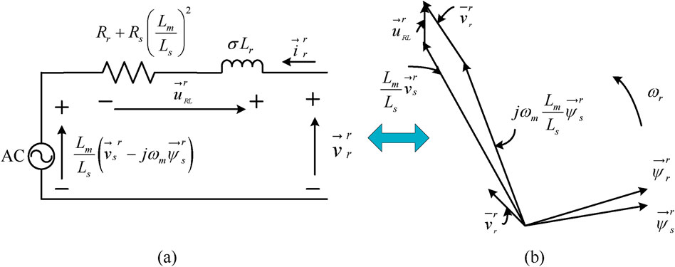
Figure 5. (A) Equivalent circuit of the DFIG for analyzing grid voltage dips; (B) vector diagram for the subsynchronous generator mode.
4 Control strategy for the EACP system
The EACP system improves the LVRT capability of the WECS. When a sudden symmetric grid voltage dip occurs in the network, the rotor current increases because of magnetic coupling between the DFIG stator and rotor windings, making the stator and rotor currents more transient. Furthermore, the rotor is short-circuited by activating the EACP circuit to protect the RSC. This work aims to limit the stator and rotor currents during sudden grid voltage variations using the EACP circuit. Therefore, the control strategy for the RSC, grid-side converter (GSC), and active crowbar circuit should be designed such that the protection circuit is enabled and regulates the real and reactive powers during voltage dips.
4.1 RSC strategy
The block diagram of the RSC control strategy is depicted in Figure 6 and consists of the inner and outer loop control methods for controlling the real and reactive powers. The Clark transformation technique involves transfer from three phase to two phase (i.e., abc to
where
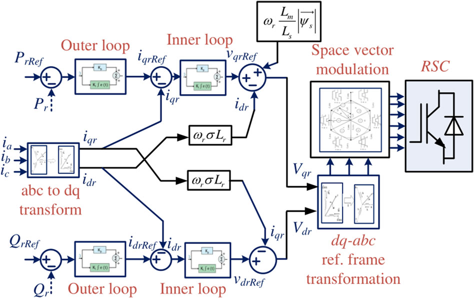
Figure 6. Schematic strategy for rotor-side control.

Figure 7. Synchronous rotating
4.2 GSC strategy
The GSC control strategy is depicted in Figure 8 and regulates both the DC link voltage and reactive power (Yang and Jin, 2020). This control strategy consists of inner and outer loops, where the inner loop is faster to allow current tracking, while the outer loop is relatively slower for reactive power regulation. Here, the reactive power
where
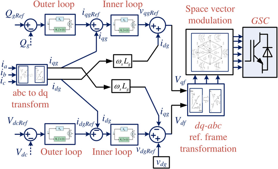
Figure 8. Schematic control strategy for the grid-side converter (GSC).
The simplified real and reactive powers exchanged with the utility grid are as given by Equation 18 (Ali et al., 2020).
Thus, the rotating direct
4.3 Active crowbar circuit control strategy
This control strategy requires reactive power during the grid voltage dip to help with voltage recovery. The active crowbar circuit is a protection system commonly used in power electronics to protect components such as IGBTs, metal-oxide-semiconductor field-effect transistors, and other delicate power semiconductor devices under excess voltage conditions. Upon detecting a grid voltage dip, the crowbar circuit rapidly transfers any unused energy, thereby mitigating damage to the protected components.
The control strategy of the active crowbar circuit is depicted in Figure 9. This protection circuit is important for controlling the rotor current in the event of a sudden dip in the grid voltage. Grid voltage dips can be caused for the following reasons:
The active crowbar circuit comprises an IGBT connected in series with a resistor and placed across a bridge diode. At the instant when the voltage fluctuation occurs in the grid, the active crowbar circuit control sends a PWM signal to the IGBT switch; this protects the RSC by controlling the wide variations in the rotor current. During a grid fault, the rotor current suddenly increases and may damage the RSC; then, the active crowbar circuit turns on the IGBT control switch and regulates the current to protect the converter.
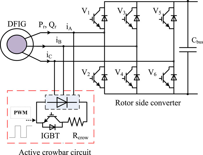
Figure 9. Control strategy of the active crowbar circuit.
The IGBT is turned off when the stator voltage drops below a predetermined threshold. Next, a carefully designed process is used to restore the RSC operation quickly. The semiconductor devices switch off the active crowbar circuit when the grid voltage is at the standard level. Thereafter, the wind power system operates normally (Sreenivasulu and Hussain, 2023; Uddin et al., 2023).
During a symmetric voltage dip, the peak rotor current flows through the semiconductor devices in the EACP circuit. Thus, the IGBT in the active crowbar circuit protects the RSC and maintains the voltage as given by Equation 20 (Hussain and Mishra, 2015):
where
5 Experimental OPAL-RT simulator setup
The EACP circuit for the DFIG-based WECS was verified through MATLAB simulations using the real-time (RT) simulator OP5700 (RT-LAB, MSOx3014T), a field-programmable gate array (FPGA) on a VC707 board, a programmable control board (PCB), and probes for interfacing between MATLAB/Simulink and OPAL-RT simulator to provide the analog outputs and digital inputs. Figure 10 depicts the laboratory setup of the RT digital simulator. The generator and controller are retained in the OPAL-RT digital simulator so that the system operates according to its clock because of the high-speed OPAL-RT sample speed of 18 ns to a few microseconds. This timing is used for the prototype editing, building, loading, and execution stages. Table 1 summarizes the parameters of the RT digital simulator in the OPAL system.
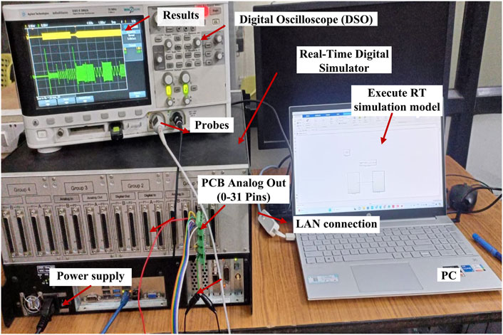
Figure 10. Experimental real-time simulator setup.
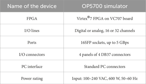
Table 1. Specifications of the real-time simulator.
6 Results and discussion
The design and implementation of the EACP circuit were discussed for a symmetric grid voltage dip. This was also simulated using MATLAB/Simulink and tested through the OPAL-RT simulator. The parameters and values of the 5-kW DFIG and wind turbine systems are listed in Tables 2, 3.
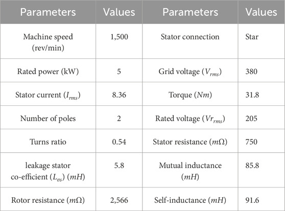
Table 2. DFIG parameters and values.
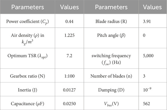
Table 3. Wind turbine model parameters and values.
6.1 Simulation results
The RSC is protected by the EACP circuit to improve the operation of the DFIG based on the WECS during balanced grid voltage dips. The RSC improves the reactive power requirements during grid faults and tracks the DFIG’s rotor and reference speeds in the same manner. Therefore, the power converter supports extraction of maximum power from the wind turbine.
The GSC maintains
The simulation results of the DFIG-based WECS were observed without and with the protection circuit for symmetric grid voltage dips. The design is intended to not operate the protection circuit when a fault occurs in the power grid, even if the voltage at the PCC decreases to 0. The performance of the DFIG system with a balanced three-phase fault is shown in Figure 11. As shown in Figure 11A, a grid voltage fluctuation occurs at 3–3.5 s after clearing the dip, and the grid voltage recovery time is 0.67 s (3.5–4.17 s) to reach the nominal state. Figure 11B illustrates that the rotor current increases to 100 A without activating the protection circuit. Thus, the peak rotor current must be decreased to protect the RSC, and the protection circuit should be activated. The changes in the signals are shown in Figures 12A–D. Figure 12A illustrates the grid voltage during a sudden grid fault; Figure 12B shows that the crowbar current spikes to 30 A by triggering the protection circuit alone. The RSC is then isolated from the network during activation of the crowbar circuit upon occurrence of a sudden grid voltage dip. During the balance fault incident, the rotor current flowing into the crowbar circuit reaches a maximum value of 30 A, and the active crowbar circuit operates for 3–3.5 s. Following the dip, the crowbar current returns to a steady level. In the simulation, the crowbar resistance used was 0.2 Ω. Hence, when the voltage recovers over the interval of 3.5–4.17 s, the rotor current becomes steady once the voltage dip is restored. Figure 12C shows the three-phase rotor current during the balanced three-phase fault condition in which the three-phase rotor current is supplied to the power grid; when a sudden fault occurs in the system, the rotor current falls instantaneously to 25 A upon activation of the protection circuit. Figure 12D clearly illustrates the activation time of the voltage dip. Figures 13A, B show the grid voltage and corresponding bus voltage during a sudden voltage dip. Figure 13A shows the grid voltage as explained above. Figure 13B illustrates that the reference and measured voltages are the same; however, the bus voltage decreases from 560 V to 481 V, and the duration changes from 3 to 4.4 s during the grid voltage disturbance. Figure 14A shows the system grid voltage discussed in the earlier sections. Figure 14B depicts the bus voltage decrease from 560 V to 530 V and the interval of 3–4.3 s by triggering of the EACP circuit. Hence, the system is protected from overcurrents.
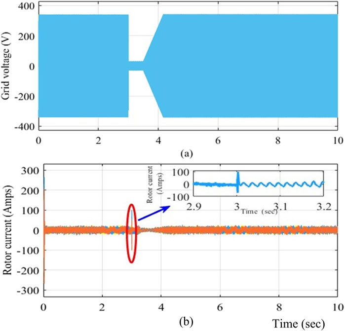
Figure 11. (A) Grid voltage and (B) three-phase rotor current without the crowbar circuit.
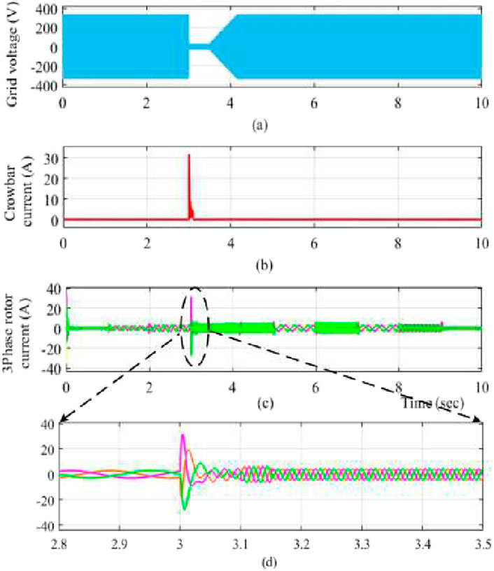
Figure 12. (A) Grid voltage; (B) crowbar current; (C) three-phase rotor current; (D) specific duration of the rotor current.
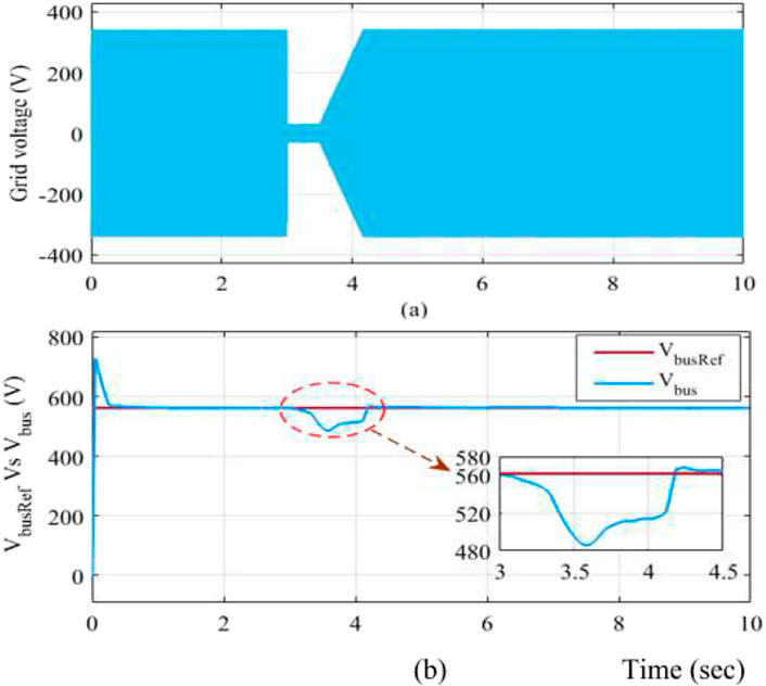
Figure 13. (A) Grid voltage and (B) bus voltage (
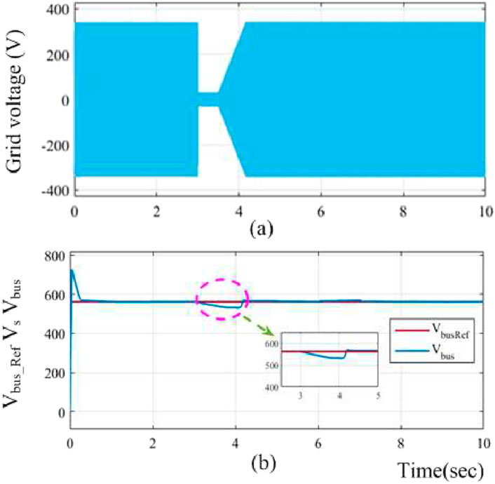
Figure 14. (A) Grid voltage and (B) bus voltage (
Table 4 compares some previous works with and without the protection circuit for the rotor current in the symmetric voltage dip analysis. Furthermore, it discusses the same grid voltage fault conditions with an active crowbar circuit; the difference in rotor currents with and without the active crowbar circuit shows that the rotor current magnitude is maximally reduced by the EACP circuit for the symmetric voltage dip. Table 5 quantitatively compares data from other works implementing the EACP control strategy. Kaloi et al. (2019) focused on enhancing the LVRT capability, and their feedback linearization controller offers only RSC protection and DC link voltage maintenance. Ganthia and Barik (2022) studied PI control techniques, and fuzzy logic controllers were used to protect the network. The proposed control strategy in this work can mitigate the rotor current while protecting the RSC circuit. Therefore, when the EACP circuit is active, the rotor current can be controlled; these effects were verified through simulations in MATLAB/Simulink and a real-time experiment using the OPAL-RT 5700 simulator with and without the protection circuit.
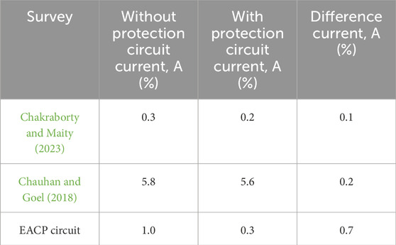
Table 4. Conventional and designed protection circuits for rotor current (comparisons based on only the rotor current in ampere).
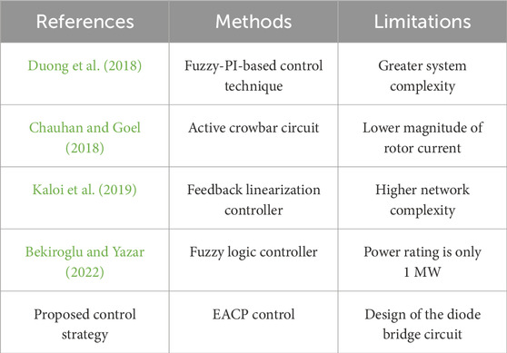
Table 5. Quantitative data comparisons.
6.2 Experimental results
The RT digital simulations include results obtained at various wind velocities. Figure 10 shows the experimental setup demonstrating how the MATLAB model is converted to a C language program through FPGA-based prototyping to achieve RT execution. By altering the fixed-mode parameters, ode4-type solver (Runge–Kutta), and sample time of 10 µs, the DFIG-based wind turbine model and control strategy were written in C language and implemented using Simulink S-function blocks. The wind turbine emulator results were tested using MATLAB/Simulink software with specific blocks from the OPAL-RT library. These blocks are mainly used for communication and control between the simulation and RT hardware. Figure 15 illustrates the three-phase rotor current during a symmetric grid voltage dip. Figure 16 shows that the rotor current spikes to 99.6 A during the sudden grid voltage dip when the protection circuit is not activated. The RSC may be damaged in this particular interval. Thus, the EACP circuit is introduced to protect the RSC and DC link capacitor. Furthermore, from 3 to 4.17 s, the rotor current has a higher frequency and shorter period, i.e., 1.6 s, due to the grid voltage fault. We observe the rotor current frequency by expanding over a particular period, i.e., 7 s of rotor current. Figure 17 shows that the rotor current spikes to 28 A at 0.2 s upon activation of the crowbar circuit in response to the grid voltage disturbance; we also show the enlarged rotor current over a duration of 0.5 s. When the EACP circuit is activated, the increasing rotor current passes through the crowbar circuit, so the RSC is demagnetized for a few seconds to clear the fault. When the fault is resolved, the rotor current resumes a steady state; this is observed in the expanded duration of the rotor current, i.e., 1.4 s. Figure 18 depicts the measured DC link voltage change of 560 V, whose magnitude then decreases by 60 V after 0.6 s following the grid voltage dip. The reference grid voltage of 561 V and measured grid voltage are the same under normal conditions. Figure 19 illustrates that the DC link voltage decreases by a small magnitude of 35 V upon activation of the EACP circuit. Similarly, the crowbar current is observed to be 25 A at 1.2 s after the sudden grid voltage dip upon activation of the protection circuit.

Figure 15. Three-phase rotor current during a symmetric voltage dip.
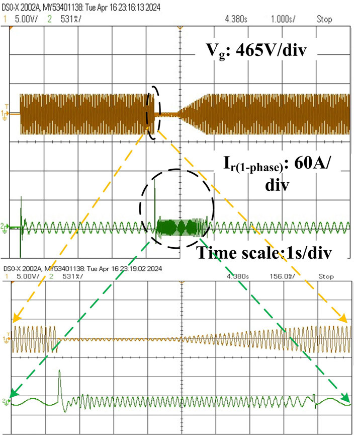
Figure 16. Three-phase rotor current without the crowbar circuit.
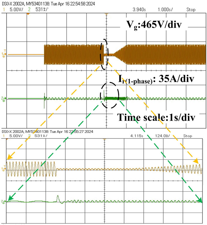
Figure 17. Three-phase rotor current with the crowbar circuit.
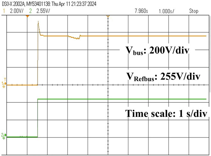
Figure 18. Responses of the reference bus voltage
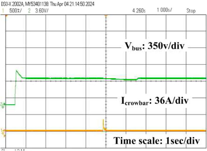
Figure 19. Crowbar current with the active crowbar protection circuit.
7 Conclusion and future scope
This work explores integration of DFIG wind turbines into the grid to ensure stable operation during voltage dips. Furthermore, we evaluate the performance of an improved active crowbar protection circuit to mitigate the LVRT capability of the DFIG-based WECS. The operational principle of the EACP circuit allows protecting the RSC and DC link capacitor against symmetric voltage dips. The results show that the peak rotor current and DC link voltage ripple are successfully limited by the EACP circuit while allowing real and reactive power controls. The EACP circuit performance was evaluated through simulations in MATLAB/Simulink and further validated by RT experiments on an OPAL-RT 5700 simulator. As demonstrated, the voltage dip response from 3 to 4.17 s confirms the ability of the EACP circuit to enhance the DFIG’s LVRT capability. Additional research can be conducted for applications involving further optimizations related to responses to unbalanced voltage dips as well as EACP circuit design for various grid fault situations.
This study comprehensively explores the development, implementation, and validation of protective mechanisms to protect the RSC in a DFIG-based WECS during symmetric and unsymmetric voltage dips. Future prospects for this work encompass topics concerning the essential parameters, such as overcurrent and overvoltage protection as well as improvements to the control systems using machine learning, artificial intelligence, real-time monitoring, and adherence to grid standards.
Data availability statement
The original contributions presented in this study are included in the article/supplementary material, and any further inquiries may be directed to the corresponding author.
Author contributions
PS: conceptualization, methodology, resources, validation, writing–original draft, writing–review and editing, formal analysis, and supervision. JH: formal analysis, funding acquisition, project administration, software, supervision, writing–original draft, and writing–review and editing.
Funding
The authors declare that financial support was received for the research, authorship, and/or publication of this article. This research was supported by the Seed Grant Product Development Scheme (SG20210242) of Vellore Institute of Technology, Vellore, India.
Acknowledgments
The authors wish to acknowledge Vellore Institute of Technology for aiding their research efforts.
Conflict of interest
The authors declare that the research was conducted in the absence of any commercial or financial relationships that could be construed as a potential conflict of interest.
Publisher’s note
All claims expressed in this article are solely those of the authors and do not necessarily represent those of their affiliated organizations or those of the publisher, editors, and reviewers. Any product that may be evaluated in this article or claim that may be made by its manufacturer is not guaranteed or endorsed by the publisher.
References
Abu-Rub, H., Malinowski, M., and Al-Haddad, K. (2014). Power electronics for renewable energy systems, transportation and industrial applications. John Wiley and Sons.
Ali, M. M., Youssef, A.-r., Ali, A. S., and Abdel-Jaber, G. (2020). Variable step size PO MPPT algorithm using model reference adaptive control for optimal power extraction. Int. Trans. Electr. Energy Syst. 30, e12151. doi:10.1002/2050-7038.12151
Bekiroglu, E., and Yazar, M. D. (2022). “Improving fault ride through capability of DFIG with fuzzy logic controlled crowbar protection,” in 2022 11th International Conference on Renewable Energy Research and Application (ICRERA), Istanbul, Turkey, September 18–21, 2022 (IEEE), 374–378.
Chakraborty, A., and Maity, T. (2023). An adaptive fuzzy logic control technique for LVRT enhancement of a grid-integrated DFIG-based wind energy conversion system. ISA Trans. 138, 720–734. doi:10.1016/j.isatra.2023.02.013
Chauhan, D., and Goel, S. (2018). Designing of advanced crowbar protection system for DFIG coupled wind energy conversion system at different fault conditions. Int. J. Sci. Technol. and Eng. 4, 119–125.
Dhanraj, J. A., Mostafaeipour, A., Velmurugan, K., Techato, K., Chaurasiya, P. K., Solomon, J. M., et al. (2021). An effective evaluation on fault detection in solar panels. Energies 14, 7770. doi:10.3390/en14227770
Duong, M. Q., Leva, S., Mussetta, M., and Le, K. H. (2018). A comparative study on controllers for improving transient stability of DFIG wind turbines during large disturbances. Energies 11, 480. doi:10.3390/en11030480
Fateh, F., White, W. N., and Gruenbacher, D. (2015). A maximum power tracking technique for grid-connected DFIG-based wind turbines. IEEE J. Emerg. Sel. Top. Power Electron. 3, 957–966. doi:10.1109/jestpe.2015.2448633
Ganthia, B. P., and Barik, S. K. (2022). Fault analysis of PI and fuzzy-logic-controlled DFIG-based grid-connected wind energy conversion system. J. Institution Eng. (India) Ser. B, 415–437. doi:10.1007/s40031-021-00664-9
Garkki, B., and Revathi, S. (2024). Direct speed fractional order controller for maximum power tracking on dfig-based wind turbines during symmetrical voltage dips. Int. J. Dyn. Control 12, 211–226. doi:10.1007/s40435-023-01259-6
Gencer, A. (2018). Analysis and control of fault ride through capability improvement pmsg based on wecs using active crowbar system during different fault conditions. Elektron. Ir. Elektrotechnika 24, 63–69. doi:10.5755/j01.eie.24.2.20637
Hussain, J., and Mishra, M. K. (2014a). “Adaptive MPPT control algorithm for small-scale wind energy conversion systems,” in 2014 IEEE International Conference on Power Electronics, Drives and Energy Systems (PEDES), Mumbai, India, December 16–19, 2014 (IEEE), 1–5.
Hussain, J., and Mishra, M. K. (2014b). “Design and development of real-time small-scale wind turbine simulator,” in 2014 IEEE 6th India International Conference on Power Electronics (IICPE), Kurukshetra, India, December 08–10, 2014 (IEEE), 1–5.
Hussain, J., and Mishra, M. K. (2015). “Design and control process of SEPIC converter for maximum power extraction in wind energy conversion systems,” in IECON 2015-41st Annual Conference of the IEEE Industrial Electronics Society, Yokohama, Japan, November 09–12, 2015 (IEEE), 000655–000660.
Hussain, J., and Mishra, M. K. (2016). Adaptive maximum power point tracking control algorithm for wind energy conversion systems. IEEE Trans. Energy Convers. 31, 697–705. doi:10.1109/tec.2016.2520460
Hussain, J., and Mishra, M. K. (2019). An efficient wind speed computation method using sliding mode observers in wind energy conversion system control applications. IEEE Trans. Industry Appl. 56, 730–739. doi:10.1109/tia.2019.2942018
Jabbour, N., Tsioumas, E., Mademlis, C., and Solomin, E. (2020). A highly effective fault-ride-through strategy for a wind energy conversion system with a doubly fed induction generator. IEEE Trans. Power Electron. 35, 8154–8164. doi:10.1109/tpel.2020.2967971
Joshuva, A., and Sugumaran, V. (2020). A lazy learning approach for condition monitoring of wind turbine blade using vibration signals and histogram features. Measurement 152, 107295. doi:10.1016/j.measurement.2019.107295
Kaloi, G. S., Baloch, M. H., Kumar, M., Soomro, D. M., Chauhdary, S. T., Memon, A. A., et al. (2019). An LVRT scheme for grid connected DFIG based WECS using state feedback linearization control technique. Electronics 8, 777. doi:10.3390/electronics8070777
Kasbi, A., and Rahali, A. (2021). Performance improvement of modern variable-velocity wind turbines technology based on the doubly-fed induction generator (dfig). Mater. Today Proc. 45, 5426–5432. doi:10.1016/j.matpr.2021.02.114
Laafou, A. J., Madi, A. A., Moumani, Y., and Addaim, A. (2023). “Improving LVRT for DFIG used in WPCS under voltage dip,” in 2023 3rd International Conference on Innovative Research in Applied Science, Engineering and Technology (IRASET), Mohammedia, Morocco, May 18–19, 2023 (IEEE), 01–05.
Ma, Y., Tao, L., Zhou, X., and Shi, X. (2020). Analysis and control of fault ride-through capability improvement for wind energy conversion system using linear active disturbance rejection control with correction link. IEEE Access 8, 73816–73827. doi:10.1109/access.2020.2987103
Mazouz, F., Belkacem, S., Colak, I., Drid, S., and Harbouche, Y. (2020). Adaptive direct power control for double fed induction generator used in wind turbine. Int. J. Electr. Power and Energy Syst. 114, 105395. doi:10.1016/j.ijepes.2019.105395
Mousa, H. H., Youssef, A.-R., and Mohamed, E. E. (2020). Optimal power extraction control schemes for five-phase PMSG based wind generation systems. Eng. Sci. Technol. Int. J. 23, 144–155. doi:10.1016/j.jestch.2019.04.004
Naidu, N. S., and Singh, B. (2016). Experimental implementation of a doubly fed induction generator used for voltage regulation at a remote location. IEEE Trans. Industry Appl. 52, 5065–5072. doi:10.1109/tia.2016.2600666
Naresh, K., Umapathi Reddy, P., and Sujatha, P. (2019). Wind based doubly fed induction generator for effective rotor side converter control. Int. J. Innovative Technol. Explor. Eng. 8, 273–278.
Pathak, D., Bhati, S., and Gaur, P. (2020). Fractional-order nonlinear PID controller based maximum power extraction method for a direct-driven wind energy system. Int. Trans. Electr. Energy Syst. 30, e12641. doi:10.1002/2050-7038.12641
Puchalapalli, S., and Singh, B. (2020). A novel control scheme for wind turbine driven DFIG interfaced to utility grid. IEEE Trans. Industry Appl. 56, 2925–2937. doi:10.1109/tia.2020.2969400
Rezaei, M. M. (2018). A nonlinear maximum power point tracking technique for dfig-based wind energy conversion systems. Eng. Sci. Technol. Int. J. 21, 901–908. doi:10.1016/j.jestch.2018.07.005
Sreenivasulu, P., and Hussain, J. (2023). “Modeling and control of voltage-oriented control technique on voltage source rectifier,” in 2023 Innovations in Power and Advanced Computing Technologies (i-PACT), Kuala Lumpur, Malaysia, December 08–10, 2023 (IEEE), 1–6.
Uddin, M. N., Arifin, M. S., and Rezaei, N. (2023). A novel neuro-fuzzy based direct power control of a DFIG based wind farm incorporated with distance protection scheme and lvrt capability. IEEE Trans. Industry Appl. 59, 5792–5803. doi:10.1109/tia.2023.3289441
Ullah, N., Ali, M. A., Ibeas, A., and Herrera, J. (2017). Adaptive fractional order terminal sliding mode control of a doubly fed induction generator-based wind energy system. IEEE Access 5, 21368–21381. doi:10.1109/access.2017.2759579
Yang, R. H., and Jin, J. X. (2020). Unified power quality conditioner with advanced dual control for performance improvement of DFIG-based wind farm. IEEE Trans. Sustain. Energy 12, 116–126. doi:10.1109/tste.2020.2985161
Yunus, A. S., Abu-Siada, A., Masoum, M. A., El-Naggar, M. F., and Jin, J. X. (2020). Enhancement of DFIG LVRT capability during extreme short-wind gust events using smes technology. IEEE Access 8, 47264–47271. doi:10.1109/access.2020.2978909
Keywords: doubly fed induction generator, efficient active crowbar protection circuit, rotor-side converter, real-time simulator, symmetric voltage dip, wind turbine
Citation: Sreenivasulu P and Hussain J (2024) Protection of rotor side converter of doubly fed induction generator based wind energy conversion system under symmetrical grid voltage fluctuations. Front. Energy Res. 12:1465167. doi: 10.3389/fenrg.2024.1465167
Received: 15 July 2024; Accepted: 13 September 2024;
Published: 11 October 2024.
Edited by:
Joshuva Arockia Dhanraj, Dayananda Sagar University, IndiaReviewed by:
Jesus Alejandro Franco Piña, Universidad Nacional Autónoma de México, MexicoSantosh Kumar Reddy Padala, Ashok Leyland, India
Siva Kumar Ganjikunta, NIT Warangal, India
Umapathi Reddy P., Mohan Babu University, India
Copyright © 2024 Sreenivasulu and Hussain. This is an open-access article distributed under the terms of the Creative Commons Attribution License (CC BY). The use, distribution or reproduction in other forums is permitted, provided the original author(s) and the copyright owner(s) are credited and that the original publication in this journal is cited, in accordance with accepted academic practice. No use, distribution or reproduction is permitted which does not comply with these terms.
*Correspondence: Jakeer Hussain, amFrZWVyLmh1c3NhaW5Adml0LmFjLmlu