 Kankai Shen1
 Haoheng Li
 Yang Liu
- 1Power China Huadong Engineering Corporation Limited, Hangzhou, China
- 2School of Electric Power Engineering, South China University of Technology, Guangzhou, China
This paper proposes a fault current limiting scheme (FCLS) for full-scale wind power generators based on logic bang-bang funnel control (LBFC). Different from the convention methods such as frequency droop control and sliding control, which design the control strategy according to the specific fault currents, LBFC is able to restrict various fault current within acceptable range in the shortest time, and it is robust to system nonlinearities and external disturbances. The control signal of the LBFC is bang-bang with the upper and lower limits of control variables. In the model of full-scale wind power generators connecting with the power grid, LBFC is designed to control the switches of inverter bridges when over-current is detected, and a vector controller is applied during the normal operation. Time-domain simulations were conducted with PSCAD, and the performance of LBFC was validated.
1 Introduction
Energy transition brings great challenges to the stable operation of the power grid. The transient stability of large-scale wind power penetrated power systems (WPPS) is increasingly influenced by the dynamics of wind power plants (Wang et al., 2015). Renewable power sources are connected to power grids through flexibly controlled power electronics inverters (Liu et al., 2017), which introduce completely different dynamics into power grids in comparison with synchronous generators (SGs) (Li et al., 2020). Under an extreme event, an effective control system of wind power generators can enhance the reliability of wind power generation and prevent wind farms from tripping, which helps to alleviate the power unbalance and improve the transient stability of large scale WPPSs. The reliability of future renewable energy generation is the major challenge for the development of renewable power sources (Enslin, 2016; Wu et al., 2023). To ensure that the power system can operate stably and has strong anti-disturbance ability. Much research has been done to meet these expectations and challenges.
The concept of Frequency Droop Control was initially introduced in Chandorkar et al. (1993) for regulating the operation of parallel-connected inverters in autonomous AC power grids. This control scheme involved determining the frequency and magnitude of the inverter voltage vectors using active power-frequency droop and reactive power-voltage droop characteristics, as outlined in Behera and Saikia (2022); Silva et al. (2022). The primary objective of this approach was to make the parallel-connected inverters mimic the load-sharing behavior of traditional SGs to maintain a stable frequency and voltage in the external power grid (Li et al., 2021). However, it was observed that this frequency and voltage droop method exhibited a sluggish and oscillatory transient response (Guerrero et al., 2004).
To address these limitations, a phase angle droop control mechanism was introduced in Marwali et al. (2004) for the management of autonomously operating inverter-interfaced power grids. In this strategy, the regulation of the phase angle of the inverter voltage vector, as opposed to the system frequency, was accomplished by employing an active power-phase angle droop characteristic. This was done to ensure the proper distribution of loads among the parallel-connected inverters. An examination of the small-signal stability of inverter-interfaced power grids with phase angle droop controllers was carried out in Marwali et al. (2007), which affirmed the necessity of substantial angle droop gains for maintaining appropriate load sharing, especially in situations of system weakness. However, it’s important to note that elevated droop gains can have an adverse impact on the overall stability of the system.
Furthermore, various nonlinear control techniques, such as fuzzy control (Jabr et al., 2011), sliding mode control (Martinez et al., 2012), and model predictive control Liu and Kong (2014) have also been applied for the integral control of the wind turbine. To ease the uncertainty and volatility caused by high penetration of renewable energy, the robustness and demand defence of grid were researched (Wang et al., 2024). Although these nonlinear control methods have superior robustness to the nonlinearity and parameter uncertainty of the WPPS in contrast with linear control schemes, none of them has ever employed the maximum control energy of the converters of the permanent magnet synchronous generator (PMSG) in its control law.
In terms of improvements at the algorithmic aspect, some novel methods were used to study the stability of renewable energy generation (Chen L. et al., 2024; Liu et al., 2024). A method of combining multi-step reconfiguration with many-objective reduction is applied to deal with the power loss and load peak–valley fluctuation in distribution network (Li J. et al., 2024). Based on the neural network of dynamic recognition and auto-reservoir (Liu J. et al., 2023), the load fluctuation can be predicted. In addition, methods such as artificial intelligence and deep reinforcement learning have also been applied to study the potential of renewable power systems in terms of operation (Li et al., 2023; Li Y. et al., 2024).
Combining the advantages of linear and nonlinear control methods and exploring the potential of the already existing control system of the PMSG, bang-bang control scheme is employed here for the integral control of the PMSG to enhance the transient stability of large-scale WPPSs (Chen X. et al., 2024). The bang-bang control scheme has ever been used for the excitation control of synchronous generators in Kobayashi and Ichiyanagi (1978). The bang-bang control law is derived by solving the canonical equation of the system’s Hamiltonian, which, in turn, necessitates the computation of the Hamiltonian’s derivatives. Yet, the need for precise system parameters and the intricate nature of the Hamiltonian have unquestionably impeded its implementation within extensive power systems (Chen et al., 2023). A bang-bang funnel controller (BBFC) is proposed for the nonlinear system having arbitrary known relative degree (Liberzon and Trenn, 2013). Apart from the existing researches, the design of the BBFC does not require the detailed system information, and the system nonlinearity, uncertainty and the impact of external disturbances are considered (Liu et al., 2016b; Liu Y. et al., 2023). It involves logic calculation only, which facilitates its application in the computationally burdened control systems (Kang et al., 2015). Based on the advantages of inherently robust nature due to its model-free design, a LBFC of PMSG is proposed in this paper for limiting the fault current (Chen X. et al., 2024).
The contributions of the fault current limit method proposed in this paper can be summarized as follows:
To summarise, the paper is structured as follows. Section 2 introduces the model of PMSG and describes the type 4 wind turbine model in PSCAD. Moreover, the LBFC for fault current rejection is derived in Section 3. Comparative simulation results of the test system under the combination of LBFC and vector control alone under the disturbance of current fault scenarios are given in Section 4. Based on the results of the time-domain simulation, conclusions are drawn in Section 5, followed by the Appendix.
2 Modelling of wind turbine system
In a full-scale wind power generator, the stator of the PMSG is connected to the grid through a back-to-back converter, machine-side converter (MSC) and grid-side converter (GSC), as shown in Figure 1. During operation, changes in wind speed lead to variations in the rotor speed of the generator. The output frequency of the stator winding depends on the rotor speed. To ensure the rated frequency of the three-phase voltages and currents generated by the wind power generator, it is necessary for the MSC to convert alternating current into direct current, which is then converted back into rated frequency alternating current by the GSC, thereby achieving variable-speed constant-frequency operation. For the control aspect, vector control is used for both the MSC and GSC to achieve current decoupled control. The outer loops of MSC are active power loop and AC voltage loop. The outer loops of GSC are dc voltage loop and reactive power loop. Both sides introduced the PLL to obtain synchronous phase angle. And the switching logic can also be obtained in Figure 1. The wind turbine is a core component in the energy conversion of the full-scale wind power generator. This section models the wind power generation (WPG) system comprised of the mathematical models of the wind turbine and the PMSG.
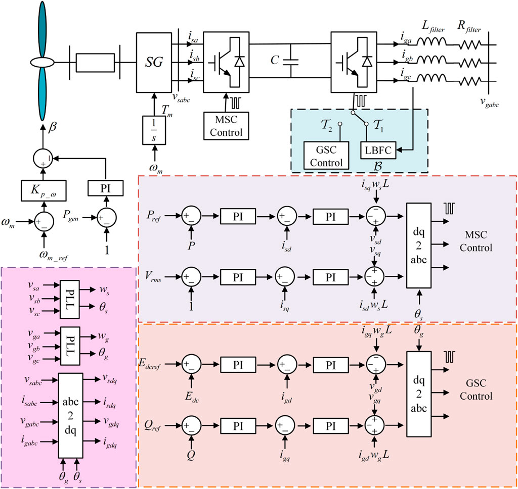
Figure 1. Wind power generation system.
2.1 Model of wind turbine
A wind turbine consists of several components capable of converting kinetic energy into electrical energy. The blades on the wind turbine can convert wind energy into mechanical energy, which is then transmitted through the drive system to the generator, where it is further transformed into electrical energy. Therefore, the wind turbine is a primary and critical component of a WPG system, directly impacting the efficiency of wind power generation.
According to aerodynamic principles, it is possible to express the airflow power as Equation 1.
where
The blades capture wind power can be expressed as Equation 2.
where
When the blade rotates, the ratio of the tip speed to the input wind speed is defined as the tip speed ratio
where
For variable pitch wind turbine,
where
Through computing
2.2 Modelling of PMSG equivalent model
PMSG uses permanent magnet material to replace the excitation winding, and the permanent magnet generates rotor excitation, which is a brushless motor. Since there is no rotor winding, its size and weight are greatly reduced, and there is no rotor winding loss.
Figure 2 shows the equivalent model of PMSG. The time domain model of PMSG in the stationary coordinate system can be represented by voltage equation, flux equation and rotor motion equation. The three-phase stator winding voltage equation can be described as Equation 7.
where
where

Figure 2. Schematic of a PMSG.
According to the theory of permanent magnet motor, the motor motion equation can be written as Equation 10.
where
In the static coordinate system, the uneven air gap leads to the asymmetry of the fixed rotor magnetic field structure, and the projection of the rotor flux on the three-phase stator winding is related to the rotor position Angle. The mathematical model of the synchronous motor is a set of nonlinear time-varying equations related to the instantaneous position of the rotor, which is difficult to analyze and control. After Park transformation, the stator winding is equivalent to the d and q axis winding and the rotor winding are relatively stationary, so that the inductance parameters of the d and q axes become fixed, and the stator voltage, current and flux vector are all constant direct flow that is relatively stationary with the rotor. In PSCAD, the modeling of WPG system can be realized by applying coordinate transformation.
3 Fault current limiting control
3.1 Logical-based bang-bang funnel control (LBFC) design
The three-phase full-bridge inverter’s topology is described in Figure 3, and all of the symbols utilized in the subsequent LBFC design process are defined in Table 1.
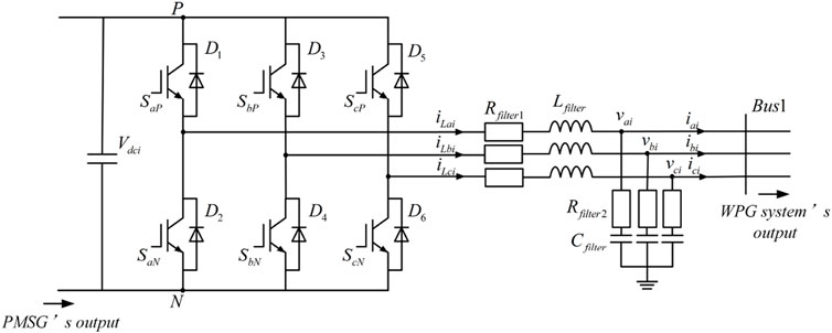
Figure 3. Topology of the three-phase full-bridge inverter.
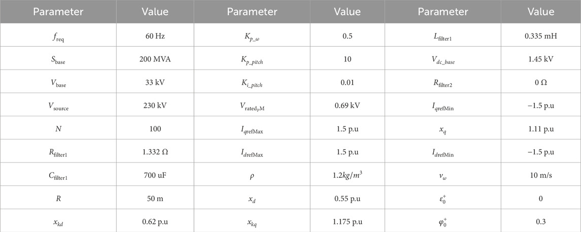
Table 1. Parameters of WPG system.
Obviously, the states of
where
where
where
The order of the LBFC varies depending on the relative degree
when
Therefore, it has
where
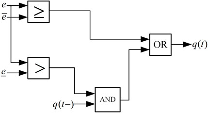
Figure 4. The scheme of LBFC.
On the basis of
3.2 Switching strategy design
The state-dependent strategy

Figure 5. The description of the switching logic.
Assume that following a short-circuit malfunction at the system, the absolute value of any
4 Simulation verifications
PMSG power system is a part of WPG system. In order to verify the effectiveness of fault current rejection through LBFC, time domain simulations of the system considering electromagnetic transients were performed in PSCAD. In the test system, the simulation time is set to 3 s, three-phase current faults happened in 1.5 s on bus 1 and bus 2 separately, and faults were cleared after 90 ms, the type 4 wind turbine model is shown in Figure 6. At the WPG system outlet A, a multimeter is used to measure the voltage, current, active power and reactive power of the turbine output. The voltage and current are measured by unit value, and the active power and reactive power are measured by named value. The result when the system runs stably is displayed in Figure 7.

Figure 6. Structure of the type 4 wind turbine model.

Figure 7. Dynamics of WPG system in steady operation.
4.1 A three-phase current fault occurred on bus 1 of the WPG system at 1.5 s
On bus 1 at
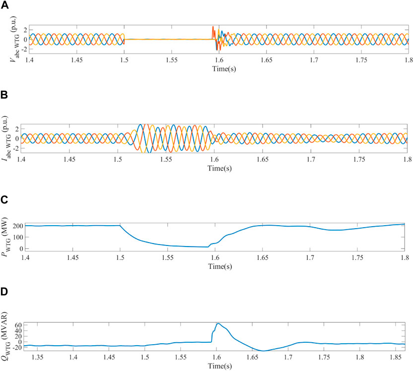
Figure 8. Dynamics of WPG system obtained in the case when three-phase current fault happened on bus 1 under vector control. (A) Three-phase voltages measured on bus 1. (B) Three-phase currents measured on bus 1. (C) Active power output of WPG system. (D) Reactive power output of WPG system on bus 1.
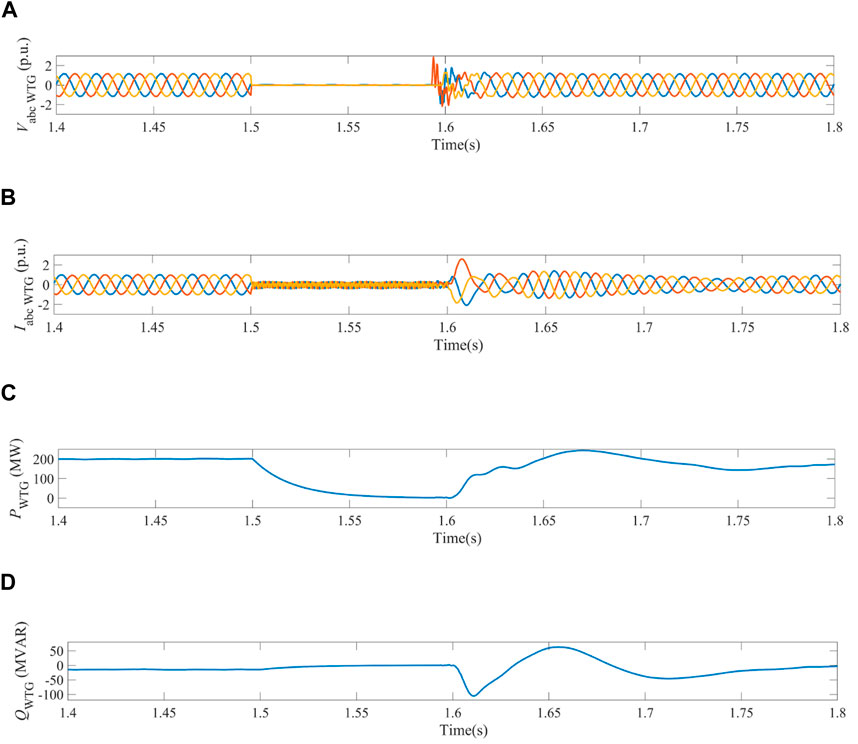
Figure 9. Dynamics of WPG system obtained in the case when three-phase current fault happened on bus 1 under the switching control of vector control and BBFC. (A) Three-phase voltages measured on bus 1. (B) Three-phase currents measured on bus 1. (C) Active power output of WPG system. (D) Reactive power output of WPG system on bus 1.
In contrast, the switching control of vector control and LBFC had an optimizing effect on WPG system during fault time. When the short-circuit current was up to the switching criterion
4.2 A three-phase current fault occurred on bus 2 of the WPG system at 1.5 s
Similarly, three-phase-to-ground fault occurred on bus 2 at
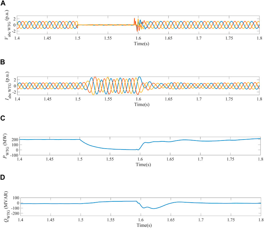
Figure 10. Dynamics of WPG system obtained in the case when three-phase current fault happened on bus 2 under the switching control of vector control. (A) Three-phase voltages measured on bus 1. (B) Three-phase currents measured on bus 1. (C) Active power output of WPG system. (D) Reactive power output of WPG system on bus 1.
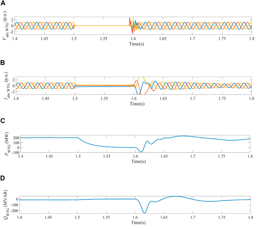
Figure 11. Dynamics of WPG system obtained in the case when three-phase current fault happened on bus 2 under the switching control of vector control and LBFC. (A) Three-phase voltages measured on bus 1. (B) Three-phase currents measured on bus 1. (C) Active power output of WPG system. (D) Reactive power output of WPG system on bus 1.
5 Conclusion
This paper has proposed a FCLS for the full-scale wind power generators based on LBFC. The GSC is controlled in a switched manner with the LBFC and a vector controller. When fault currents are detected, the control system of GSC switches from vector controller to LBFC, which generates independent control signals for the three-phase bridge arms.
Simulation results, obtained in the case when bus 1 and bus 2 happen three-phase-to-ground current fault on the test system, have verified that switching control in conjuction with the LBFC could enhance the dynamics of system during fault and restrain the fault current effectively. LBFC’s fault current rejection avoided prolonged overcurrent, reduced the pressure on the power grid under the fault. In contrast to the original Type 4 wind turbine model in PSCAD, the switching control in conjuction with the LBFC could maintain the three-phase fault current at a low value, about 0.5 times the rated value, where 3 times the rated value without LBFC. Meanwhile, considering the simple structure and excellent ability of limiting fault current, LBFC could be applied into the area of PV system, electrochemical energy storage system and flywheel energy storage system, which helps to reduce the harm of overcurrent to the system. With the switching from LBFC to vector control after fault disappeared, the WPG system would experience an oscillation, leading to the fluctuation of voltage and current in a short time, which is also the inspiration for the future study considering the harmonic stability of the co-ordinated control of vector control and LBFC.
In terms of the difficulties of practical application, the communication delays will put forward potential challenges for the implementation of the LBFC. The sensor accuracy can also impact the performance of the LBFC, and the error of current measurement weakens the effectiveness of the controller.
Data availability statement
The raw data supporting the conclusions of this article will be made available by the authors, without undue reservation.
Author contributions
KS: Methodology, Writing–original draft. JL: Software, Writing–original draft. YZ: Validation, Writing–original draft. HL: Writing–original draft. YL: Writing–review and editing.
Funding
The author(s) declare that no financial support was received for the research, authorship, and/or publication of this article.
Conflict of interest
Authors KS, JL, and YZ were employed by Power China Huadong Engineering Corporation Limited.
The remaining authors declare that the research was conducted in the absence of any commercial or financial relationships that could be construed as a potential conflict of interest.
Publisher’s note
All claims expressed in this article are solely those of the authors and do not necessarily represent those of their affiliated organizations, or those of the publisher, the editors and the reviewers. Any product that may be evaluated in this article, or claim that may be made by its manufacturer, is not guaranteed or endorsed by the publisher.
References
Behera, M. K., and Saikia, L. C. (2022). An improved voltage and frequency control for islanded microgrid using bpf based droop control and optimal third harmonic injection pwm scheme. IEEE Trans. Industry Appl. 58, 2483–2496. doi:10.1109/TIA.2021.3135253
Chandorkar, M., Divan, D., and Adapa, R. (1993). Control of parallel connected inverters in standalone ac supply systems. IEEE Trans. Industry Appl. 29, 136–143. doi:10.1109/28.195899
Chen, L., Wen, T., Lin, Y., Liu, Y., Qin, Y., and Wu, Q.-H. (2024a). Two-stage expanding boundary algorithm to estimate domains of attraction of large-scale power systems with induction motors. IEEE Trans. Power Syst., 1–13. doi:10.1109/TPWRS.2024.3413078
Chen, X., Liu, Y., Wu, Q. H., Hong, C., and Su, Y. (2024b). Direct power regulation of grid-connected voltage-source inverters based on bang-bang funnel control. IEEE Trans. Industrial Electron. 71, 6460–6470. doi:10.1109/TIE.2023.3306418
Chen, X., Wang, L., Liu, Y., and Wu, Q. (2023). Bang-bang funnel control of three-phase full-bridge inverter under dual-buck scheme. IEEE Trans. Industrial Electron. 70, 5399–5409. doi:10.1109/TIE.2022.3198247
Enslin, J. H. (2016). Power system infrastructure: do we face a complete power-electronics-based power system and energy-storage infrastructure? IEEE Power Electron. Mag. 3, 42–45. doi:10.1109/MPEL.2016.2551798
Guerrero, J., de Vicuna, L., Matas, J., Castilla, M., and Miret, J. (2004). A wireless controller to enhance dynamic performance of parallel inverters in distributed generation systems. IEEE Trans. Power Electron. 19, 1205–1213. doi:10.1109/TPEL.2004.833451
Jabr, H. M., Lu, D., and Kar, N. C. (2011). Design and implementation of neuro-fuzzy vector control for wind-driven doubly-fed induction generator. IEEE Trans. Sustain. Energy 2, 404–413. doi:10.1109/TSTE.2011.2160374
Kang, H., Liu, Y., Wu, Q. H., and Zhou, X. (2015). Switching excitation controller for enhancement of transient stability of multi-machine power systems. CSEE J. Power Energy Syst. 1, 86–93. doi:10.17775/CSEEJPES.2015.00039
Kobayashi, H., and Ichiyanagi, K. (1978). Improvement of the transient stability by optimal switching control of parallel ac-dc power systems. IEEE Trans. Power Apparatus Syst. PAS-97, 1140–1148. doi:10.1109/TPAS.1978.354594
Li, J., Chen, J., Wang, Y., and Chen, W. (2024a). Combining multi-step reconfiguration with many-objective reduction as iterative bi-level scheduling for stochastic distribution network. Energy 290, 130198. doi:10.1016/j.energy.2023.130198
Li, Y., Ding, Y., He, S., Hu, F., Duan, J., Wen, G., et al. (2024b). Artificial intelligence-based methods for renewable power system operation. Nat. Rev. Electr. Eng. 1, 163–179. doi:10.1038/s44287-024-00018-9
Li, Y., Fan, L., and Miao, Z. (2020). Wind in weak grids: low-frequency oscillations, subsynchronous oscillations, and torsional interactions. IEEE Trans. Power Syst. 35, 109–118. doi:10.1109/TPWRS.2019.2924412
Li, Y., Yu, C., Shahidehpour, M., Yang, T., Zeng, Z., and Chai, T. (2023). Deep reinforcement learning for smart grid operations: algorithms, applications, and prospects. Proc. IEEE 111, 1055–1096. doi:10.1109/JPROC.2023.3303358
Li, Z., Chan, K. W., Hu, J., and Guerrero, J. M. (2021). Adaptive droop control using adaptive virtual impedance for microgrids with variable pv outputs and load demands. IEEE Trans. Industrial Electron. 68, 9630–9640. doi:10.1109/TIE.2020.3022524
Liberzon, D., and Trenn, S. (2013). The bang-bang funnel controller for uncertain nonlinear systems with arbitrary relative degree. IEEE Trans. Automatic Control 58, 3126–3141. doi:10.1109/TAC.2013.2277631
Liu, J., Chen, J., Yan, G., Chen, W., and Xu, B. (2023a). Clustering and dynamic recognition based auto-reservoir neural network: a wait-and-see approach for short-term park power load forecasting. iScience 26, 107456. doi:10.1016/j.isci.2023.107456
Liu, X., and Kong, X. (2014). Nonlinear model predictive control for dfig-based wind power generation. IEEE Trans. Automation Sci. Eng. 11, 1046–1055. doi:10.1109/TASE.2013.2284066
Liu, Y., Jiang, L., Wu, Q. H., and Zhou, X. (2017). Frequency control of dfig-based wind power penetrated power systems using switching angle controller and agc. IEEE Trans. Power Syst. 32, 1553–1567. doi:10.1109/TPWRS.2016.2587938
Liu, Y., Lin, Z., Xu, C., and Wang, L. (2023b). Fault ride-through hybrid controller for mmc-hvdc transmission system via switching control units based on bang-bang funnel controller. J. Mod. Power Syst. Clean Energy 11, 599–610. doi:10.35833/MPCE.2021.000470
Liu, Y., Wu, Q. H., and Zhou, X. X. (2016a). Co-ordinated multiloop switching control of dfig for resilience enhancement of wind power penetrated power systems. IEEE Trans. Sustain. Energy 7, 1089–1099. doi:10.1109/TSTE.2016.2524683
Liu, Y., Wu, Q. H., and Zhou, X. X. (2016b). Coordinated switching controllers for transient stability of multi-machine power systems. IEEE Trans. Power Syst. 31, 3937–3949. doi:10.1109/TPWRS.2015.2495159
Liu, Y., Yao, H., Chen, Z., Pei, X., Yang, Y., and Wu, Q. H. (2024). Estimating the region of attraction of wind integrated power systems based on improved expanding interior algorithm. IET Generation, Transm. & Distribution 18, 2242–2257. doi:10.1049/gtd2.13201
Martinez, M. I., Tapia, G., Susperregui, A., and Camblong, H. (2012). Sliding-mode control for dfig rotor- and grid-side converters under unbalanced and harmonically distorted grid voltage. IEEE Trans. Energy Convers. 27, 328–339. doi:10.1109/TEC.2011.2181996
Marwali, M., Jung, J.-W., and Keyhani, A. (2004). Control of distributed generation systems - part ii: load sharing control. IEEE Trans. Power Electron. 19, 1551–1561. doi:10.1109/TPEL.2004.836634
Marwali, M. N., Jung, J.-W., and Keyhani, A. (2007). Stability analysis of load sharing control for distributed generation systems. IEEE Trans. Energy Convers. 22, 737–745. doi:10.1109/TEC.2006.881397
Silva, G. F., Donaire, A., Seron, M. M., McFadyen, A., and Ford, J. (2022). String stability in microgrids using frequency controlled inverter chains. IEEE Control Syst. Lett. 6, 1484–1489. doi:10.1109/LCSYS.2021.3114143
Wang, Y., Chen, J., Zhao, Y., and Xu, B. (2024). Incorporate robust optimization and demand defense for optimal planning of shared rental energy storage in multi-user industrial park. Energy 301, 131721. doi:10.1016/j.energy.2024.131721
Wang, Y., Meng, J., Zhang, X., and Xu, L. (2015). Control of pmsg-based wind turbines for system inertial response and power oscillation damping. IEEE Trans. Sustain. Energy 6, 565–574. doi:10.1109/TSTE.2015.2394363
Keywords: bang-bang funnel controller, fault current limiting, switching control, wind turbine generator, wind turbine
Citation: Shen K, Li J, Zhang Y, Li H and Liu Y (2024) Fault current limiting control of full-scale wind power generators based on switched bang-bang scheme. Front. Energy Res. 12:1472378. doi: 10.3389/fenrg.2024.1472378
Received: 29 July 2024; Accepted: 09 September 2024;
Published: 20 September 2024.
Edited by:
Zhenjia Lin, Hong Kong Polytechnic University, Hong Kong SAR, ChinaReviewed by:
Yiyan Sang, Shanghai University of Electric Power, ChinaJ. J. Chen, Shandong University of Technology, China
Muhammad Faizan Tahir, South China University of Technology, China
Copyright © 2024 Shen, Li, Zhang, Li and Liu. This is an open-access article distributed under the terms of the Creative Commons Attribution License (CC BY). The use, distribution or reproduction in other forums is permitted, provided the original author(s) and the copyright owner(s) are credited and that the original publication in this journal is cited, in accordance with accepted academic practice. No use, distribution or reproduction is permitted which does not comply with these terms.
*Correspondence: Haoheng Li, ZXBob2VuQG1haWwuc2N1dC5lZHUuY24=