 Wenju Sang1,2
 Wenyong Guo3*Gang Xu4*Tongzhen Wei1,2*Changli Shi1,2Zongjie Liu5Han Xue5Zhenning He4Junzhi Li6Jiazhen Shen3Ruiqi Min3Shaobo Song3Xiaoxu Li3Yun Hong3
- 1Institute of Electrical Engineering, Chinese Academy of Sciences, Beijing, China
- 2University of Chinese Academy of Sciences, Beijing, China
- 3School of Electrical Engineering, Bejing Jiaotong University, Beijing, China
- 4Shanghai Institute of Satellite Engineering, Shanghai, China
- 5State Grid Shandong Electric Power Company, Jinan, China
- 6R&D Department at Hiconics Eco-energy Technology Co., Ltd., Beijing, China
LCL-type grid-connected inverters have been widely used in renewable power generation due to their size and cost advantages. However, the LCL filter has a problem of insufficient damping, which may lead to power system instability. Two common methods are used to address this problem: passive damping (PD) and active damping (AD). PD methods suppress resonance by adding resistors to the LCL filter, but this approach increases system losses. AD methods enhance damping through control to suppress resonance. Existing AD methods are often significantly affected by grid-side inductance perturbation, resulting in insufficient robustness. To address this issue, this article proposes a novel robust active damping (RAD) control strategy based on H∞ loop shaping. Simulation analysis and experimental research show that the RAD control method exhibits superior robustness compared with the traditional capacitor current active damping control.
1 Introduction
Grid-connected inverters serve as critical interfaces between distributed energy resources and the power grid, playing an essential role in enhancing system efficiency, power quality, and reliability (Jinming et al., 2016). To meet grid connection standards, the output current of inverters must be filtered to reduce total harmonic distortion (THD). Typically, grid-connected inverter filters include L and LCL types. While the L filter is simple in design, its high-frequency harmonic attenuation performance is weak. Achieving effective harmonic suppression with L filters necessitates either larger inductance values or higher switching frequencies (Sosa et al., 2014). In contrast, LCL filters offer superior high-frequency harmonic suppression, along with advantages in terms of reduced size and cost, thus garnering widespread application (Wu et al., 2023). Nevertheless, LCL filters are prone to resonance issues that can destabilize grid-side current control (Chen et al., 2022). Researchers have proposed multiple solutions to mitigate the resonance problems associated with direct grid-side current control.
The traditional capacitor current active damping (CCAD) approach is widely used due to its simple implementation. The inner loop of the capacitor current is used to achieve active damping to suppress LCL resonance, and the outer loop of the grid-connected current directly controls the grid current through the proportional-integral (PI) controller (Zhi-ying et al., 2009; He et al., 2019; Pan et al., 2013). However, the large ripple in the filter capacitor current weakens the active damping (AD) effect. Additional current sensors are required, increasing the control cost (NIU et al., 2023; Xin et al., 2017). Chen et al. (2022) proposed a design method for optimal damping ratio based on CCAD. However, the impact of sampling and computational time delays on the AD ratio is not compensated. Wang et al. (2023) proposed a method of AD implementation based on capacitor voltage differential feedback. This method replaces the capacitor current with the differential of the capacitor voltage, which can suppress LCL resonance without the need for extra current sensors, thus reducing system cost. However, the differential operation will amplify measure noise, which reduces the damping effect and in turn, affects the grid-connect current quality. Ma et al. (2021) and Zhao et al. (2022) proposed full-dimensional/reduced-dimensional state observers to estimate the capacitor current, but this estimation method relies on an accurate system model and can also affect the dynamic behavior of the system. Dragievic et al. (2019) proposed a predictive current control model that has the advantages of good dynamic performance and easy implementation, but this algorithm relies on accurate parameters of the grid-side equivalent inductance. In the case of grid-side inductance perturbation, an indirect grid-side current control method is proposed by Marcos et al. (2018) and Zhou and Lu (2002), which indirectly controls the grid-connected current by controlling the inverter-side current. This method avoids the resonance problem brought by direct control of the grid-connected current. However, resonance may occur between the grid-side inductance and the filter capacitor due to a perturbation in the grid-side inductance, leading to distortion in the grid-connected current.
In summary, parametric uncertainties due to the aging of LCL filter components, magnetic core saturation, or perturbations in grid-side inductance can degrade the performance of AD that is designed based on the above classical control theory, resulting in inadequate robustness.
H∞ control offers advantages for models with parameter uncertainty. Recently, the H∞ robust control method has been applied to implement AD. A standard H∞ mixed sensitivity robust control method is proposed to regulate the output voltage of the nominal system under input voltage fluctuations cases (Wu et al., 2021). Gholami-Khesht (2021) designed the H∞ controller assigned to integrators from an optimal solution of a convex optimization problem subject to some LMI conditions. Chen and Ye (2024) explored the influence of AD filters on the LCL filter’s resonant peak and proposed a robust H∞ AD filter with a preserved resonant peak. However, the above AD filters based on the H∞ control method were implemented by sensitivity weighting functions, input weighting functions, and output weighting functions. The selection of weighting functions can be troublesome and requires repeated attempts.
The H∞ control method focuses on minimizing the transfer function from external inputs to evaluation signals under the worst disturbance. The AD is obtained during the process. The AD design lacks intuitiveness and relies on design experience. Unlike traditional H∞ control, the design process of H∞ loop-shaping control is straightforward and simplified. It has the following characteristics: (1) the algorithm implementation is simple, and no iteration is required. (2) The robust stability margin can be calculated precisely. (3) The H∞ norm is not a performance index but rather a stability margin. H∞ loop-shaping control is used in the control of train systems, spacecraft, and nonlinear hard disk drive (HDD) systems (Cheng et al., 2024; Faure et al., 2022; Shaikh et al., 2024). Few studies have researched the application of H∞ loop-shaping control methods for LCL-type grid-connected inverters. It deserves further research.
To enhance the robustness of AD for grid-connected current control and simplify the complexity of control design, this article proposes a novel robust active damping (RAD) control method based on H∞ loop shaping, which does not require an additional current or voltage feedback loop. It shapes the high-, medium-, and low-frequency characteristics of the open-loop transfer function’s magnitude–frequency curve directly by choosing appropriate weight functions to satisfy specific performance objectives (Liu et al., 2021). This concept of loop shaping is consistent with classical control principles, where control performance is achieved through weight functions. Additionally, robustness is guaranteed by applying the small-gain theorem. The H∞ loop-shaping controller combines weight functions and H∞ control, thus integrating the advantages of both classical loop shaping and H∞ control techniques.
The remainder of this article is organized as follows: Section 2 provides an overview of the modeling and design of an AD controller based on H∞ loop shaping. In Section 3, the RAD realization method is presented. In Section 4, a robustness analysis and comparison is conducted between the RAD and CCAD. In Section 5, an experimental comparative analysis is presented between the CCAD and RAD control strategies. Finally, conclusions are drawn in Section 6.
2 Modeling and design of an AD controller based on H∞ loop shaping
2.1 The mathematical model of the grid-connected inverter
A typical LCL-type inverter grid-connected topology is shown in Figure 1. It consists of a three-phase bridge inverter, an inverter-side inductor L1, a filter capacitor C, a grid-side inductor L2, and a grid inductor Lg. Udc is the DC bus voltage, and Cdc is the DC bus capacitor. The grid-connected current control block diagram shown in Figure 2 is based on the circuit topology shown in Figure 1.
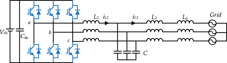
Figure 1. Topology of the LCL-type grid-connected VSI.
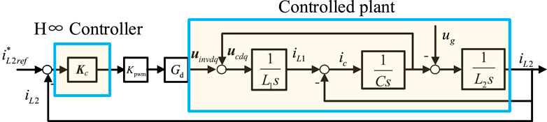
Figure 2. Control block diagrams of the LCL-type grid-connected VSI.
According to Figure 2, the transfer function from inverter voltage to grid-connected current is as follows:
where
The computation and pulse width modulated (PWM) delay can be approximated to one and a half of the sampling periods. Consequently, the total time delay can be expressed as
2.2 Active damping design
As illustrated in Figure 3, passive damping (PD) can be realized through various configurations of resistors, including series resistors with grid-side inductance, parallel resistors with grid-side inductance, series resistors with capacitor branch, parallel resistors with capacitor branch, series resistors with inverter-side inductance, and parallel resistors with inverter-side inductance. Among these configurations, the PD achieved by paralleling a resistor with a capacitor is particularly effective in suppressing resonance peaks in the mid-frequency band while maintaining the original frequency characteristics in both low- and high-frequency bands. Utilizing this PD approach, the

Figure 3. Various implementation methods of PD for the LCL-type grid-connected VSI.
The control block diagram for AD with capacitor current, capacitor voltage, and grid-side current feedback is illustrated in Figure 4. The

Figure 4. Active damping control block diagram with capacitor current feedback, capacitor voltage feedback, and grid-side current feedback.

Table 1. Active damping and passive damping grid-connected current transfer function.
From Table 1, it is evident that the structure of
H∞ loop-shaping control is composed of the weight function and the controlled plant. The high cutoff frequency is set in the mid-frequency range, the high gain is set in the low-frequency range, and the low gain is set in the high-frequency range. This gives the closed-loop system good dynamic and static characteristics. The original controlled plant
The implementation process of the H∞ loop-shaping method is shown in Figure 5A. The plant
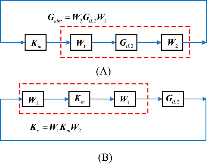
Figure 5. Implementation process of the H∞ loop-shaping method: (A) Construction of the desired transfer function and (B) formation of the H∞ loop-shaping controller.
Based on the implementation process of the H∞ loop-shaping method, this article proposes the following RAD implementation method:
A damping term
From Equation 3, it can be seen that the structure of the desired transfer function is the same as Equation 2, which ensures the proposed RAD has the same damping function as the PD method. The weighting transfer function to achieve the desired transfer function can be derived as
The selection of the aforementioned weighting function is determined based on the desired transfer function, thereby reducing the number of trial-and-error cycles required to select the weighting function. Because
Furthermore, as shown in Figure 5B, the H∞ loop-shaping controller described by Equation 5 is composed of
2.3 Design for improved dynamic and steady-state performance
To ensure the system’s steady-state accuracy and response speed, a PI controller is applied to the damped controlled plant whose transfer function is shown in (5). Then
where Kp is the proportional controller coefficient, and Ki is the integral controller coefficient.
Correspondingly, Equation 6 and
3 The solution to the H∞ loop-shaping controller
First, a normalized coprime factorization of the perturbed plant model
3.1 Coprime factorization
The normalized left coprime factorization of
Here,
Based on Equation 9, the left coprime factorization of
Here,
The standard feedback control system in the form of coprime factorization is shown in Figure 6 based on Equation 10.
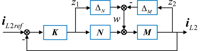
Figure 6. The feedback control block diagram in the form of coprime factorization.
3.2 Deriving the solution for the controller
For the perturbed feedback system of Figure 6, the system stability is robust according to the small-gain theorem, which requires Equation 11 to be satisfied.
where
Because the norms of the normalized coprime factorizations
The minimum value of
where
where (
For the specified
where
From Equation 12, it can be seen that, unlike the classical PI controller, the H∞ loop-shaping controller does not have a specific structure. Its design depends on the shape of the objective function and the stability margin considering system uncertainties, thus offering greater design flexibility.
4 Robustness comparative analysis
Based on Equation 11, it is evident that the designed

Figure 7. Equivalent block diagram of RAD.
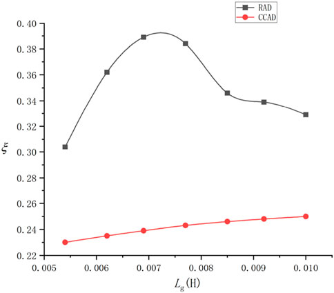
Figure 8. Curve of
Using the experimental parameters shown in Table 2, the damping ratio
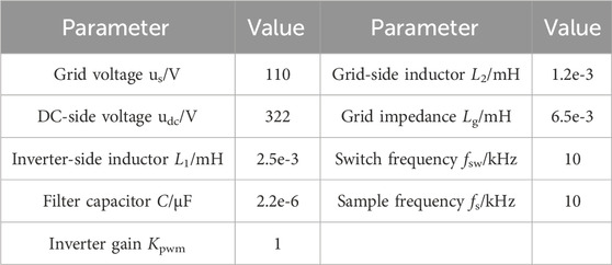
Table 2. Grid-connected inverter system parameters.
As shown in Figure 8, when the values of
5 Experimental verification
An experimental platform was set up to verify the effectiveness of the RAD control method proposed in this article, as shown in Figure 9. The performance of the RAD was compared with that of the CCAD. The steady-state performance, dynamic response, and robustness to inductance change were evaluated. The RTU-BOX201 controllers and the RTI-INV6020IR inverters were both produced by Nanjing Ruitu Youte Technology Co., Ltd., and the grid simulator was the Chroma 61815. The circuit parameters of the experimental system are listed in Table 2.
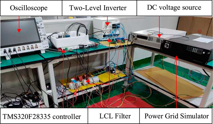
Figure 9. Three-phase LCL grid-connected inverter experimental platform.
For the desired transfer function in Equation 7, with
CCAD control parameter design: according to the CCAD control method proposed by Chen et al. (2023), Kad is set to 55. The bandwidth of the current loop is generally taken as 1/10 of the switching frequency, and the phase margin is set to 45° (Yang et al., 2021). The control parameters listed in Table 3 are obtained.
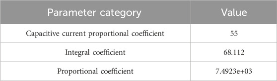
Table 3. CCAD control parameters.
5.1 Steady-state performance analysis
The harmonic levels of grid current for the CCAD and RAD control strategies are illustrated in Figure 10. As depicted in Figure 10A, the total harmonic distortion (THD) of the three-phase grid-side current under the CCAD control strategy is 3.1%. Figure 10B shows that the THD of the three-phase grid-side current with the RAD control strategy is 1.7%. The experimental results demonstrate that the RAD control strategy yields a lower THD in the grid-side current. This improvement is attributed to the higher damping ratio of the proposed method.
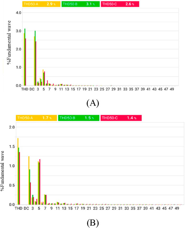
Figure 10. Harmonics of grid-side current under steady-state conditions. (A) CCAD control strategy and (B) RAD control strategy.
5.2 Dynamic characteristic analysis
The dynamic response of the CCAD control strategy is shown in Figure 11A. When the reference active current
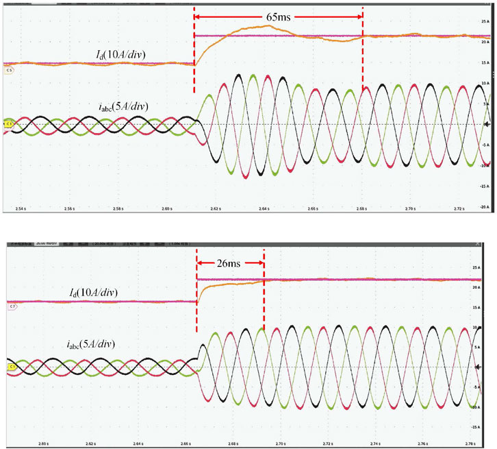
Figure 11. Waveforms of active current and grid-side three-phase current when the active reference current suddenly changes. (A) CCAD control strategy and (B) RAD control strategy.
5.3 Robustness analysis under the perturbation of grid-side inductance parameters
Figure 12 shows the waveforms of active current
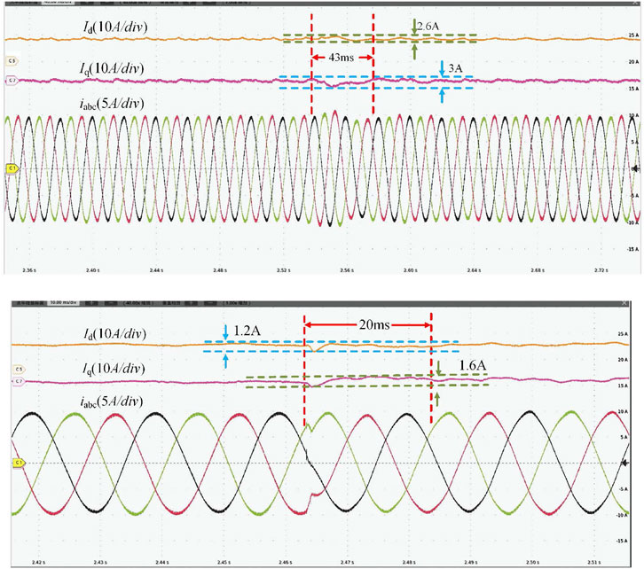
Figure 12. Experimental waveform of the grid-side current
Figure 13 shows the waveforms of the active current
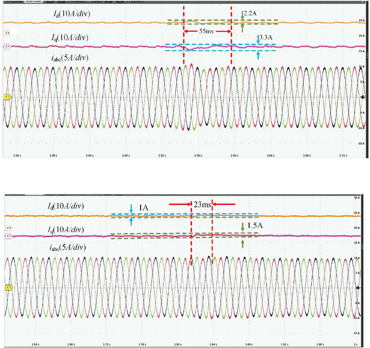
Figure 13. Experimental waveform of the grid-side current
Due to the constraints of experimental conditions, the root locus method is used to determine the allowable range of variation for Lg. The range of variation for Lg is from 0.003 to 0.5, as shown in Figure 14.
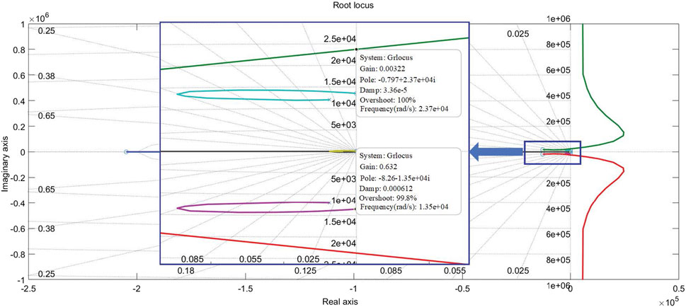
Figure 14. The root locus of the system when Lg varies.
Table 4 lists the THD of the grid-side current with RAD and CCAD. The data presented in Table 4 indicate that the grid-side current THD with the RAD control strategy consistently remains lower than that with the CCAD control strategy.

Table 4. The total harmonic distortion (THD) of the grid-side current under grid-side inductance perturbation.
Under the aforementioned operating conditions, the RAD control strategy exhibits superior robustness and lower THD. This enhanced performance is attributed to the higher damping ratio achieved by the proposed control method compared to the CCAD approach under varying grid-side inductance conditions. The robustness and disturbance rejection capabilities of the proposed method enable the system to maintain more stable performance amid external disturbances induced by grid-side inductance variation.
6 Conclusion
This study presents a novel RAD control strategy based on H∞ loop-shaping technology to address the robustness insufficiency of the conventional AD control methods. This control strategy avoids introducing a new feedback control loop with additional sensors or state observers via H∞ loop-shaping technology, reducing costs and enhancing robustness. Through extensive analysis and experimental comparison, it is found that the RAD control exhibits a high active damping ratio compared with that of the CCAD under various grid-side inductances, demonstrating better dynamic and static performance.
Data availability statement
The original contributions presented in the study are included in the article/Supplementary Material; further inquiries can be directed to the corresponding author.
Author contributions
WS: formal analysis, investigation, methodology, software, and writing–original draft. WG: methodology and writing–review and editing. GX: conceptualization, data curation, and writing–review and editing. TW: conceptualization, data curation, and writing–review and editing. CS: validation and writing–review and editing. ZL: resources and writing–review and editing. HX: resources and writing–review and editing. ZH: data curation and writing–review and editing. JL: resources and writing–review and editing. JS: resources and writing–review and editing. RM: writing–review and editing. SS: writing–review and editing. XL: writing–review and editing. YH: writing–review and editing.
Funding
The author(s) declare that financial support was received for the research, authorship, and/or publication of this article. This work was supported by the Fundamental Research Funds for the Central Universities (Grant No. 2022XKRC018) and the National Key R&D Program of China (Grant Nos. 2022YFB2402900 and 52060023001T).
Conflict of interest
Authors ZL and HX were employed by the State Grid Shandong Electric Power Company. Author JL was employed by the R&D Department at Hiconics Eco-energy Technology Co.
The remaining authors declare that the research was conducted in the absence of any commercial or financial relationships that could be construed as a potential conflict of interest.
Publisher’s note
All claims expressed in this article are solely those of the authors and do not necessarily represent those of their affiliated organizations, or those of the publisher, the editors, and the reviewers. Any product that may be evaluated in this article, or claim that may be made by its manufacturer, is not guaranteed or endorsed by the publisher.
References
Chen, S., and Ye, Y. (2024). Robust H∞ active damping filter with preserved resonant peak for resonant harmonic suppression. IEEE J. Emerg. Sel. Top. POWER Electron. 12 (3), 2580–2591. doi:10.1109/JESTPE.2024.3375302
Chen, W., Zhang, Y., Tu, Y., Guan, Y., Shen, K., and Liu, J. (2023). Unified active damping strategy based on generalized virtual impedance in LCL-type grid-connected inverter. IEEE Trans. Industrial Electron. 70 (8), 8129–8139. doi:10.1109/TIE.2022.3232647
Chen, W., Zhang, Y., Tu, Y., Shen, Ke, and Liu, J. (2022). Active damping control for LCL filters with inverter-side current feedback only. IEEE Trans. Power Electron. 37 (9), 10065–10069. doi:10.1109/TPEL.2022.3159229
Cheng, S., Ma, L., Liu, F., Ge, X., and Zhou, K. (2024). Low-frequency oscillation suppression of train–grid coupling systems by H∞ loop shaping. IEEE Trans. Transp. Electrification 10 (2), 4470–4483. doi:10.1109/TTE.2023.3314007
Dragievic, T., Zheng, C., Rodriguez, J., and Blaabjerg, F. (2019). Robust quasi-predictive control of $LCL$-Filtered grid converters. IEEE Trans. Power Electron. 35 (2), 1934–1946. doi:10.1109/TPEL.2019.2916604
Faure, M., Henry, D., and Cieslak, J. (2022). A H∞ control solution for space debris removal missions using robotic arms: the ESA e.Deorbit case. 2022 UKACC 13th International Conference on Control (CONTROL), Plymouth, United Kingdom. doi:10.1109/Control55989.2022.9781461
Gholami-Khesht, H. (2021). “Robust H∞ current control of three-phase grid connected voltage source converters using linear matrix inequalities,” in 2021 IEEE 22nd workshop on control and modelling of power electronics. Cartagena, Colombia. doi:10.1109/COMPEL52922.2021.9646071
He, Y., Wang, X., Ruan, X., Pan, D., Xu, X., and Liu, F. (2019). Capacitor-current proportional-integral positive feedback active damping for LCL-type grid-connected inverter to achieve high robustness against grid impedance variation. IEEE Trans. Power Electron. 34 (15), 12423–12436. doi:10.1109/TPEL.2019.2906217
He, Z., Fan-Wei, MENG, Liu, , and Wang, G. (2010). Synthesis in H-infinity loop-shaping design. ACTA AUTOM. SIN 36 (6), 347–352. doi:10.3724/sp.j.1004.2010.00347
Jinming, X. U., Lin, J. I., Xiaowei, G. E., and Shaojun, X. I. E. (2016). LCL-Filter optimization design with consideration of inverter-side current feedback control impacts. Proc. CSEE 36 (17), 4656–4665. doi:10.13334/j.0258-8013.pcsee.151579
Lanzon, A., and Tsiotras, P. (2005). A combined application of H/sub/spl infin//loop shaping and/spl mu/-synthesis to control high-speed flywheels. IEEE Trans. Control Syst. Technol. 13 (5), 766–777. doi:10.1109/TCST.2005.847344
Liu, H., Lei, M. A., and Lin, PENG (2021). H∞ loop-shaping robust direct current control for single-phase PWM rectifier. Power Syst. Technol. 45 (4), 1429–1437. doi:10.13335/j.1000-3673.pst.2020.0637
Ma, A., Flora, L. D., and Husain, I. (2021). Observer based generalized active damping for voltage source converters with LCL filters. IEEE Trans. Power Electron. 37 (1), 125–136. doi:10.1109/TPEL.2021.3093504
Marcos, G. J., González, S. A., Fischer, J. R., Martinez, J. F., and Carrica, D. O. (2018). Inverter-side current control of grid-connected voltage source inverters with LCL filter based on generalized predictive control. IEEE J. Emerg. Sel. Top. Power Electron. 6 (4), 1732–1743. doi:10.1109/JESTPE.2018.2826365
Niu, C., Xiao, H., Li, M., Cao, Q., Yao, Z., Xiao, H., et al. (2023). Method of achieving active damping by filter capacitor voltage feedback with equivalent differential link. Electr. Power Autom. Equip. 43 (6), 204–210. doi:10.16081/j.epae.202211017
Pan, D., Ruan, X., Bao, C., Li, W., and Wang, X. (2013). Capacitor-currentfeedback active damping with reduced computation delay for improving robustness of LCL-type grid-connected inverter. IEEE Trans. Power Electron. 29 (7), 3414–3427. doi:10.1109/TPEL.2013.2279206
Shaikh, I., Matušů, R., Zerdazi, El W., and Wendimu, A. A. (2024). H∞ loop-shaping continuous-time controller design for nonlinear HDD systems: a reduced-order approach using hankel-norm approximation. IEEE Access 12, 111523–111534. doi:10.1109/access.2024.3441754
Sigurd, S. (2005). Multivariable Feedback Control Analysis and design. 2nd ed., 405–406. American: Hoboken.
Sosa, J. M., Escobar, G., Martínez-Rodríguez, P. R., Vazquez, G., and Diosdado, M. (2014). “Comparative evaluation of L and LCL filters in transformer less grid tied converters for active power injection,” in 2014 IEEE international autumn meeting on power, electronics and computing (ROPEC), ixtapa, Mexico, 1–6.
WANG, A., Ge, W., Li, T., Cui, D., Li, M., and Xiao, H. (2023). Research on realization technology of active damping method with differential feedback of filter capacitance voltage for LCL filter based grid-connected inverters. J. Electr. Eng. 18 (1), 126–132. doi:10.11985/2023.01.014
Wu, TSAI.-F. U., Chan, CHING.-CHIH, Chang, Y. U. N.-HSIANG, Chiu, J. Y., Hung, C. C., and Chuang, T. H. (2023). Grid-side current improvement with direct digital control and capacitor voltage feedforward to mitigate distorted grid currents for 3Φ3W LCL grid-connected inverter under distorted grid voltages. IEEE Open J. Power Electron. 5, 37–49. doi:10.1109/OJPEL.2023.3335220
Wu, X., Xu, C., Wei, B., Xia, C., and Li, X. (2021). H mixed sensitivity robust control method of relay ICPT system for output voltage regulation. Electr. Eng. 103, 781–792. doi:10.1007/s00202-020-01116-1
Xin, Z., Wang, X., Loh, P. C., and Blaabjerg, F. (2017). Grid-current-feedback control for LCL-filtered grid converters with enhanced stability. IEEE Trans. Power Electron. 32 (4), 3216–3228. doi:10.1109/TPEL.2016.2580543
Yang, L. I., Qi, R., and Ming-guang, D. A. I. (2021). Linear active disturbance rejection control with adjustable compensation factor applied for outer voltage control of inverter. J. Zhejiang Univ. Eng. Sci. 55 (7), 1279–1288. doi:10.3785/j.issn.1008-973X.2021.07.007
Zhao, J., Xie, C., Li, K., Zou, J., and Guerrero, J. M. (2022). Passivity-oriented design of LCL-type grid-connected inverters with luenberger observer-based active damping. IEEE Trans. Power Electron. 37 (3), 2625–2635. doi:10.1109/TPEL.2021.3109434
Zhi-ying, X. U., Ai-guo, X. U., and Shao-jun, X. I. E. (2019). Dual-loop grid current control technique for grid-connected inverter using an LCL filter. Proc. CSEE 29 (27), 36–41. doi:10.1109/MILCOM.2009.5379889
Keywords: active damping, robustness, LCL resonance, stability, coprime factorization
Citation: Sang W, Guo W, Xu G, Wei T, Shi C, Liu Z, Xue H, He Z, Li J, Shen J, Min R, Song S, Li X and Hong Y (2024) A novel robust active damping control strategy based on H∞ loop shaping for the grid-tied LCL inverter. Front. Energy Res. 12:1473060. doi: 10.3389/fenrg.2024.1473060
Received: 30 July 2024; Accepted: 18 September 2024;
Published: 18 October 2024.
Edited by:
Roberto Francisco Coelho, Federal University of Santa Catarina, BrazilReviewed by:
Shiqi Jiang, Harbin Institute of Technology, ChinaThiago Fonseca Rech, Federal University of Santa Catarina, Brazil
Copyright © 2024 Sang, Guo, Xu, Wei, Shi, Liu, Xue, He, Li, Shen, Min, Song, Li and Hong. This is an open-access article distributed under the terms of the Creative Commons Attribution License (CC BY). The use, distribution or reproduction in other forums is permitted, provided the original author(s) and the copyright owner(s) are credited and that the original publication in this journal is cited, in accordance with accepted academic practice. No use, distribution or reproduction is permitted which does not comply with these terms.
*Correspondence: Wenyong Guo, d3lndW9AYmp0dS5lZHUuY24=; Gang Xu, YWFyb254dWdAMTI2LmNvbQ==; Tongzhen Wei, dHp3ZWlAbWFpbC5pZWUuYWMuY24=